High efficiency, high power, multi-purpose cap charger
Dédé!, Wed Aug 02 2017, 10:29PMI've designed a simple cap charger that's supposed to be capable of sinking a constant preset current until the caps are full. This is because that way, I can prevent the breaker from tripping, while utilizing the most power I can get.
Here's the link to the schematic file: https://1drv.ms/u/s!AivKI_CNHUurn4xH80XiQieReZuM0Q
And here's an image of the schematic: http://i.imgur.com/U0GTM9w.png
It's basically a buck boost converter. The sink current is regulated with an inductor (L1 through L3) and a mosfet (M2). Capacitor C1 is used to minimize voltage spikes caused by opening M2. When the voltage across this capacitor gets above a certain voltage that's configured using R19 and R20, M2 starts conducting again to dump the excess energy into the Inductors L4 through L6. If the current through these inductors gets too high, Mosfet M2 opens. If the current through the inductor gets too low, M1 closes. When the Capacitor C2 reaches the desired voltage, both M1 and M2 open.
All 5V voltage sources you see in the schematic will just use a simple transformer and linear voltage regulator, though I haven't actually decided on whether to use 3.3V or 5V. The mosfet drivers will be powered by a +/-12V supply.
I was wondering if there's any fatal flaw in my design that I might have missed. Do you have any ideas to make this design simpler or better?
I haven't selected any components yet, except for the inductors: http://www.mouser.com/ds/2/445/744839010400-1089993.pdf
However, I think using these chokes in this configuration might saturate the core? Or maybe there's another problem when doing this? What do you think?
I will appreciate any feedback I get!
-Dehim
Re: High efficiency, high power, multi-purpose cap charger
DerAlbi, Wed Aug 02 2017, 11:26PM
Hi,
i have some trouble clicking on your links, but copy&paste works fine. Possible wrong use of the Link-Tag?
Anyways, you want feedback ^_^ I havent played around with it that much, but at least in my simulation the circuit seems impactical or not behaving "nice".
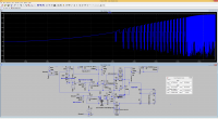
See the image:

This is the drain-current of M2 and in my simulation its (hard-)switching the current (30A and up) with 1.8MHz and more. If you can verify that issue in your circuit, please take note that hard switching is the most brutal thing you can do to a Mosfet and this leas to extreme losses.
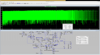
By holding down ALT and clicking the mouse with the thermometer-symbol on a device you can see a devices power dissipation. Then zoom in to an interesting area and hold CTRL and click on the waveform name the text above the waveform, green in the picture below) This will give you integrals and interesting data.

As you can see you are dissipating 650W. This means instant death to the Mosfet.
With those tools, please check all active devices for those restriction. An average power in a TO220 case should be less than 30W..
However you simulation parameter states a simulation time of 0.5 seconds. If this is true, my simulation is fucked up somehow and i take back everything. If you never simulated 0.5 seconds, please reduce the simulation time to the actual time you want to simulate or the usual time where you kill the simulation. LTSpice scales its default time steps according to the overall time and this is why you needed the 1us max. timestep. If you set your time to 10ms, then this might become unnecessary and you can let spice decide the fasted simulation timestep on its own without sacrificing precision.
DerAlbi, Wed Aug 02 2017, 11:26PM
Hi,
i have some trouble clicking on your links, but copy&paste works fine. Possible wrong use of the Link-Tag?
Anyways, you want feedback ^_^ I havent played around with it that much, but at least in my simulation the circuit seems impactical or not behaving "nice".
See the image:

This is the drain-current of M2 and in my simulation its (hard-)switching the current (30A and up) with 1.8MHz and more. If you can verify that issue in your circuit, please take note that hard switching is the most brutal thing you can do to a Mosfet and this leas to extreme losses.
By holding down ALT and clicking the mouse with the thermometer-symbol on a device you can see a devices power dissipation. Then zoom in to an interesting area and hold CTRL and click on the waveform name the text above the waveform, green in the picture below) This will give you integrals and interesting data.

As you can see you are dissipating 650W. This means instant death to the Mosfet.
With those tools, please check all active devices for those restriction. An average power in a TO220 case should be less than 30W..
However you simulation parameter states a simulation time of 0.5 seconds. If this is true, my simulation is fucked up somehow and i take back everything. If you never simulated 0.5 seconds, please reduce the simulation time to the actual time you want to simulate or the usual time where you kill the simulation. LTSpice scales its default time steps according to the overall time and this is why you needed the 1us max. timestep. If you set your time to 10ms, then this might become unnecessary and you can let spice decide the fasted simulation timestep on its own without sacrificing precision.
Re: High efficiency, high power, multi-purpose cap charger
2Spoons, Wed Aug 02 2017, 11:33PM
I think you need to pick a different inductor. The one you've linked to is designed for EMC suppression.
2Spoons, Wed Aug 02 2017, 11:33PM
I think you need to pick a different inductor. The one you've linked to is designed for EMC suppression.
Re: High efficiency, high power, multi-purpose cap charger
Dédé!, Thu Aug 03 2017, 01:04PM
Thanks for your feedback, DerAlbi! I highly appreciate it.
It's been a while since I've posted on 4hv or any forum for that matter, so yea I misused the link-tag.
I never thought hard-switching would be that much of a problem with a buck/boost-converter, since, until now I've only seen hard switching buck/boost-converter topologies and just supposed that's how it's done. I knew about the alt and control tricks, but for some reason I didn't use it on the mosfets.
I've only ever simulated about 100ms.
I will be looking into ZCS converters and see if I can apply this to my design.
2Spoons, thanks for your feedback as well!
I already thought the inductor may not be suitable for this application. I'll be looking into different inductors!
Re: High efficiency, high power, multi-purpose cap charger
DerAlbi, Fri Aug 04 2017, 11:19AM
It is true that hard switching is an intregal part of buck/boos converters - no way around that, at least the turn off has to be hard. This is why the higher the power the lower the switching frequency becomes usually so that switching losses and conduction losses balance. This usually shifts some burden to the inductor as it unavoidably must become beefier.
You problem in the circuit is in particular the high switching frequency. It would be much better if it was only 20kHz instead of >1MHz.
Print this page