Problem with comparator and switching
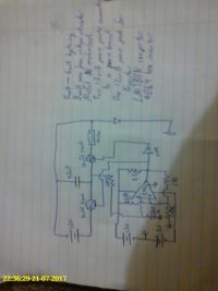
Plasma, Fri Jul 21 2017, 10:50AMHi, it I've built this circuit but when the voltage reaches 9 volt on the capacitor, and the comparator must have switched.
The comparator has a hysteria between 5_6volt.
Would the circuit work as is, I'm trying to charge up a capacitor then discharge it.
Thanks

Re: Problem with comparator and switching
2Spoons, Fri Jul 21 2017, 09:38PM
A sharp image would help. Better still go get one of the free SPICE simulators (e.g. LT SPICE, Simetrix, TI Tina) and use that as a drawing tool. You could also test your circuit with it ;) I use Simetrix - extensively.
2Spoons, Fri Jul 21 2017, 09:38PM
A sharp image would help. Better still go get one of the free SPICE simulators (e.g. LT SPICE, Simetrix, TI Tina) and use that as a drawing tool. You could also test your circuit with it ;) I use Simetrix - extensively.
Re: Problem with comparator and switching
Plasma, Sat Jul 22 2017, 07:34AM
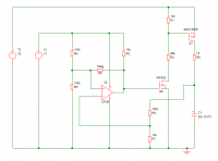
I've simulated it, and the capacitor shows a couple mV but the mosfet has 12v to the gate.
Ideas, cheers
Plasma, Sat Jul 22 2017, 07:34AM
I've simulated it, and the capacitor shows a couple mV but the mosfet has 12v to the gate.
Ideas, cheers
Re: Problem with comparator and switching
DerAlbi, Sat Jul 22 2017, 08:30AM
please attach the .asc as zip here.
Note that A1, the schmitt trigger inverter, does have default values of 0V Low, 1V High at its output. i doubt it can drive the IRF530 in its default form.
Have you checked that you get the voltages you wanted everywhere? If not do so!
Also for better readability use "110k", instead of "110000" (the capacitor is "30n" for example).
Then please simulate only the shortest time needed. The time step spice uses is somewhat related to the overall time - the longer you simulate the coarser the simulation by default..
Re: Problem with comparator and switching
Plasma, Sat Jul 22 2017, 09:27AM
I've attached the file
]picy.zip[/file]
Plasma, Sat Jul 22 2017, 09:27AM
I've attached the file
]picy.zip[/file]
Re: Problem with comparator and switching
DerAlbi, Sat Jul 22 2017, 09:49AM
you made R2 "1m" which is 1 MilliOhm. If you want to make some thing MegaOhm, you need to write "1Meg" in spice.
Again A1 issnt configured in any useful way. But besides that i cant really give you any advice. You still simulate for thousands of seconds...
Anyway, i looked at it, found some problems, but the overall circuit is a problem. the whole concept seems bad... i am honestly not sure what some stuff was supposed to mean...
I suggest you build a block diagram, figure out each block and see if the signal do what they are supposed to do..
]picc.zip[/file]
Re: Problem with comparator and switching
hen918, Sat Jul 22 2017, 02:45PM
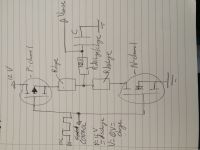
Yeah, I agree with DerAlbi, and, as I'm sure he has noticed, one of your MOSFETs is attatched to a positive source, yet it is an N-channel 'FET. Change it to a P-channel one, and then feed it with the same inverted signal as the other 'FET. Then when the signal from the comparitor is low, you will get it inverted to turn M2 on and M1 off.
Please also redraw the bit with the MOSFETs so they are the right way up: that circuit is almost invariably drawn vertically, with M2 on the bottom and M1 on the top.
Re: Problem with comparator and switching
Plasma, Sun Jul 23 2017, 04:10AM
Good advice. I've made the circuit more simple and also built it like the simple. Price in the built one the multimeter is showing 5.40volt across the capacitor, and I think it is working.
I would like to have a higher voltage source charging the capacitor but it will fry the comparator, and how would people go about taking a ratio of the capacitor voltage, the voltage divider wasn't working.
Re: Problem with comparator and switching
DerAlbi, Sun Jul 23 2017, 09:28AM
So you are discharging the 30uF through 200k and recharging it with a massive current pulse through he IRF530.with your 10u timestep, you might not see it, but this is kind of brutal. Please give M1 a 10R resistor on its source... its not mandatory, but good practice.
Regarding the "higher voltage": wrong architecture. It would be doable by a PFET.. of course you need a small NFET and a resistive divider to drive its gate, but it would work.
Re: Problem with comparator and switching
Plasma, Thu Jul 27 2017, 12:25PM
I've got this so far, I'm trying to get R5 below 10ohm,but it doesn't switch, I'm thinking there are multiple voltage dividers that stop it working. The gate to source, is close to 12volt.
How would I modified the circuit to make R5 about 10ohm.
Plasma, Thu Jul 27 2017, 12:25PM
I've got this so far, I'm trying to get R5 below 10ohm,but it doesn't switch, I'm thinking there are multiple voltage dividers that stop it working. The gate to source, is close to 12volt.
How would I modified the circuit to make R5 about 10ohm.
Re: Problem with comparator and switching
hen918, Thu Jul 27 2017, 02:41PM
I find it difficult to make out what is going on there. This was what I meant earlier:

EDIT: Click on it to see it the right way around and a decent size.
hen918, Thu Jul 27 2017, 02:41PM
I find it difficult to make out what is going on there. This was what I meant earlier:

EDIT: Click on it to see it the right way around and a decent size.
Re: Problem with comparator and switching
2Spoons, Thu Jul 27 2017, 11:30PM
Like this. part numbers are just defaults - this is to show you the topology, you can play with all the values to get what you want.
In a real circuit I would use a 12V TVS or Zener across the gate/source of the P-fet for safety.
Note that when simulating an unstable circuit like this you may need to specify some initial conditions - most probably on the capacitor. A transient sim starts with a DC operating point calculation, and with these sorts of circuits the simulator often needs a little help.
Also - please look at the way I and other members draw circuits, and try to emulate the logical flow you see. Some of your drawings have been very difficult to interpret.

Re: Problem with comparator and switching
Plasma, Sat Jul 29 2017, 06:42PM
Thanks guys, I placed a p, mosfet at the top driven by a second p, fet and a voltage divider sending the signal to a noninverting comparator.
It's working like I want it. Cheers
Plasma, Sat Jul 29 2017, 06:42PM
Thanks guys, I placed a p, mosfet at the top driven by a second p, fet and a voltage divider sending the signal to a noninverting comparator.
It's working like I want it. Cheers
Re: Problem with comparator and switching
Plasma, Sat Aug 05 2017, 05:23AM
My problem with the sim, I changed it to two Nmosfet with the top one driving a P. I'm still crunching data but I think this circuit is ready to test with the genny.
Will update the other thread, just not making the same ground solved it.
Thanks,
Plasma, Sat Aug 05 2017, 05:23AM
My problem with the sim, I changed it to two Nmosfet with the top one driving a P. I'm still crunching data but I think this circuit is ready to test with the genny.
Will update the other thread, just not making the same ground solved it.
Thanks,
Re: Problem with comparator and switching
Plasma, Sat Aug 05 2017, 05:51AM
I don't really understand the p mosfet, if I switch off ground then both p and n won't work, if I have ground, at drain for n and source for p, then a plus voltage will open n, but if the drain on p is open circuit then how will it open.
Sorry for the basic questions but the book doesn't explain it right or its me, that part doesn't matter.
Thanks
Re: Problem with comparator and switching
2Spoons, Sat Aug 05 2017, 06:41AM
To turn on a Pch MOSFET - make the gate more negative than the source.
I find your question incredibly difficult to understand - please draw a diagram of your connections.
2Spoons, Sat Aug 05 2017, 06:41AM
To turn on a Pch MOSFET - make the gate more negative than the source.
I find your question incredibly difficult to understand - please draw a diagram of your connections.
Re: Problem with comparator and switching
Plasma, Sat Aug 05 2017, 02:53PM
The mosfet isn't switching from 0=-13volt, it only moves about one volt.
Plasma, Sat Aug 05 2017, 02:53PM
The mosfet isn't switching from 0=-13volt, it only moves about one volt.
Re: Problem with comparator and switching
2Spoons, Sun Aug 06 2017, 12:49AM
your Pch mosfet is upside down. Source should be connected to positive rail.
The graph is meaningless to us unless you also tell us which node is being graphed. Use net labels on your schematic.
Show us Pch gate, Nch gate and capacitor voltage all on one graph. With appropriate labels.
Also its highly unlikely that a comparator will accept having its output pulled up to a voltage higher than its supply rails - thats why I put an Nch buffer in the schematic I showed you.
Re: Problem with comparator and switching
Plasma, Sun Aug 06 2017, 03:53AM
Modified it, is it ok to have two comparator like that, will there be problems with switching.
Edit
Just realised the 450kohm from the source was dropping it, changed it to275k and then 300kohm,its now 12volt.
Plasma, Sun Aug 06 2017, 03:53AM
Modified it, is it ok to have two comparator like that, will there be problems with switching.
Edit
Just realised the 450kohm from the source was dropping it, changed it to275k and then 300kohm,its now 12volt.
Re: Problem with comparator and switching
Plasma, Thu Aug 17 2017, 11:28AM
The circuit works good, but I'm trying to replace the mosfet with igbt, I've downloaded a Fairchild sub for ltspice, but I'm not sure, of the overview design with igbt, any help appreciate, thanks.
Plasma, Thu Aug 17 2017, 11:28AM
The circuit works good, but I'm trying to replace the mosfet with igbt, I've downloaded a Fairchild sub for ltspice, but I'm not sure, of the overview design with igbt, any help appreciate, thanks.
Print this page