
ZVS Flyback-driver - Eagle layout for pcb etching
Nestade, Tue Jul 18 2017, 06:47PMHello,
Unfortunately I'm a noob in PCB designing and electronics in general but I'd like to etch my own PCB for my ZVS flyback-driver.
I already tried creating this PCB however I'm always getting problems connecting the parts as my placement seems to be bad so I can't connect everything without using vias on a single-layer PCB.
So I'd like to ask if anyone has already created a layout for this circuit and could upload the eagle files, please.
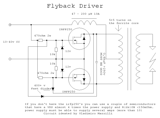
Source:

I already created the Eagle-schematic but I always fail connecting it without crossing connections and as I need thick traces it's not getting easier^^
I just uploaded the schematic (hope it's correct) - if anyone is bored or also needs the PCB it would be nice if you could create the layout and upload the files.
]zvs.zip[/file]
Thanks in advance! :)
Regards,
nestade
PS: I know there is already a thread but the last answer was in 2010 so i hope it's okay I created this new thread.
Re: ZVS Flyback-driver - Eagle layout for pcb etching
Sulaiman, Tue Jul 18 2017, 06:50PM
searching eBay uk for "zvs driver" gives 214 results at the moment :)
Sulaiman, Tue Jul 18 2017, 06:50PM
searching eBay uk for "zvs driver" gives 214 results at the moment :)
Re: ZVS Flyback-driver - Eagle layout for pcb etching
Nestade, Tue Jul 18 2017, 07:53PM
Hi,
Well this are populated PCBs and not layouts.
I'm trying to etch my own PCB as I got everything to make it on my own (except the Layout^^).
I already tried to use the parts-placement of the ebay-boards but I still got problems - I don't know if the PCBs on eBay are double-sided or if I'm just too stupid^^
Regards,
Nestade
Nestade, Tue Jul 18 2017, 07:53PM
Sulaiman wrote ...
searching eBay uk for "zvs driver" gives 214 results at the moment :)
searching eBay uk for "zvs driver" gives 214 results at the moment :)
Hi,
Well this are populated PCBs and not layouts.
I'm trying to etch my own PCB as I got everything to make it on my own (except the Layout^^).
I already tried to use the parts-placement of the ebay-boards but I still got problems - I don't know if the PCBs on eBay are double-sided or if I'm just too stupid^^
Regards,
Nestade
Re: ZVS Flyback-driver - Eagle layout for pcb etching
hen918, Wed Jul 19 2017, 01:48PM
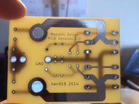
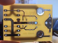
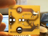
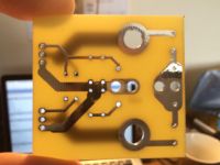
Here are some pictures of Mazzilli PCBs I designed a while ago, I can't find the files, sorry.
Looking from the left of the first picture to the right:
1 V++ in with the two through-holes for extra power;
2 the two large resistors go horizontally across in between the big through-holes at the top and bottom.
3 The big through-holes are the output, and big enough for small copper pipe for watercooling.
4 There is then the ground in the middle, a stupid revision error meant there is only one.
5 The resistors and zenners go next, vertically, pointing outward from the middle.
6 the UF diodes go here, pointing down then up.
7 then the MOSFETs. there is space for two pairs if required.
there are two versions of the board, one has 2* pairs of TO-247 'FETs and the other a single pair of TO-220s.


Print this page