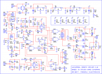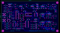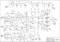
Franzoli electronics UD 3.0
wikus, Sat Jun 24 2017, 07:09PMHi Guys
Has anybody looked at this new driver from Franzoli electronics. He only has a Facebook site. No details on the driver.


Re: Franzoli electronics UD 3.0
Finn Hammer, Sat Jun 24 2017, 10:44PM
No.
Have you had a look at this driver:

it is the one you'd better use.....
Cheers, Finn Hammer
Finn Hammer, Sat Jun 24 2017, 10:44PM
wikus wrote ...
Hi Guys
Has anybody looked at this new driver from Franzoli electronics. He only has a Facebook site. No details on the driver.
Hi Guys
Has anybody looked at this new driver from Franzoli electronics. He only has a Facebook site. No details on the driver.
No.
Have you had a look at this driver:

it is the one you'd better use.....
Cheers, Finn Hammer
Re: Franzoli electronics UD 3.0
futurist, Sat Jun 24 2017, 11:04PM
Steve Ward made PSoC based UD3 several years ago

futurist, Sat Jun 24 2017, 11:04PM
Steve Ward made PSoC based UD3 several years ago

Re: Franzoli electronics UD 3.0
hen918, Sat Jun 24 2017, 11:33PM
Yeah, never trust an engineer that draws GND sideways or upside down. :)
Exactly how does Franzoli claim to improve on Steve's design?
hen918, Sat Jun 24 2017, 11:33PM
Yeah, never trust an engineer that draws GND sideways or upside down. :)
Exactly how does Franzoli claim to improve on Steve's design?
Re: Franzoli electronics UD 3.0
Alex Yuan, Sun Jun 25 2017, 07:39PM
It's the third revision of his drivers, not to be confused with the UD's. This version looks to have phase lead over his last universal driver. Though it's almost identical to a UD2.1/2.5 with a pulse width limiter.

Alex Yuan, Sun Jun 25 2017, 07:39PM
It's the third revision of his drivers, not to be confused with the UD's. This version looks to have phase lead over his last universal driver. Though it's almost identical to a UD2.1/2.5 with a pulse width limiter.

Re: Franzoli electronics UD 3.0
johnf, Mon Jun 26 2017, 09:30AM
Badly drawn circuits usually mean bad design
A circuit should flow and not grate on the nerves
I note 1n5819 s why not UF 1n4007 followed by a transil to clip the inevitable rogue pulse at some extended voltage that is going to turn the OCD amplifier into silicon oxide.
I started bottom left of the SCH and stopped there after seeing that, bound to be more gotchas in the rest
Re: Franzoli electronics UD 3.0
hen918, Mon Jun 26 2017, 11:10AM
Yeah, he seems to be relying on the diodes to have sufficient internal impedance to damp the leading edge current spikes. Putting a resistor in series and capacitor in parallel to form a low pass filter would be far more effective than leaving them both in parallel.
Edit: and on further inspection, the lower MOSFETs on the deplorably drawn H-Bridge lack pull-down resistors.
Edit 2: (I should really stop looking at this circuit) When the feedback isn't connected / high impedance the 100k potential divider will pull the voltage on the NOT gate to ~2.5V which is on the borderline of being indeterminate.
hen918, Mon Jun 26 2017, 11:10AM
johnf wrote ...
...
I note 1n5819 s why not UF 1n4007 followed by a transil to clip the inevitable rogue pulse at some extended voltage that is going to turn the OCD amplifier into silicon oxide.
...
...
I note 1n5819 s why not UF 1n4007 followed by a transil to clip the inevitable rogue pulse at some extended voltage that is going to turn the OCD amplifier into silicon oxide.
...
Yeah, he seems to be relying on the diodes to have sufficient internal impedance to damp the leading edge current spikes. Putting a resistor in series and capacitor in parallel to form a low pass filter would be far more effective than leaving them both in parallel.
Edit: and on further inspection, the lower MOSFETs on the deplorably drawn H-Bridge lack pull-down resistors.
Edit 2: (I should really stop looking at this circuit) When the feedback isn't connected / high impedance the 100k potential divider will pull the voltage on the NOT gate to ~2.5V which is on the borderline of being indeterminate.
Re: Franzoli electronics UD 3.0
teravolt, Mon Jun 26 2017, 01:51PM
and what difference is this over ud2.7 other than a pcb with through hole components. I wonder if they have permition to release it.
teravolt, Mon Jun 26 2017, 01:51PM
and what difference is this over ud2.7 other than a pcb with through hole components. I wonder if they have permition to release it.
Re: Franzoli electronics UD 3.0
futurist, Mon Jun 26 2017, 02:05PM
Object like circuit board or schematics can't be copyrighted
futurist, Mon Jun 26 2017, 02:05PM
Object like circuit board or schematics can't be copyrighted
Print this page