
Tuning a QFH antenna by measuring return loss
uzzors2k, Mon Feb 13 2017, 06:20PMI was wondering how one should go about tuning a QFH antenna by measuring it's return loss. Has anyone attempted this? I have this idea that if I move the two resonance points closer together, I'll increase the gain at the main reception frequency. This doesn't appear to be the case, but how does it affect the polarization? Will I lose circular polarization by doing this?
In the plots below I've shortened the larger loop, and eventually the smaller loop to raise the resonance frequency of each. The results are shown in three steps. Judging by the plots I've only reduced the antennas ability to receive around 120MHz.
The one plot is mislabeled by the way.
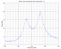
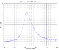
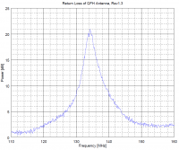
Re: Tuning a QFH antenna by measuring return loss
johnf, Mon Feb 13 2017, 06:54PM
Antenna gain is not the same as mismatch loss.
You have increased the Q of your antenna this does not mean more gain
however your antenna mod helps remove out of band signals
johnf, Mon Feb 13 2017, 06:54PM
Antenna gain is not the same as mismatch loss.
You have increased the Q of your antenna this does not mean more gain
however your antenna mod helps remove out of band signals
Re: Tuning a QFH antenna by measuring return loss
Hazmatt_(The Underdog), Tue Feb 14 2017, 03:16AM
If you can get a directional coupler you can measure your return loss.
In the forward direction you measure your forward power, reversed is return loss.
A simple 20dB directional coupler is a 10:1 ratio (basically a CT), and with two cores or a binocular core you can make a dual directional coupler to measure fwd and reverse power at the same time, and possibly calculate your VSWR.
Or you could just buy a dual directional coupler from Minicircuits. They have a lot of neat parts.
Re: Tuning a QFH antenna by measuring return loss
WaveRider, Tue Feb 14 2017, 04:13PM
You can tune the return loss by varying the relative size of the two loops, but be aware that the loop sizes are such that you get the proper phasing for circular polarization. (This is much like the "nearly square" method of generating circular polarization in microstrip patch antennas.) One loop is slightly below resonance and the other slightly above, to get the 90 degree phase shift between the loops.
I guess you are trying to build an antenna for the 137.5 MHz weather satellite facsimile downlink. There are many examples of these antennas out there in Google-land, as you probably know. Or take a known design on another frequency and scale for wavelength. Here is an article that I wrote for my job a couple of years ago on the topic. Basics of Quadrifilar Helix Antennas
Cheers!
Re: Tuning a QFH antenna by measuring return loss
uzzors2k, Wed Feb 15 2017, 06:49PM
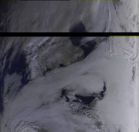
Thanks for the replies. I should have included some more information in the first post. What I did was measure the return loss by following the procedure outlined here , using a mini-circuits directional coupler. I've also made plots of the VSWR, which I've included now. The antenna is indeed for weather satellite reception, so I'm only aiming to receive signals between 137-138MHz. It has worked quite well, here's a Meteor M2 pass I received this Sunday. I'm located roughly in Oslo, and the satellite was southbound, passing to the east. So I guess one can infer where a null in my reception is. I've also been able to receive passing NOAA satellites, which seem to have a stronger signal (probably due to lower bandwidth?).
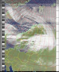
Excellent article Waverider, I'll have to read it more thoroughly. I based my design on one of the calculators out there, which is what the rev 1.0 results are from. Based on my Tesla coil days, I knew I wouldn't get the antenna right without some tuning afterwards. So from my plots, it would I appear I've improved the selectivity. Is there any way I can check if the phasing/polarization is still correct? And can my modifications impact the radiation pattern, or is it given more by the form of the two loops, rather than conductor lengths?
]vswr_qfh_rev1_narrowband.pdf[/file]
]vswr_qfh_rev1.2_narrowband.pdf[/file]
uzzors2k, Wed Feb 15 2017, 06:49PM
Thanks for the replies. I should have included some more information in the first post. What I did was measure the return loss by following the procedure outlined here
 , using a mini-circuits directional coupler. I've also made plots of the VSWR, which I've included now. The antenna is indeed for weather satellite reception, so I'm only aiming to receive signals between 137-138MHz. It has worked quite well, here's a Meteor M2 pass I received this Sunday. I'm located roughly in Oslo, and the satellite was southbound, passing to the east. So I guess one can infer where a null in my reception is. I've also been able to receive passing NOAA satellites, which seem to have a stronger signal (probably due to lower bandwidth?).

Excellent article Waverider, I'll have to read it more thoroughly. I based my design on one of the calculators out there, which is what the rev 1.0 results are from. Based on my Tesla coil days, I knew I wouldn't get the antenna right without some tuning afterwards. So from my plots, it would I appear I've improved the selectivity. Is there any way I can check if the phasing/polarization is still correct? And can my modifications impact the radiation pattern, or is it given more by the form of the two loops, rather than conductor lengths?
]vswr_qfh_rev1_narrowband.pdf[/file]
]vswr_qfh_rev1.2_narrowband.pdf[/file]
Print this page