
large inductance measurements of Leybold coils (from 1uH up to 1 kH)
Physikfan, Sat Jan 28 2017, 03:37PMI would like to post some data of measurements of large inductances,
but I have no idea how to present the data in a format similar to an exel sheet.
Please, could somebody give me some hints?
Regards
Physikfan
Re: large inductance measurements of Leybold coils (from 1uH up to 1 kH)
Sulaiman, Sat Jan 28 2017, 05:57PM
just a note,
often the easiest way to measure large inductances is to;
pass a known dc current through the inductor,
'catch' the flyback with a capacitor via a suitable diode
measure voltage across capacitor, .... calculate
based on E = 0.5 x L x I x I for inductor, E = 0.5 x C x V x V for a capacitor.
Re: large inductance measurements of Leybold coils (from 1uH up to 1 kH)
Bjørn, Sat Jan 28 2017, 11:07PM
Watch your fingers when doing this. It is easy to get too relaxed when working with low voltages, a large inductor can be extremely unpleasant when it suddenly releases its stored energy.
Bjørn, Sat Jan 28 2017, 11:07PM
Watch your fingers when doing this. It is easy to get too relaxed when working with low voltages, a large inductor can be extremely unpleasant when it suddenly releases its stored energy.
Re: large inductance measurements of Leybold coils (from 1uH up to 1 kH)
Dr. Slack, Sun Jan 29 2017, 05:02AM
do you mean, like this?
which is cut'n'paste a text file of fixed width columns between code tags, the <> button
Or you could attach the text file itself, or an excel file that's been printed to pdf
Attach a png screenshot of a excel file being displayed works as well.
Dr. Slack, Sun Jan 29 2017, 05:02AM
do you mean, like this?
sample   inductance    seriesR
 01       103.2H        1.3ohm
 02        18.7kH      12.3ohm
which is cut'n'paste a text file of fixed width columns between code tags, the <> button
Or you could attach the text file itself, or an excel file that's been printed to pdf
Attach a png screenshot of a excel file being displayed works as well.
Re: large inductance measurements of Leybold coils (from 1uH up to 1 kH)
Physikfan, Sun Jan 29 2017, 06:28PM
Hi Dr. Slack, Bjørn, Patrick and Sulaiman
The data should have the format which I will present in my next posting.
To create this jpg I had to copy the table into the program paint.
But doing so it is extremely difficult to correct even one number only.
Are there more simple procedures possible?
Regards
Physikfan
Re: large inductance measurements of Leybold coils (from 1uH up to 1 kH)
Physikfan, Sun Jan 29 2017, 08:32PM
Large coils have something fascinating:
1. The opening spark, which when switched off, reflects the magnetic energy stored in the coil.
2. The slow current increase at power up, which may take up to a few seconds.
3. With a capacitor of 50 μF, a free attenuated resonant circuit of about 1 Hz can be realized.
However, reliable values ​​for the inductance L in large coils can not be determined so easily.
I would therefore like to try to animate members of this forum, to present their own measurements on large inductors.
They should also explain their methods of measuring L and also mention any problems.
For my part, I would like to present measurements on relatively world wide easily accessible Leybold coils.
Measurements of the inductances of the coils of Leybold with LCR meter Agilent 4236B, 1 V amplitude, measuring frequency 120 Hz.
Overview of Leybold Coils
Cat.-No.,
562 19 coil with 5 turns, load 500 A, wire thickness 8.0 mm Ø
562 18 coil with 50 turns, permanent load 10 A, wire thickness 2.0 mm Ø
562 13 Coil with 250 turns, permanent load 5 A, wire thickness 1.5 mm Ø
562 14 Coil with 500 turns, permanent load 2.5 A, wire thickness 1.0 mm Ø
562 15 Coil with 1 000 turns, permanent load 1,25 A, wire thickness 0,7 mm Ø
562 16 Coil with 10 000 turns, permanent load 0,1 A, wire thickness 0,2 mm Ø
562 17 Coil with 23 000 turns, permanent load 0,02 A, wire thickness 0,1mm Ø

Not all measurements showed meaningful results, note the unfilled places in the matrix.
Physikfan, Sun Jan 29 2017, 08:32PM
Large coils have something fascinating:
1. The opening spark, which when switched off, reflects the magnetic energy stored in the coil.
2. The slow current increase at power up, which may take up to a few seconds.
3. With a capacitor of 50 μF, a free attenuated resonant circuit of about 1 Hz can be realized.
However, reliable values ​​for the inductance L in large coils can not be determined so easily.
I would therefore like to try to animate members of this forum, to present their own measurements on large inductors.
They should also explain their methods of measuring L and also mention any problems.
For my part, I would like to present measurements on relatively world wide easily accessible Leybold coils.
Measurements of the inductances of the coils of Leybold with LCR meter Agilent 4236B, 1 V amplitude, measuring frequency 120 Hz.
Overview of Leybold Coils
Cat.-No.,
562 19 coil with 5 turns, load 500 A, wire thickness 8.0 mm Ø
562 18 coil with 50 turns, permanent load 10 A, wire thickness 2.0 mm Ø
562 13 Coil with 250 turns, permanent load 5 A, wire thickness 1.5 mm Ø
562 14 Coil with 500 turns, permanent load 2.5 A, wire thickness 1.0 mm Ø
562 15 Coil with 1 000 turns, permanent load 1,25 A, wire thickness 0,7 mm Ø
562 16 Coil with 10 000 turns, permanent load 0,1 A, wire thickness 0,2 mm Ø
562 17 Coil with 23 000 turns, permanent load 0,02 A, wire thickness 0,1mm Ø

Not all measurements showed meaningful results, note the unfilled places in the matrix.
Re: large inductance measurements of Leybold coils (from 1uH up to 1 kH)
Sulaiman, Sun Jan 29 2017, 09:37PM
given the low 2.pi.F.L/R of these inductors
and the non-linearity of the iron core B vs H
and frequency dependence of the core loss factor
specifying and/or parameterizing inductors is non-trivial.
Usually it is best to test in its intended circuit at its intended rating,
or, to standardize results, you could provide each of us with a 4236B

Re: large inductance measurements of Leybold coils (from 1uH up to 1 kH)
Patrick, Sun Jan 29 2017, 09:54PM
Dont kill yourself. please.
Patrick, Sun Jan 29 2017, 09:54PM
Dont kill yourself. please.
Re: large inductance measurements of Leybold coils (from 1uH up to 1 kH)
Physikfan, Mon Jan 30 2017, 10:01AM
Examples for the investigated Leybold coils:
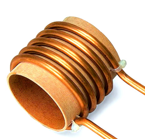
Coil with 5 turns
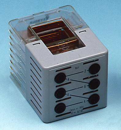
Coil with 50 turns
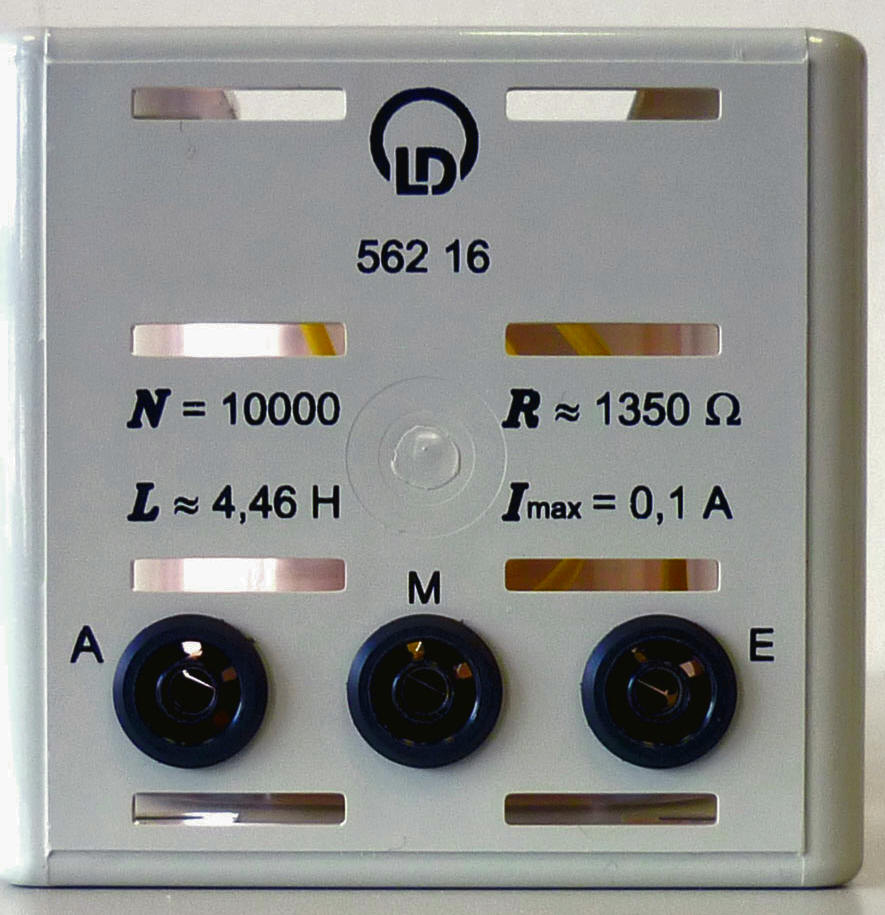
Coil with 10000 turns
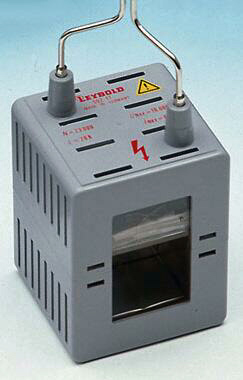
Coil with 23000 turns
Physikfan, Mon Jan 30 2017, 10:01AM
Examples for the investigated Leybold coils:

Coil with 5 turns

Coil with 50 turns

Coil with 10000 turns

Coil with 23000 turns
Re: large inductance measurements of Leybold coils (from 1uH up to 1 kH)
Physikfan, Wed Feb 01 2017, 09:05AM
New measurements of the inductances of the Leybold coils with LCR meter GW Instek LCR 817, 1 V amplitude, measuring frequencies 12 Hz and 120 Hz.
Note the large available range of the inductances (from about 1 uH to about 1kH)!
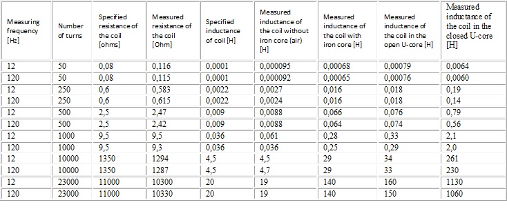

To compare these new measurements (Instek LCR) with the old measurements (Agilent 4236B), the old measurements at the measuring frequency of 120 Hz are shown again.
I am looking forward to your comments!
Physikfan, Wed Feb 01 2017, 09:05AM
New measurements of the inductances of the Leybold coils with LCR meter GW Instek LCR 817, 1 V amplitude, measuring frequencies 12 Hz and 120 Hz.
Note the large available range of the inductances (from about 1 uH to about 1kH)!


To compare these new measurements (Instek LCR) with the old measurements (Agilent 4236B), the old measurements at the measuring frequency of 120 Hz are shown again.
I am looking forward to your comments!
Re: large inductance measurements of Leybold coils (from 1uH up to 1 kH)
Dr. Slack, Wed Feb 01 2017, 10:26AM
Apparent inductance will change with measurement frequency due to the self capacitance effects. The self capacitance appears in parallel, which will raise the apparent inductance, that is reduce the susceptance, as the frequency approaches the SRF (self resonant frequency). It will be worth measuring the SRF of all the coils, this is most conveniently done with a signal generator and an oscilloscope.
Re: large inductance measurements of Leybold coils (from 1uH up to 1 kH)
Physikfan, Wed Feb 01 2017, 12:27PM
Hi Dr.Slack
The self resonant frequency (2*PI*f)srf of an inductance means exactly the value where 2*PI*f*L = 1/(2*PI*f*C),
C corresponds to stray capacitance, winding capacitance etc.?
And the inductance at this frequency is purely resistive, therefore the current trough the coil as a function of the frequency has its maximum value, experiment with a sine oscillator and oscilloscope?
That means if you want to measure the "real" effective inductance the measuring frequency should be very low compared to the self resonant frequency?
Re: large inductance measurements of Leybold coils (from 1uH up to 1 kH)
Uspring, Wed Feb 01 2017, 02:38PM
Physikfan: To the lowest order, the coil appears as a parallel tank. The current through the coil has its _minimum_ at resonance. At low frequency the stray capacitance has the lowest effects.
Uspring, Wed Feb 01 2017, 02:38PM
Physikfan: To the lowest order, the coil appears as a parallel tank. The current through the coil has its _minimum_ at resonance. At low frequency the stray capacitance has the lowest effects.
Re: large inductance measurements of Leybold coils (from 1uH up to 1 kH)
Plasma, Wed Feb 01 2017, 03:23PM
Physician, the resistance to the inductor would have a large effect on the amps from the power supply. If you treat the resistance in parallel..
2*3.142*120*1024 = 772178 Xl
2*3.142*12*1130 = 85,211 Xl
Vin*(Xl^2/1100) is the amps from the source at high frequency more current will be drawn from the supply, showing a smaller inductor,
The resonance frequency would be 1/(6.284*sqrt(L*C)
Stray capacitance Screen = 1/1024 *(1/6.284*120)^2
If you can find the resonance frequncy, and use that frequency you should be able to get pretty accurate values
Just my 2 cents
Re: large inductance measurements of Leybold coils (from 1uH up to 1 kH)
Physikfan, Wed Feb 01 2017, 08:21PM
Hi Sulaiman, Bjørn, Patrick, Dr. Slack, Uspring and Plasma
Many thanks for your comments and hints.
I think I could learn a lot on this subject.
My next step will be to measure the self resonant frequencies of all these Leybold coils.
Ad Plasma
Are looking at the coil with 23 000 turns, right?
"If you treat the resistance in parallel..
2*3.142*120*1024 = 772178 Xl"
2*PI*120*1024, do you mean Omega*L, but, please, from where you get this 1024?
"2*3.142*12*1130 = 85,211 Xl" this is 2*Pi*f*L(23000 at 12 Hz) okay
"Vin*(Xl^2/1100)" please, from where you get this 1100? I do not understand this equation.
"Stray capacitance Screen = 1/1024 *(1/6.284*120)^2"
What I understand is:
If I measure the resonance frequency then I can calculate the stray capacitance of this special coil (23000 turns), right?
Regards
Physikfan
Re: large inductance measurements of Leybold coils (from 1uH up to 1 kH)
Plasma, Thu Feb 02 2017, 02:17AM
Sorry 1024 should be 1060. The 11000 is the resistance of the coil, you treat that with the power two of the inductor impedance. The resistance of the coil is treated as parallel to both the stray capacitance and induction. Three leg parallel. It gets added to the inductor, and that is times with capacitor.
Prf = (RsL+XL)+ XC. / (RsL+XL)*XC
It doesn't change the real resonance frequency by much
If the frequncy is 50000, and the voltage of the power supply is 10v, you measure 100mA
10v/.1=ans*11000=sqrt(ans)= inductor.
Re: large inductance measurements of Leybold coils (from 1uH up to 1 kH)
Dr. Slack, Thu Feb 02 2017, 07:22AM
The SRF is 1/2.pi.sqrt(L.C) in Hz, where L and C are the DC inductance and the coil effective self capacitance respectively.
If you measure the inductance well below this frequency, say a factor of 10 below, then the error from the self capacitance is of the order of this factor squared for factor of 10.
Resonance is most easily detected by connecting a high impedance scope to the coil, and using a high value resistor to a signal generator, then sweeping the frequency until you get a maximum AC voltage (minimum current). Don't forget that the scope will add some extra capacitance to ground.
Although at resonance you can model the loss to be due to either a series or a parallel resistor, a resistor in series with the L matches more closely what you can measure at DC as the copper resistance. The equivalent parallel resistor is rather different in value. The effective resistance at resonance will be a little different from the DC value due to skin and proximity effects reducing the area of the wire available for conduction.
A good alternative way to make your inductance measurements is to load the coil with a capacitor, and sweep for resonance. A plot of frequency and capacitance will allow you to estimate the self capacitance that is always in parallel with the added C. This allows you to measure at any frequency you have capacitors for.
You can estimate the losses at resonance by measuring the Q factor, which is the centre frequency / 3dB bandwidth. Don't forget that the 'high value resistor' that you use to connect to the sig-gen, and the scope input resistance, will also contribute to parallel loading of the LC.
Print this page