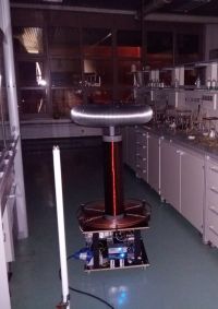
My first DRSSTC
futurist, Thu Jan 05 2017, 07:07PMHi everyone,
I'm new here and I come from Croatia
I wanted to have a Tesla coil since I saw one at the tehnical museum as a kid, so a few months ago I decided to try to make a DRRSTC
Now after reading most of what I could find about DRSSTCs on the Internet I need some help finishing the coil
I was stupid enough to start with the UD2.7C driver so this turned to a quite difficult project for me, I have little experience in electronics (studiying chemistry) so excuse me if I ask stupid questions :)
After receiving UD27C PCB from loneoceans I went to source all the other components - for the IGBT I decided to try the CM200DY-24NF
which was the cheapest IGBT brick I could find (62 $ with shipping from aliexpress), so this led to a halfbridge medium sized coil with 240 V AC voltage doubler.
The design I have choosen is something between loneoceans DRSSTC 2, Steve Ward's DRSSTC 1 and Kaizer's DRSSTC I
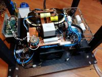
After 3 months worth of weekends I finally put most parts together, these are the specs:
Topload
130 x 620 mm from flexible aluminum tube with 2x 400 mm diameter stainless steel serving plates
Secondary coil
160 mm diameter on PVC drain pipe, ~2200 turns (~605 mm long), 0.25 mm double enamelled copper wire
2x polyester resin coated (epoxy is around 10x more expensive here), turned pretty bad with lots of bubbles but ok for my first try
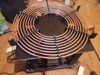
Primary coil
8 mm diameter soft copper tubing (1 mm thick), 257 mm inner diameter, ~9 turns with 10 mm spacing (too large inner diameter?)
3x 3 mm plywood supports glued together with PVA, used metal screws to secure them
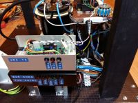
Electronics
Input 240 V AC with the voltage doubler
KBPC5010 1000 V 50 A bridge rectifier with 2x EPCOS 4700 uF 400 V caps
All bridge connections made with 15 x 3 mm copper bus bar
MMC air-cooled 12x 942C20P15K-F capacitors with 10 Mohm 1/4 W balancing resistors for 0.45 uF at 4000 V DC
Halfbridge CM200DY-24NF sitting on air-cooled 1.5 kg copper plate, IGBT snubber 1 uF 1200 V + 0.15 uF 2000 V DC parallel on the bus capacitors
Old CPU cooler fit nicely under the copper plate allowing IGBT to be mounted horizontally
0.10 uF 2000 V DC capacitor from negative rail to grounded copper heatsink
10 kohm 20 W resistor is connected accros the output of the inverter
Connections bridge to MMC and to primary are made with the 16 mm^2 welding cable
Universal driver 2.7C with 24 V switching PSU, 2x 1:~625 CTs wound on high permeability core
13 turns 1:1:1 GDT N87 core with ferrite bead, gate resistors 4.7 ohm 1/2 W, gates and emitters shorted with 1.5KE33CA TVS (Are the TVS ok? It was the only one I could buy locally)
I have calculated the power rating for the gate resistor to be 4.7 W - it seems high and I have just 1/2 W resistors available, can this cause problems?
formula: P = 1350 * 10^-9 C * 50 V * 70000 s^-1
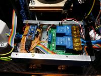
Bus precharger and fan speed controller (LM35-DZ temp. sensors) are made with Arduino nano 328A, 2x 30 A relays and 150 ohm (charge) + 1 kohm (discharge) 10 W resistors.
The interrupter was made by my friend - it's Arduino nano 328A with modified oneTesla interrupter code for playing MIDI directly from USB + 10 m ST-ST 125/62.5 um optic cable
I made a mistake with the primary radius while making it so the coupling coeffitient is 0.128 vs recomended 0.136
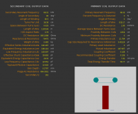
JavaTC output is below
Are my specs ok and is this going to work?
Any advice is appreciated
Re: My first DRSSTC
zzz_julian_zzz, Fri Jan 06 2017, 05:31AM
Hi and Welcome..
For a first timer, I can say that your work is impressive :) my opinion is that it is ready to be tested and fired up.
Here are some expectation from your end before operating:
1. to have idea on SSTC and DRSSTC works
2. to ensure the UD2.7C is working properly using interrupter function gen and oscilloscope
3. to ensure you have checked the GDT phasing on the bridge, via scope (check V max, waveform shape, frequency, phase lead)
4. to slowly ramp the AC input voltage on your first run (test first only ¼ of the max voltage) – VARIAC will help
5. to monitor the Primary Coil current thru winded CTs(with burden) – using oscilloscope
6. to monitor the Primary frequency to be close as what you have simulated, check the wave shape – remove notching later for higher power transfer
7. to activate the OCD Protection leveled to a not so high current limit
8. to ensure your interrupter is working ok - verified via scope, start to low BPS and from 0 us On time
9. to use break out point
10. to install ground strike rail
here are some answers to your Q:
1. Prim Inner diameter is ok, coupling should be your consideration (0.128 is fine) – just start with low V input at first run to check whether the two coils flashes over, then ramp slowly
2. TVS 33V are ok – I don’t use these actually
3. 1 to ½ watt gate resistors are ok – what is the resistance value?
My Q:
1. Why Primary Cap is so high? 0.45 uF – but as long as you are using OCD protection and you are monitoring the current via oscilloscope on your first run, then its ok.. Don’t play too long ON Times in your interrupter as I believe your coil has very low zurge impedance.
2. What ON time you plan to use?
Re: My first DRSSTC
Hydron, Fri Jan 06 2017, 11:27AM
As I mentioned to futurist earlier on IRC, this is a very impressive start to coiling!
.45uF does sound a little big, though it will help getting decent primary currents using a half bridge design. The DC rating of 4kV is maybe a little low, i would suggest limiting the current to ~600A to avoid going over the DC rating.
If the primary is large enough you may be able to reconfigure the MMC to 4 parallel, 3 series for .2uF at 6kV DC. Would need to move the primary tap further out, and if you run out of turns the resulting frequency will be higher than before, but this may not be a bad thing if upper pole tuning works well for your coil, and would increase the coupling a bit too.
Re: My first DRSSTC
futurist, Fri Jan 06 2017, 12:52PM
For the primary capacitor I considered using 9x 942C for 0.15 uF 9 kV or 12x 942C for 0.45 uF 4 kV.
I choose the 0.45 uF variation because it is used here

and here

JavaTC says 7.3888 turns for 0.20 uF primary, I have almost 9 turns so I can try.
I'll install the strike rail, make primary tap and then borrow an osciloscope and a function generator. I couldn't find 1:1 transformer but I have 1:2 ~500 VA. Can I use it with variac?
Without an osciloscope I could only verify that the UVLO is working, the interrupter turns the signal LED on so that part also works. For the signal LED I installed a HE green LED, but at 100 uS ontime it's not quite bright, is that normal?
I marked the GDT secondary leads and connected them antiphase, but I'll doublecheck. I stripped the CAT5 cable with a lighter to avoid scoring the wire.
The interrupter on time is from 10 to 100 uS, maybe higher for the MIDI but for now I won't be using that.
Do I have to make a separate CT or I can use existing one and how? Can you explain shortly?
futurist, Fri Jan 06 2017, 12:52PM
For the primary capacitor I considered using 9x 942C for 0.15 uF 9 kV or 12x 942C for 0.45 uF 4 kV.
I choose the 0.45 uF variation because it is used here

and here

JavaTC says 7.3888 turns for 0.20 uF primary, I have almost 9 turns so I can try.
I'll install the strike rail, make primary tap and then borrow an osciloscope and a function generator. I couldn't find 1:1 transformer but I have 1:2 ~500 VA. Can I use it with variac?
Without an osciloscope I could only verify that the UVLO is working, the interrupter turns the signal LED on so that part also works. For the signal LED I installed a HE green LED, but at 100 uS ontime it's not quite bright, is that normal?
I marked the GDT secondary leads and connected them antiphase, but I'll doublecheck. I stripped the CAT5 cable with a lighter to avoid scoring the wire.
The interrupter on time is from 10 to 100 uS, maybe higher for the MIDI but for now I won't be using that.
5. to monitor the Primary Coil current thru winded CTs(with burden) – using oscilloscope
Do I have to make a separate CT or I can use existing one and how? Can you explain shortly?
Re: My first DRSSTC
loneoceans, Sat Jan 07 2017, 01:24AM
Futurist, good work on the coil. Here are some comments in no particular order:
1) Your capacitor bank is only rated 1000VAC, and in fact less due to the high frequencies we’re running the coils at. This will certainly lead to premature MMC failure quickly at any sort of high current rating. Your primary has about a 5.1 ohm impedance. The CM200NF bridge should be able to do 500A but at that rating you’re seeing a 2.5kApk which is far over the RMS AC rating. So you'll need to adjust the current limit for the maximum capacitor voltage. I’d recommend at the very least dropping to a 200nF 1.5kVAC configuration or have 4 or 5 of the CDE caps in series and making more strings of them. It’s more expensive at first, but it’ll save you the trouble of dealing with popped MMCs later.
2) The signal LED corresponds to the actual ON signal. So 100us on-time at 200Hz Is just 2% duty cycle, so your LED will appear to be 2% as bright as it’s supposed to be. I.e. it’s normal for it to look dim. You can either use a brighter LED or change the series resistor (add another SMD one on top) to increase the LED brightness.
3) I’d recommend buying a proper current probe like an Ion Physics one or a Pearson on ebay if you can find a good deal. Otherwise the easiest is to just make another CT like the one you’ve made, and terminate the ends of the secondary with some known resistor. You can probe across the resistor and to get a measurement of the current (I = V/R).
4) You’ll find that at low power, a roughly equal primary and secondary frequency leads to good results. At high power, it’s usually good to detune the primary such that it is about 5 to 10% lower in frequency than the secondary. When the spark grows it adds capacitance and drops the secondary frequency.
5) If you’re going to probe gate drive and inverter outputs to tune phase lead on the UD2.7C (as outlined in my DRSSTC 3 page here , I’d recommend using not only a variac to ramp up power to the bus, but also it’s important to keep the bus isolated for your safety and to avoid ground loops. You can use an isolation transformer for that. Alternatively, a high voltage DC power supply is good as well. Typically I tune for phase lead without the secondary in place.
6) The 1.5ke33ca TVSes are fine. You can go even lower like a 1.5ke25. 1/2W gate resistors should work fine, but why not just use 4 of them to get a 2W resistor :).
The other feedback from Hydron and Julian are great as well. Good luck!
loneoceans, Sat Jan 07 2017, 01:24AM
Futurist, good work on the coil. Here are some comments in no particular order:
1) Your capacitor bank is only rated 1000VAC, and in fact less due to the high frequencies we’re running the coils at. This will certainly lead to premature MMC failure quickly at any sort of high current rating. Your primary has about a 5.1 ohm impedance. The CM200NF bridge should be able to do 500A but at that rating you’re seeing a 2.5kApk which is far over the RMS AC rating. So you'll need to adjust the current limit for the maximum capacitor voltage. I’d recommend at the very least dropping to a 200nF 1.5kVAC configuration or have 4 or 5 of the CDE caps in series and making more strings of them. It’s more expensive at first, but it’ll save you the trouble of dealing with popped MMCs later.
2) The signal LED corresponds to the actual ON signal. So 100us on-time at 200Hz Is just 2% duty cycle, so your LED will appear to be 2% as bright as it’s supposed to be. I.e. it’s normal for it to look dim. You can either use a brighter LED or change the series resistor (add another SMD one on top) to increase the LED brightness.
3) I’d recommend buying a proper current probe like an Ion Physics one or a Pearson on ebay if you can find a good deal. Otherwise the easiest is to just make another CT like the one you’ve made, and terminate the ends of the secondary with some known resistor. You can probe across the resistor and to get a measurement of the current (I = V/R).
4) You’ll find that at low power, a roughly equal primary and secondary frequency leads to good results. At high power, it’s usually good to detune the primary such that it is about 5 to 10% lower in frequency than the secondary. When the spark grows it adds capacitance and drops the secondary frequency.
5) If you’re going to probe gate drive and inverter outputs to tune phase lead on the UD2.7C (as outlined in my DRSSTC 3 page here
 , I’d recommend using not only a variac to ramp up power to the bus, but also it’s important to keep the bus isolated for your safety and to avoid ground loops. You can use an isolation transformer for that. Alternatively, a high voltage DC power supply is good as well. Typically I tune for phase lead without the secondary in place.
6) The 1.5ke33ca TVSes are fine. You can go even lower like a 1.5ke25. 1/2W gate resistors should work fine, but why not just use 4 of them to get a 2W resistor :).
The other feedback from Hydron and Julian are great as well. Good luck!
Re: My first DRSSTC
zzz_julian_zzz, Sat Jan 07 2017, 09:16AM
For the caps - ok I see.. but just be careful when operating the coil, higher caps tends to create larger currents as the LC is low impedance.
For steve wards' coil, he's using very tight coupling ~0.2 - which is pretty high.. but in my test, the highest I can achieve is around 0.16 only per JAVATC, more than that and racing sparks appears.. steve's coupling could be the reason why he gets decent primary ring up (both time, shape, and magnitude) precisely tuned for his taste of operation.. I think if coupling is lower in his configuration, then there will be too much current in the primary so the user will tend to decrease the ON time, which leads to insufficient transfer. My point is that it should be balanced properly.
if you can try lowering your Pri Cap to 0.2uf then, it will be safer.. Steve's operation for his DRSSTC 1 is a bit extreme and needs experience and skills like his for it to work properly or else, it will fail catastrophically.
REGARDING THE TRANSFORMER
I assume you are referring to Isolation transformer. then yes, you could use 1:2, BUT just be aware of the voltage rating. In my practice, I am not using isolation transformer for my VARIAC >> DRSSTC bridge, instead, I use it on my scope. I don't experience any issue with it, PLUS, my coil is not limited to the ISO trans VA rating.
REGARDING THE LED
I assume the signal is from interrupter. then yes, 100 us will not make the LED bright enough.. What I do here to make it bright is just use a diode in series with 1 a uf capacitor which is then connected in parallel to LED - so that the LED will have a bit longer time/ enough energy to reach its full brightness. I am able to do this because I have current buffer (TC4427) on my signal - this IC charges the cap..
REGARDING GDT PHASE AND O-SCOPE
yes - double check everything before firing up. Just to share, I didn't have an oscilloscope too on my first DRSSTCs, what I did is download a Zelscope software on my laptop and use the AUDIO input as my channel (with some Over Voltage protections and resistive voltage dividers on my probe .,) this is how I checked the phasing of my GDTs - of course with some 10 khz generator (square wave from a 555 timer) which serves as my feedback signal.. though, I don't recommend you to do this.
REGARDING CURRENT MONITORING
yes- wind a dedicated CT for current monitoring.. you cannot use the scoping method I used above since that is limited to <20khz signals.
This CT is where you connect your oscilloscope in order to see the waveform, magnitude, behavior of the primary circuit current. It will tell you at least if there are erratic/abnormal operations in there not only in your firsts trials but also for further tuning. It will allow you to see whether there are notching happening in the current.
Of course this CT should be burdened properly for it to convert CURRENT to VOLTAGE thru Ohms law.
Installation of this CT is same on where you put your OCD ct and FB ct...
Hope this helps..
regards,
Julian
EDIT: Hear Loneoceans :), he's one of the best here..
Re: My first DRSSTC
Hydron, Sat Jan 07 2017, 10:55AM
If you can find a 0.01V/A to 0.1 V/A Pearson "Current Monitor" or similar (other brands are "Ion Physics" and "Stangenes") for a good price then that is the best way to measure primary current with a scope. They don't come up cheaply often though, so at first I'd suggest using a cascaded CT like you did for feedback and OCD. Two 33:1 cascaded CTs with a 10R burden resistor should give approx 0.01V/A with very good frequency response (for this application the only disadvantage vs a commercial CT is less noise immunity - I made a thread about it a while ago here ).
).
As for measuring the bridge with an isolation transformer, i would strongly recommend against isolating the scope rather than the coil unless you know exactly what you're doing. You'll have better measurement accuracy and safety isolating the bridge, and even a small isolation transformer can be used if you keep the coil power low.
Hydron, Sat Jan 07 2017, 10:55AM
If you can find a 0.01V/A to 0.1 V/A Pearson "Current Monitor" or similar (other brands are "Ion Physics" and "Stangenes") for a good price then that is the best way to measure primary current with a scope. They don't come up cheaply often though, so at first I'd suggest using a cascaded CT like you did for feedback and OCD. Two 33:1 cascaded CTs with a 10R burden resistor should give approx 0.01V/A with very good frequency response (for this application the only disadvantage vs a commercial CT is less noise immunity - I made a thread about it a while ago here
 ).
).As for measuring the bridge with an isolation transformer, i would strongly recommend against isolating the scope rather than the coil unless you know exactly what you're doing. You'll have better measurement accuracy and safety isolating the bridge, and even a small isolation transformer can be used if you keep the coil power low.
Re: My first DRSSTC
futurist, Sat Jan 07 2017, 01:08PM
Thank you guys for the nice feedback, now I have more than enough things to do on the coil :)
About MMC
I don't have enough turns for the 0.15 uF and the other solution could be 6 strings of 4 capacitors for 0.225 uF at 8000 V DC
But that is another 70 €, so I'll reconfigure the MMC to 4 strings of 3 capacitors for 0.2 uF at 6000 V DC and hope they won't blow up
I never thought of the primary capacitor and coupling like that but now it seems completely logical
I'll update the thread when I finish everything
Re: My first DRSSTC
Uspring, Sat Jan 07 2017, 03:43PM
Reconfiguring the MMC bank as you describe won't help. You will increase the total specified max voltage from 4kV to 6kV, but lowering the total capacitance from 0.45uF to 0.2uF implies a higher voltage on the bank by a factor of 2.25 for a given bridge current. That is larger than the 6kV to 4kV ratio.
Re: My first DRSSTC
futurist, Sat Jan 07 2017, 05:40PM
What should I do?
futurist, Sat Jan 07 2017, 05:40PM
What should I do?
Re: My first DRSSTC
loneoceans, Sat Jan 07 2017, 10:48PM
Running with a lower capacitance increases the primary impedance and with the same primary current will increase peak voltage. However, you can typically run the coil with lower peak current with a slightly longer on duration. Finding a good balance is a fun part about coiling so you should experiment around to see what works.
You can quickly calculate the primary reactance using X_c = 1 / 2pi*f*C. Multiply this by the peak current limit to get your peak voltage. Typically I size my MMC generously and use the AC voltage rating. So the ideal way to solve this is to simply increase the ratings of your capacitor bank by using more small caps. Unfortunately this can usually get quite expensive and there really isn't any easy way around it other than finding good deals on capacitors. Alternatively you can get it running for now with a lower current limit / lower bus voltage / lower on time and see how it performs, then add more caps later as your budget allows.
loneoceans, Sat Jan 07 2017, 10:48PM
futurist wrote ...
What should I do?
What should I do?
Running with a lower capacitance increases the primary impedance and with the same primary current will increase peak voltage. However, you can typically run the coil with lower peak current with a slightly longer on duration. Finding a good balance is a fun part about coiling so you should experiment around to see what works.
You can quickly calculate the primary reactance using X_c = 1 / 2pi*f*C. Multiply this by the peak current limit to get your peak voltage. Typically I size my MMC generously and use the AC voltage rating. So the ideal way to solve this is to simply increase the ratings of your capacitor bank by using more small caps. Unfortunately this can usually get quite expensive and there really isn't any easy way around it other than finding good deals on capacitors. Alternatively you can get it running for now with a lower current limit / lower bus voltage / lower on time and see how it performs, then add more caps later as your budget allows.
Re: My first DRSSTC
zzz_julian_zzz, Sun Jan 08 2017, 08:10PM
Hi Futurist,
in my opinion,
your options:
1. configure the bank to 0.2uF/6kV
a. compute the Z (surge Impedance) as per Loneoceans
b. divide 6kV to the surge Impedance, you will get the max current that you should not exceed in order for you to not over voltage the cap
c. set the OCD with this current - decrease by some percentage maybe 10% for allowance
d. if on your runs, the OCD led lits, then this means you are reaching threshold and this tells you to reduce the ON time signal from your interrupter
e. if current is still high with the interrupter on a very low value, you could cheat tune the primary to a fres near the secondary freq - where I think notching will occur(see this in your Oscope) - what will happen is that the primary will need more ON time to get to the current you want, slows the ring up on the primary
2. config the bank to 0.112 uF - this will make your tank at high impedance, causing very slow current ring up - and of course your coil will thirst to longer ON time. , however, you would need higher inductance.. you will expect higher voltage in this configuration but again, V accross cap can be capped with the procedure above
3. Use your 0.45 uF cap, try it first- but as you can see from where you copied the design (S. Ward), it uses very high coupling BUT with obvious protection against racing sparks - do add some non conductive/magnetic materials between the two circuit/coils.. Steve's coil is the proof that High K can be acheived. Higher K means slower current ring up and Magnitude is even lower, avoiding OCD being triggered.
EDIT: oops, I didn't digest the formula from Loneoceans, but I think that is the formula for Capacitive Reactance. you can check in wiki 4hv. for Z formula. thanks!
Re: My first DRSSTC
Hydron, Sun Jan 08 2017, 10:06PM
Though you've already found caps for a new MMC, I just had a quick look through the two .45uF/4kV MMC coils you linked, couple of notes for future reference and others reading the thread:
- Steve's was in the early days of DRSSTC coiling, when you ran everything way past it's ratings, capacitors included. He described the MMC getting "uncomfortably hot to the touch"!! Now that there is the knowledge that the expensive CD 942C caps aren't really needed for DRSSTCs (better suited for spark gap coils), you can build a MMC with much lower cost caps and run much closer or within the ratings.
- Mads (Kaizer) ran his coil with 500A limit, this is about right for a 0.45uF/4kV cap at these frequencies. You can start by doing the same, get the coil up and running while you build the new MMC.
One last thing, putting thick insulation between primary and secondary can make voltage stress worse (insulation dielectric constant >1 means that there is _more_ voltage stress in the airgap that is left), so is not always a good idea.
Re: My first DRSSTC
Uspring, Mon Jan 09 2017, 01:12PM
I'd go initially with the 0.45uF configuration. 6 strings can take more current than 4. There are coils out there, where you cross your fingers for every single run. Other ones you can turn on and leave for a holiday. You'll probably end up somewhere inbetween.
Big caps and correspondingly lower primary impedance imply shorter ring up times. The fewer primary turns (and maybe a low coupling) lead to less primary magnetic field seen by the secondary. This makes it difficult to get enough energy into the secondary. That means requires careful tuning. I tune my coils, so that the transfer of energy to the secondary limits primary current, not the OCD.
The 942C are pretty tough, but on the long run I'd try to get more of them as your funds allow. Makes the coil perform better and more stable. Increasing coupling will also help.
Re: My first DRSSTC
futurist, Mon Jan 09 2017, 02:11PM
I have ordered these for the new MMC

It's cheaper than another 12 of 942C caps, and per datasheet 8 caps in series and 4 strings in parallel will give 0.34 uF at 16 kV DC (5.6 kV AC) with Irms = 100 A, which is even better than 942C caps so I hope they'll turn out fine
Since I'll probably receive them before I have a scope available I probably won't try the coil with the 942C caps. I'll keep them for some future project.
futurist, Mon Jan 09 2017, 02:11PM
I have ordered these for the new MMC

It's cheaper than another 12 of 942C caps, and per datasheet 8 caps in series and 4 strings in parallel will give 0.34 uF at 16 kV DC (5.6 kV AC) with Irms = 100 A, which is even better than 942C caps so I hope they'll turn out fine
Since I'll probably receive them before I have a scope available I probably won't try the coil with the 942C caps. I'll keep them for some future project.
Re: My first DRSSTC
futurist, Sun Jan 29 2017, 05:53PM
Some updates I did on the coil:
- added 4.7 ohm 1 W gate resistors
- added 1N5819 Schottkys in parallel with the gate resistors
- got a proper high voltage 10 Mohm MMC balancing resistors
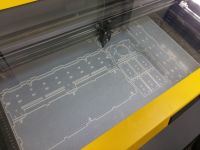
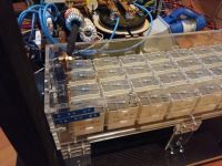
- made a new MMC (0.34 uF 16 kV DC)
- debugged UD2.7 - TL3116 was soldered backwards, thankfully nothing burned out
- phased the GDT, had to add a few turns based on loneoceans scope shots
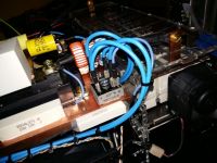
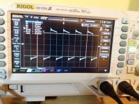
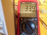
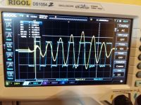
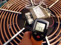
I scoped the primary current and the C1 E1 voltage, first on 30 V bus, then increased to max. 340 V (MOT as dummy load)
I didn't measure the ON-time, but I lowered it until it didn't trigger the OCD (~400 A)
Max. C1 E1 voltage is ~160 V measured by osciloscope (using Vmax option) at ~340 Apk - I didn't even touch the variable inductor on the driver
If I increase OCD ~500 A Vmax rises to 260 V at 340 V bus
My secondary and the toroid are unfortunately at another town so I'll probably have the coil complete in the next few weeks
I hope the measurements are fine
Is this looking good or am I missing something?


Re: My first DRSSTC
nzoomed, Sun Jan 29 2017, 10:41PM
They do look a very good capacitor indeed, and way cheaper than the 942C caps that nearly cost me $400 (NZD)
I am interested if these are easily available, as he is the only seller on ebay with them.
nzoomed, Sun Jan 29 2017, 10:41PM
futurist wrote ...
I have ordered these for the new MMC

It's cheaper than another 12 of 942C caps, and per datasheet 8 caps in series and 4 strings in parallel will give 0.34 uF at 16 kV DC (5.6 kV AC) with Irms = 100 A, which is even better than 942C caps so I hope they'll turn out fine
Since I'll probably receive them before I have a scope available I probably won't try the coil with the 942C caps. I'll keep them for some future project.
I have ordered these for the new MMC

It's cheaper than another 12 of 942C caps, and per datasheet 8 caps in series and 4 strings in parallel will give 0.34 uF at 16 kV DC (5.6 kV AC) with Irms = 100 A, which is even better than 942C caps so I hope they'll turn out fine
Since I'll probably receive them before I have a scope available I probably won't try the coil with the 942C caps. I'll keep them for some future project.
They do look a very good capacitor indeed, and way cheaper than the 942C caps that nearly cost me $400 (NZD)
I am interested if these are easily available, as he is the only seller on ebay with them.
Re: My first DRSSTC
Hydron, Mon Jan 30 2017, 10:38AM
Looks great, judging by the scope shots the switching is nice and clean and you've done a good job. I'd say it's ready for first light!
Hydron, Mon Jan 30 2017, 10:38AM
Looks great, judging by the scope shots the switching is nice and clean and you've done a good job. I'd say it's ready for first light!
Re: My first DRSSTC
zzz_julian_zzz, Tue Jan 31 2017, 03:34AM
one quick note:
those screws - used as primary coil fastener, MAY cause arcs.. possibly..
zzz_julian_zzz, Tue Jan 31 2017, 03:34AM
one quick note:
those screws - used as primary coil fastener, MAY cause arcs.. possibly..
Re: My first DRSSTC
futurist, Tue Jan 31 2017, 09:42AM
Yeah I'm not too happy with the primary..
Next time I'll have to figure out some better way of making primary supports
@nzoomed I've been searching a little and it appears that many people use exactly those capacitors
Like here
 ,
,
he uses them in his almost every Tesla coil
They are even more expensive than 942Cs on mouser, I'm waiting for sellers response if he still has some left
futurist, Tue Jan 31 2017, 09:42AM
Yeah I'm not too happy with the primary..
Next time I'll have to figure out some better way of making primary supports
@nzoomed I've been searching a little and it appears that many people use exactly those capacitors
Like here
 ,
,he uses them in his almost every Tesla coil
They are even more expensive than 942Cs on mouser, I'm waiting for sellers response if he still has some left
Re: My first DRSSTC
Conundrum, Tue Jan 31 2017, 10:51AM
3D printer maybe?
Conundrum, Tue Jan 31 2017, 10:51AM
3D printer maybe?
Re: My first DRSSTC
futurist, Tue Jan 31 2017, 10:58AM
OK but how to mount them?
EDIT:
I managed to get the coil working at about 500 Apk OCD, thanks to Hydron for some tips on IRC

I had some problems with the precharge relay after removing 2:1 step-down transformer (powering from 240 V AC)
The relay board jammed the arduino from booting and then some traces blew up

Relays
I disabled the precharger and I'll try to figure out what happened when I receive a new board
Increasing on-time makes almost 2 m streamers but trips the OCD, I'll try detuning the coil a bit more
How much can I push the CM200DY-24NF?
It took me a whole afternoon to get the MIDI interrupter working, so anyone using the code from oneTesla;
to run directly from USB I did the following (tested on Debian but should work on win):
in oneTesla source change MIDI boud rate to 38400
install
ttymidi -s /dev/ttyUSBxxx -b 38400 &
Using aconnect connect Midi Through port to ttymidi port (to get output list: aconnect -o)
aconnect xx:xx xx:xx
To play (Midi Through port)
aplaymidi midi_file.mid -p xx:xx
futurist, Tue Jan 31 2017, 10:58AM
OK but how to mount them?
EDIT:
I managed to get the coil working at about 500 Apk OCD, thanks to Hydron for some tips on IRC


I had some problems with the precharge relay after removing 2:1 step-down transformer (powering from 240 V AC)
The relay board jammed the arduino from booting and then some traces blew up

Relays

I disabled the precharger and I'll try to figure out what happened when I receive a new board
Increasing on-time makes almost 2 m streamers but trips the OCD, I'll try detuning the coil a bit more
How much can I push the CM200DY-24NF?
It took me a whole afternoon to get the MIDI interrupter working, so anyone using the code from oneTesla;
to run directly from USB I did the following (tested on Debian but should work on win):
in oneTesla source change MIDI boud rate to 38400
install

ttymidi -s /dev/ttyUSBxxx -b 38400 &
Using aconnect connect Midi Through port to ttymidi port (to get output list: aconnect -o)
aconnect xx:xx xx:xx
To play (Midi Through port)
aplaymidi midi_file.mid -p xx:xx
Re: My first DRSSTC
Hydron, Tue Feb 07 2017, 09:41PM
Hydron, Tue Feb 07 2017, 09:41PM
futurist wrote ...
It took me a whole afternoon to get the MIDI interrupter working, so anyone using the code from oneTesla;
to run directly from USB I did the following (tested on Debian but should work on win):
in oneTesla source change MIDI boud rate to 38400
install
ttymidi -s /dev/ttyUSBxxx -b 38400 &
Using aconnect connect Midi Through port to ttymidi port (to get output list: aconnect -o)
aconnect xx:xx xx:xx
To play (Midi Through port)
aplaymidi midi_file.mid -p xx:xx
Thanks for the tip, I've lost my (unreliably anyway) USB->MIDI converter so will give this a go once I've got a coil running in the UK.It took me a whole afternoon to get the MIDI interrupter working, so anyone using the code from oneTesla;
to run directly from USB I did the following (tested on Debian but should work on win):
in oneTesla source change MIDI boud rate to 38400
install

ttymidi -s /dev/ttyUSBxxx -b 38400 &
Using aconnect connect Midi Through port to ttymidi port (to get output list: aconnect -o)
aconnect xx:xx xx:xx
To play (Midi Through port)
aplaymidi midi_file.mid -p xx:xx
Re: My first DRSSTC
futurist, Sat Feb 11 2017, 12:22PM
@Hydron
I managed to get it working on win, using this as midi-serial converter

and this for the loopback interface

After relay board problem I continued using the other relay as precharge, disconnecting the discharge resistor.
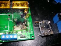
Arduino jammed again after some time and charge resistor burned out, so I finally decided to take a closer look at the relay board.
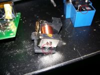
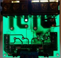
I failed to desolder relays so I ended up breaking them off the PCB. I found that the common pin of the relay is connected to the actuator
which has a short lead going exactly between the coil leads. That lead is sharp and is touching 24 V trace. So when
the soldermask gave out, 240 V AC was connected to 24 V trace - I don't know how the power supply and UD survived.
I ordered another relay board but I won't be using it for sure, it's dangerously bad!
futurist, Sat Feb 11 2017, 12:22PM
@Hydron
I managed to get it working on win, using this as midi-serial converter

and this for the loopback interface

After relay board problem I continued using the other relay as precharge, disconnecting the discharge resistor.
Arduino jammed again after some time and charge resistor burned out, so I finally decided to take a closer look at the relay board.
I failed to desolder relays so I ended up breaking them off the PCB. I found that the common pin of the relay is connected to the actuator
which has a short lead going exactly between the coil leads. That lead is sharp and is touching 24 V trace. So when
the soldermask gave out, 240 V AC was connected to 24 V trace - I don't know how the power supply and UD survived.
I ordered another relay board but I won't be using it for sure, it's dangerously bad!


Print this page
