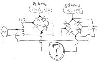
Class C tube oscillator negative rail question
thresh, Fri Dec 23 2016, 12:22AMHi guys. Please check the diagram. This is the plate and screen supply for a class C tube oscillator. I just want to make sure that I can just tie together the two -'ve rails in the diagram. The 4 * Vac * sqrt(2) goes to the plate of my tube. and the bridge rectified AC with a filter cap goes to my screen. can I just tie the two negative rails together directly, or do i need some sort of (diode? cap?) blocking. Oh, and given my drawing skills, i omitted bleeder resistors and AC shunting caps across the electrolytics indicated.
Hope this is adequate info to get a lil help from the pros here.

Re: Class C tube oscillator negative rail question
Proud Mary, Fri Dec 23 2016, 01:17PM
It would help if you actually put up a complete circuit diagram of the oscillator together with the valve type - then we could determine how its power supply requirements should best be met.
Proud Mary, Fri Dec 23 2016, 01:17PM
It would help if you actually put up a complete circuit diagram of the oscillator together with the valve type - then we could determine how its power supply requirements should best be met.

Re: Class C tube oscillator negative rail question
thresh, Sat Dec 24 2016, 03:13AM
Sorry, the circuit changes almost every time I play with this thing. As of now, this is part of an audio-modulated (via cathode modulation using an IRF630N) mini plasma tweeter using a 6KG6. Power supply as shown above plus:
A) 2.5K resistor in series / 22uF filtering in parallel with screen supply
B) 40mm diameter, .5mm wire for a 40 turns inductor to the plate
C) 25mm diameter, .5 wire for 130ish turns resonator, oscillating in the low MHz range.
D) Feedback from a loop of metal ----> 2.2nF ---> control screen / 300k resistor to ground.
And the whole thing littered with lil RF caps to protect everything
Here is 3-4 design iterations ago (it worked fine, but I always wanna fix what aint broke, and light my cigarettes off of it). The music is (duh) coming from the discharge.

Re: Class C tube oscillator negative rail question
Proud Mary, Sat Dec 24 2016, 09:48AM
I can't really comment on something that doesn't have a circuit diagram, except to say that the design of valve oscillators requires strict attention to mechanical and thermal stability, the use of high quality parts such as ceramic valve holders, effective shielding and screening to reduce electromagnetic compatibility issues, and with power oscillators, effective measures against parasitic oscillation and radiation of harmonics.
Good luck with it all! :)
Re: Class C tube oscillator negative rail question
thresh, Sat Dec 24 2016, 01:19PM
*Shrug. At these levels I've been able to run it multiple hours without redplate or redscreening, and have had zero malfunctions on audio sourced despite directly plugging in many a smartphone to it. I will draw up a diagram today. My longterm goal for this modulated power oscillator is to switch to plate modulation using the entire 0V to max ratings span from silent to full output.
In the video, you can see a black cable coming in from left screen with what looks like a disordered clump of electronic components. In reality, the entire cathode modulator circuit is built onto the audio cable itself.. only needs one to attach MOSFET drain to cathode, source to -ve rail.
Print this page