
Pulse Skipped DRSSTC Waveform
zzz_julian_zzz, Fri Sept 30 2016, 02:42PMHi Guys,
Any idea what would UD3 (with pulse skipping) logic would be like? This control feature is shown on Philip's Skinny coil - I am trying to replicate it with purely analog circuitry like in UD2 (i.e., without uControllers/ Expensive Intelligent Chips) for the reasons that I am not well versed on those chips and not have enough resource to carry on..
however, I have attempted to replicate it (pic below) and will be glad to hear your comments if it is somehow "getting to the ballpark" or my thinking of pulse skipping method is different from Steve W's...
i.e. using OCD to detect OC event then zeroed the next pulse (of both legs of inverter) and let current flow and subside thru diodes.. while switching is IN-Sync with the coil oscillation/no hard switch; then let the pulse come again 'til the next OC event... in that way that the IGBT will be helped by its copack diode in terms of energy handling..
Below is the Primary Current waveform, any ideas on the subject is highly appreciated.
Thanks in advance!

Re: Pulse Skipped DRSSTC Waveform
Hydron, Fri Sept 30 2016, 03:59PM
I sketched up a UD2.x addition for Kizmo to do exactly this.
I don't have the diagrams handy, hopefully he has saved them somewhere!
From what I recall it is quite easy to do, only one or two extra logic chips.
My solution was to turn off only one leg of the inverter, letting the current free-wheel via one co-pack diode (off-leg) and one IGBT (on-leg). This method rings down slower than when turning off both legs, which forces the current to flow back into the DC bus capacitor.
Re: Pulse Skipped DRSSTC Waveform
zzz_julian_zzz, Sat Oct 01 2016, 02:43PM
Hydron,
thanks for the useful inputs- for 1 leg off of the inverter, waveform will look like in the pic below...
Here are my concerns for this waveform:
1. Unbalance loading for IGBTs (i.e., in 1st IGBT Brick(half of the full-bridge); only 1 IGBT is switching full time and the other is skipping - which is same scenario on the 2nd Brick ... that it could lead also to unbalance heating? or duty?
2. Not Symmetrical canopy (top and below) - in my pic, you can see that the bottom part of the waveform is constantly straight unlike in the TOP peaks - it is fluctuating obviously; will there be any issues on this?
My observations/questions:
1. For Slower Change in current (fluctuation); I find it that coupling plays factor- Low K~ slow dI/dt from Sims
2. Is inductance of Pri also plays role here? how about the total surge impedance? what is ideal Z?
Do you have pics or vids of your pulse skipping attempts?
once again, thanks for the input-can't find anything relatively useful from web browsing..

Re: Pulse Skipped DRSSTC Waveform
zzz_julian_zzz, Fri Nov 04 2016, 06:02AM
Hi All,
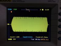
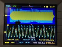
just to give an update on this thread - I was able to design a circuit that skips a certain "one pulse" every time that Primary Circuit of my DRSSTC hits a threshold which is being monitored cycle by cycle (both negative and positive going) - Skipping is done on LOW side switches only. The resultant waveform is below.
I think I am satisfied on the Current waveform (yellow on the 1st pic) as it is constantly plain on its tops and bottoms (which indicates slow dI/dt) even when skipping is happening.
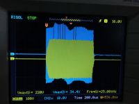
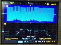
The problem I am facing right now is that because IGBTs are being driven by 2 GDTs (both of the GDTs have skipping characteristics on one of its side, which is [intended for driving LOW SIDE IGBT] and without skipping on the other side [intended for driving HIGH SIDE IGBT])--- So when skipping occurs, funny thing happens - the FLUX WALKS! {EDIT: just to clarify, 1 GDT drives 1 High side and 1 Low side IGBT}
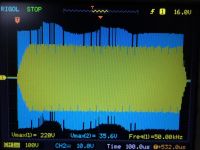
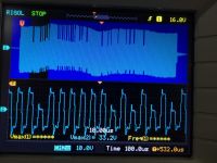
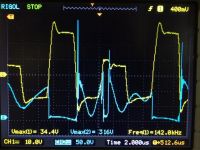
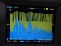
And because of this Flux walk problem – during a “skip†on a “WALK phenomena†, the gate voltages of IGBTs which are supposed to be 0 volts will be a bit higher (see pics, it is approximately ~11volts) I think this is the effect of walk, it moves the center of the waveform so it is not in 0 volts (as seen in Pics below) and causing the “supposed to be OFF IGBT†to be "ON" (for a short time) which is my concern because there will be huge current during skips and IGBT will experience hard switch (due to non-zero switching) and Voltage spikes(on my pic shots for Vge vs- Vce) and probably will cause heating/death.
I believe this flux walk is a typical response of transformer when there are unbalance drive on its primary/ which is introduced when drive skips
I have tried changing the capacitance on the GDT primary from 1 uF to 47 uF, still the FLUX WALKS
I have tried changing from 24v drive to 15v drive, still the FLUX WALKS
I have tried changing from BIG GDT core(1.5 inch to Small GDT Core(.75 inch) , still the FLUX WALKS
Pics are below – you can see there are SKIP that happens during the WALK (and so Vge greater than Zero)
With this, I would like to seek inputs from you guys on how to resolve it… My other option is just utilize OPTOCOUPLER – but as much as possible, I would like to find other solution in this and still use GDT.
Thanks in advance.
Julian


Re: Pulse Skipped DRSSTC Waveform
hen918, Fri Nov 04 2016, 10:38AM
The skipped pulse should be both positive and negative. i.e. you need to skip two pulsed one positive and one negative. Alternatively, you could alternately skip positive and negative pulses to keep the flux balance. Using an optocoupler won't help, it might just make things worse as the imbalance will be shifted from the GDT.
Re: Pulse Skipped DRSSTC Waveform
zzz_julian_zzz, Fri Nov 04 2016, 03:02PM
Hen918,
Thanks for your comment. It makes sense perfectly to me. I will revise the PCB, maybe some jumper wires will do :) I'll do the simulation on it first, but I think the name "Pulse Skip DRSSTC" should be changed to "Cycle Skip DRSSTC" because of the GDT imbalances.. Just a thought haha I have no reference on Pulse Skip Drsstc except for the Youtube Videos of Philip and that's it, So when I read "Pulse Skip" I then designed for pulse skipping circuit ...
BTW, I have made some progress on the optocoupler approach and here is the result..
My approach is get the non-skipping sides from the 2 GDTs and put it on 1 GDT - meaning this GDT do not suffer Flux Walk.. then, I put the secondaries from this non Skipping GDT to high side IGBTs and the skipping drive for the low side IGBTs are passing OPTOs (for the two AC legs). So now, I am using only 1 GDT. I also introduced some negative drive to at least mimic the GDT wave characteristics & to avoid accidental ON..
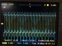
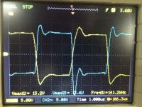
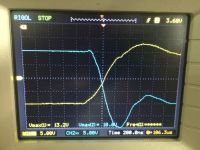
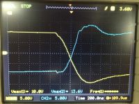
based on the pics below, I am seeing not so very bad waveforms, transition between GDT driven and opto driven are quite nice.. in the aspect of no cross conduct. Clearly there is a bit dead time on the turning on-off and off-on transitions..
BLUE - OPTOCOUPLER (driving the low side IGBT)
YELLOW - GDT (driving the high side IGBT)
another thing, have you ever tried doing Pulse Skip DRSSTC? Do you have video of it? thanks!
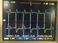
What do you think? will this work ok?
zzz_julian_zzz, Fri Nov 04 2016, 03:02PM
Hen918,
Thanks for your comment. It makes sense perfectly to me. I will revise the PCB, maybe some jumper wires will do :) I'll do the simulation on it first, but I think the name "Pulse Skip DRSSTC" should be changed to "Cycle Skip DRSSTC" because of the GDT imbalances.. Just a thought haha
 I have no reference on Pulse Skip Drsstc except for the Youtube Videos of Philip and that's it, So when I read "Pulse Skip" I then designed for pulse skipping circuit ...
BTW, I have made some progress on the optocoupler approach and here is the result..
My approach is get the non-skipping sides from the 2 GDTs and put it on 1 GDT - meaning this GDT do not suffer Flux Walk.. then, I put the secondaries from this non Skipping GDT to high side IGBTs and the skipping drive for the low side IGBTs are passing OPTOs (for the two AC legs). So now, I am using only 1 GDT. I also introduced some negative drive to at least mimic the GDT wave characteristics & to avoid accidental ON..
based on the pics below, I am seeing not so very bad waveforms, transition between GDT driven and opto driven are quite nice.. in the aspect of no cross conduct. Clearly there is a bit dead time on the turning on-off and off-on transitions..
BLUE - OPTOCOUPLER (driving the low side IGBT)
YELLOW - GDT (driving the high side IGBT)
another thing, have you ever tried doing Pulse Skip DRSSTC? Do you have video of it? thanks!


What do you think? will this work ok?
Re: Pulse Skipped DRSSTC Waveform
Hydron, Thu Nov 17 2016, 07:42AM
I sketched up my proposed way to do the pulse skipping in another thread (using 2 GDTs and skipping whole cycles to keep DC balance). Also did some simulations, let me know if you want the .asc file
Hydron, Thu Nov 17 2016, 07:42AM
I sketched up my proposed way to do the pulse skipping in another thread (using 2 GDTs and skipping whole cycles to keep DC balance). Also did some simulations, let me know if you want the .asc file
Re: Pulse Skipped DRSSTC Waveform
zzz_julian_zzz, Fri Nov 18 2016, 02:59AM
Hi Hydron,
I received ASC, thanks for that! I already plugged my coils parameter and working ok...
here's what I see the differences in our approach:
1. Yours is using both AC legs of the inverter to be skipping (both high and low side), mine is only one side (which is low side)
2. Yours (I don't know) where to put limits on current on where to trigger skip events, mine is sort of like OCD circuit
i can send you my Asc files if you want to see them too..Thanks!
Re: Pulse Skipped DRSSTC Waveform
Hydron, Fri Nov 18 2016, 09:53AM
Yeah send the Asc through, it would make it much easier to understand how you are trying to do it.
The limit in my circuit is set by H2 - the last number (500 in the schematic i emailed) is the current limit. It was done this way to simplify the simulation - we already know that the OCD circuit with comparator etc works!
Re: Pulse Skipped DRSSTC Waveform
zzz_julian_zzz, Mon Dec 05 2016, 02:31PM
Hi All,
with the help of Hydron and Phillip, I was able to apply the PSD Driver to my Coil..
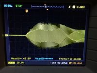
however, I am facing another problem when running on a freewheel drive...
Primary Coil tuned lower to Secondary (forcing to Lower Pole):
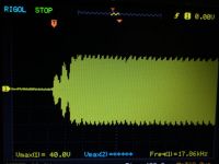
the primary current tends to be like a "sperm" shaping.. see pics below, (pic 1 &2)
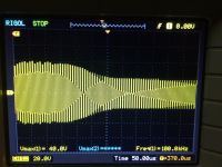
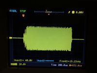
Primary Coil tuned higher to Secondary (forcing to Upper Pole)
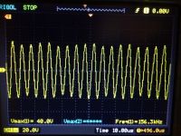
the primary current at first look, is ok since the tops and bottoms are fairly plain..
but the problem is that it experiences "notching" on the firsts few cycles - seen in the photo belows, which I believe causes the spark to be short..
Hope someone can help me on this.. Thanks!
Julian

and here is my coil spec:
-------------------------------------------- --------
Secondary Coil Inputs:
------------------------------------------ ----------
Current Profile = G.PROFILE_LOADED
2.175 = Radius 1
2.175 = Radius 2
2.51 = Height 1
13.75 = Height 2
1170 = Turns
32 = Wire Awg
--------------------------------------------- -------
Primary Coil Inputs:
------------------------------------------ ----------
Round Primary Conductor
3.25 = Radius 1
3.25 = Radius 2
1.625 = Height 1
2.5 = Height 2
5 = Turns
10 = Wire Awg
0 = Ribbon Width
0 = Ribbon Thickness
0.146667 = Primary Cap (uF)
0 = Total Lead Length
0 = Lead Diameter
---------------------------------------- ------------
Top Load Inputs:
------------------------------------------ ----------
Toroid #1: minor=4.35, major=16, height=15.75, topload
----------------------------------------- -----------
Secondary Outputs:
----------------------------------------- -----------
163.55 kHz = Secondary Resonant Frequency
90 deg° = Angle of Secondary
11.24 inch = Length of Winding
104.1 inch = Turns Per Unit
0.00166 inch = Space Between Turns (edge to edge)
1332.4 ft = Length of Wire
2.58:1 = H/D Aspect Ratio
216.8408 Ohms = DC Resistance
54523 Ohms = Reactance at Resonance
0.25 lbs = Weight of Wire
53.058 mH = Les-Effective Series Inductance
51.946 mH = Lee-Equivalent Energy Inductance
49.544 mH = Ldc-Low Frequency Inductance
17.848 pF = Ces-Effective Shunt Capacitance
18.23 pF = Cee-Equivalent Energy Capacitance
25.264 pF = Cdc-Low Frequency Capacitance
7.51 mils = Skin Depth
15.846 pF = Topload Effective Capacitance
305.4158 Ohms = Effective AC Resistance
179 = Q
----------------------------------------------- -----
Primary Outputs:
----------------------------------------- -----------
151.93 kHz = Primary Resonant Frequency
7.11 % high = Percent Detuned
90 deg° = Angle of Primary
8.51 ft = Length of Wire
8.5 mOhms = DC Resistance
0.073 inch = Average spacing between turns (edge to edge)
1.02 inch = Proximity between coils
0 inch = Recommended minimum proximity between coils
7.482 µH = Ldc-Low Frequency Inductance
0.12657 µF = Cap size needed with Primary L (reference)
0 µH = Lead Length Inductance
98.794 µH = Lm-Mutual Inductance
0.162 k = Coupling Coefficient
0.13 k = Recommended Coupling Coefficient
6.17 = Number of half cycles for energy transfer at K
19.98 µs = Time for total energy transfer (ideal quench time)
zzz_julian_zzz, Mon Dec 05 2016, 02:31PM
Hi All,
with the help of Hydron and Phillip, I was able to apply the PSD Driver to my Coil..
however, I am facing another problem when running on a freewheel drive...
Primary Coil tuned lower to Secondary (forcing to Lower Pole):
the primary current tends to be like a "sperm" shaping.. see pics below, (pic 1 &2)
Primary Coil tuned higher to Secondary (forcing to Upper Pole)
the primary current at first look, is ok since the tops and bottoms are fairly plain..
but the problem is that it experiences "notching" on the firsts few cycles - seen in the photo belows, which I believe causes the spark to be short..
Hope someone can help me on this.. Thanks!
Julian


and here is my coil spec:
-------------------------------------------- --------
Secondary Coil Inputs:
------------------------------------------ ----------
Current Profile = G.PROFILE_LOADED
2.175 = Radius 1
2.175 = Radius 2
2.51 = Height 1
13.75 = Height 2
1170 = Turns
32 = Wire Awg
--------------------------------------------- -------
Primary Coil Inputs:
------------------------------------------ ----------
Round Primary Conductor
3.25 = Radius 1
3.25 = Radius 2
1.625 = Height 1
2.5 = Height 2
5 = Turns
10 = Wire Awg
0 = Ribbon Width
0 = Ribbon Thickness
0.146667 = Primary Cap (uF)
0 = Total Lead Length
0 = Lead Diameter
---------------------------------------- ------------
Top Load Inputs:
------------------------------------------ ----------
Toroid #1: minor=4.35, major=16, height=15.75, topload
----------------------------------------- -----------
Secondary Outputs:
----------------------------------------- -----------
163.55 kHz = Secondary Resonant Frequency
90 deg° = Angle of Secondary
11.24 inch = Length of Winding
104.1 inch = Turns Per Unit
0.00166 inch = Space Between Turns (edge to edge)
1332.4 ft = Length of Wire
2.58:1 = H/D Aspect Ratio
216.8408 Ohms = DC Resistance
54523 Ohms = Reactance at Resonance
0.25 lbs = Weight of Wire
53.058 mH = Les-Effective Series Inductance
51.946 mH = Lee-Equivalent Energy Inductance
49.544 mH = Ldc-Low Frequency Inductance
17.848 pF = Ces-Effective Shunt Capacitance
18.23 pF = Cee-Equivalent Energy Capacitance
25.264 pF = Cdc-Low Frequency Capacitance
7.51 mils = Skin Depth
15.846 pF = Topload Effective Capacitance
305.4158 Ohms = Effective AC Resistance
179 = Q
----------------------------------------------- -----
Primary Outputs:
----------------------------------------- -----------
151.93 kHz = Primary Resonant Frequency
7.11 % high = Percent Detuned
90 deg° = Angle of Primary
8.51 ft = Length of Wire
8.5 mOhms = DC Resistance
0.073 inch = Average spacing between turns (edge to edge)
1.02 inch = Proximity between coils
0 inch = Recommended minimum proximity between coils
7.482 µH = Ldc-Low Frequency Inductance
0.12657 µF = Cap size needed with Primary L (reference)
0 µH = Lead Length Inductance
98.794 µH = Lm-Mutual Inductance
0.162 k = Coupling Coefficient
0.13 k = Recommended Coupling Coefficient
6.17 = Number of half cycles for energy transfer at K
19.98 µs = Time for total energy transfer (ideal quench time)
Re: Pulse Skipped DRSSTC Waveform
Chris_Dickey, Tue Dec 06 2016, 09:40PM
Hi all,
I've been playing with freewheeling since about May of last year (with Steve's UD3), and I can confirm seeing exactly what julian just posted. The main difference is that I've been achieving upper pole oscillation by means of a startup oscillator, instead of retuning. I always use upper pole operation now, because it produces bigger sparks on this coil.
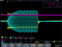
As-built, the primary alone resonates at 200kHz (with no secondary). I drive the primary at 238kHz for 6 cycles at the beginning of each burst (experimentally determined). Over the course of the burst, the primary resonant frequency drops to 200kHz and stays there. It only takes about 800us to drop to 200kHz, and I run a max of about 6ms.
I have a variety of scope captures and videos, albeit not very organized. I will do what I can to make this sensical. This did not happen in a day; I explored in several-day bursts over the course of a year, hence the different settings and scopes.
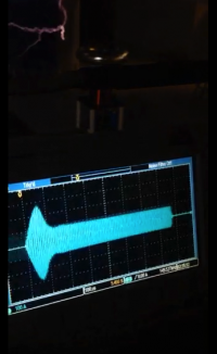
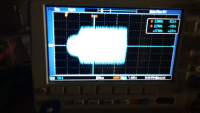
Lower pole; "mushroom" waveform:
Full video:
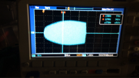
Upper pole; not full bus voltage, high current limit (never hits the limiter):
Upper pole, ground strike; same bus voltage, same limiter:
Full video:
Upper pole, higher bus voltage, higher resolution scope:
If anyone is interested in seeing how deep the rabbit hole goes, I'll organize more info about all of this.
Edit: fixed YouTube embeds
Chris_Dickey, Tue Dec 06 2016, 09:40PM
Hi all,
I've been playing with freewheeling since about May of last year (with Steve's UD3), and I can confirm seeing exactly what julian just posted. The main difference is that I've been achieving upper pole oscillation by means of a startup oscillator, instead of retuning. I always use upper pole operation now, because it produces bigger sparks on this coil.
As-built, the primary alone resonates at 200kHz (with no secondary). I drive the primary at 238kHz for 6 cycles at the beginning of each burst (experimentally determined). Over the course of the burst, the primary resonant frequency drops to 200kHz and stays there. It only takes about 800us to drop to 200kHz, and I run a max of about 6ms.
I have a variety of scope captures and videos, albeit not very organized. I will do what I can to make this sensical. This did not happen in a day; I explored in several-day bursts over the course of a year, hence the different settings and scopes.
Lower pole; "mushroom" waveform:

Full video:
Upper pole; not full bus voltage, high current limit (never hits the limiter):

Upper pole, ground strike; same bus voltage, same limiter:

Full video:
Upper pole, higher bus voltage, higher resolution scope:

If anyone is interested in seeing how deep the rabbit hole goes, I'll organize more info about all of this.
Edit: fixed YouTube embeds
Re: Pulse Skipped DRSSTC Waveform
zzz_julian_zzz, Fri Dec 30 2016, 03:41PM
Hi All,
Just to give you update on this project..

will improve it for sure :)
thanks!
Julian
zzz_julian_zzz, Fri Dec 30 2016, 03:41PM
Hi All,
Just to give you update on this project..

will improve it for sure :)
thanks!
Julian
Re: Pulse Skipped DRSSTC Waveform
zzz_julian_zzz, Thu Jan 05 2017, 02:38PM
Hi All,
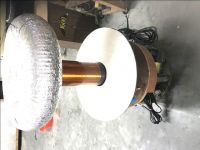
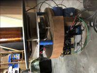
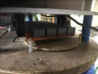
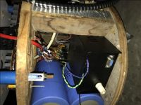
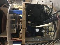
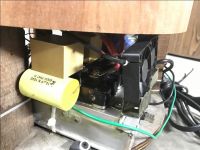
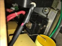
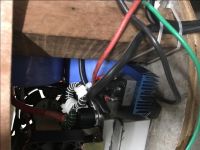
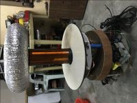
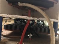
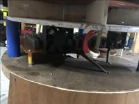
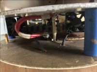
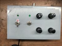
just want to show the assembly photos of this project.. My 5ft arc output goal for Pulse Skipped DRSSTC is already exceeded.. Arc now is reaching 6ft (ceiling) @4ms, 600 Amp, 35 bps ; and I believe it can go further if pulse length, OCD level, and BPS are increased but I don't want to see that anymore. That AC main wall socket in my house where I use for TC operation is only limited to 20 Amps (dedicated CB).. My Pulse Skip TC has its own 15 Ampere CB in it, and more than the above parameters and it trips..
Thanks to Hydron, Phillips and Chris for the help!
Julian


Re: Pulse Skipped DRSSTC Waveform
futurist, Tue Mar 21 2017, 03:14PM
Good work on the coil!
How did you manage to get the coil running at upper pole without using a startup oscilator?
futurist, Tue Mar 21 2017, 03:14PM
Good work on the coil!
How did you manage to get the coil running at upper pole without using a startup oscilator?
Re: Pulse Skipped DRSSTC Waveform
Hydron, Tue Mar 21 2017, 05:14PM
I suspect that he tuned the primary high enough to make the upper pole gain greater than the lower pole - as far as I know this is the only way to do it without a startup oscillator based driver.
If you have the tuning range then give it a try - it may run better or worse than at the lower pole. I ended up running my big coil at upper pole for more "controlled" sparks, especially when playing MIDI. Before I upgraded to a voltage-doubler rectifier on the mains input I ran it at lower pole for lower primary impedance and bigger sparks with the limited voltage I had to play with.
Re: Pulse Skipped DRSSTC Waveform
zzz_julian_zzz, Mon Mar 27 2017, 01:57PM
Hi Futurist,
Thanks for your interest.. first thing I just want to clarify, I am doing LOWER POLE mode of operation. It is posted/specs of the coil above... It gives the coil the thickness / intensity of sparks.. In my QCW (buck controlled), i operate in upper pole - sparks are long ~6ft and easily controlled BUT not as "intense" in terms of spark appearance vs a LOW POLE operation. In QCW -SWORD spark likeness, I needed to operate in UPPER because of control, but in my PULSE SKIP, I use lower pole simply because I want the spark to explode /express and less of containment.
My circuit (driver of my first pulse skip coil) is basically an "all analogue circuitry" nothing great in there, just a bunch of chips - reason is simplicity and because I don't know how to CLPD or FPGA
My pulse skip is doing ~5ft and I cannot go further(<4ms) due to limited power source / our house's CB is tripping and causing local brownouts. :) so I had to stop..
zzz_julian_zzz, Mon Mar 27 2017, 01:57PM
futurist wrote ...
Good work on the coil!
How did you manage to get the coil running at upper pole without using a startup oscilator?
Good work on the coil!
How did you manage to get the coil running at upper pole without using a startup oscilator?
Hi Futurist,
Thanks for your interest.. first thing I just want to clarify, I am doing LOWER POLE mode of operation. It is posted/specs of the coil above... It gives the coil the thickness / intensity of sparks.. In my QCW (buck controlled), i operate in upper pole - sparks are long ~6ft and easily controlled BUT not as "intense" in terms of spark appearance vs a LOW POLE operation. In QCW -SWORD spark likeness, I needed to operate in UPPER because of control, but in my PULSE SKIP, I use lower pole simply because I want the spark to explode /express and less of containment.
My circuit (driver of my first pulse skip coil) is basically an "all analogue circuitry" nothing great in there, just a bunch of chips - reason is simplicity and because I don't know how to CLPD or FPGA

My pulse skip is doing ~5ft and I cannot go further(<4ms) due to limited power source / our house's CB is tripping and causing local brownouts. :) so I had to stop..
Re: Pulse Skipped DRSSTC Waveform
futurist, Mon Mar 27 2017, 08:14PM
I thought that with the pulse skipping and running at lower pole the coil would detune itself so much that you couldn't get streamers that long
futurist, Mon Mar 27 2017, 08:14PM
I thought that with the pulse skipping and running at lower pole the coil would detune itself so much that you couldn't get streamers that long
Re: Pulse Skipped DRSSTC Waveform
zzz_julian_zzz, Tue Mar 28 2017, 10:23AM
Could be for some cases, but not based on what I saw from my attempt
zzz_julian_zzz, Tue Mar 28 2017, 10:23AM
futurist wrote ...
I thought that with the pulse skipping and running at lower pole the coil would detune itself so much that you couldn't get streamers that long
I thought that with the pulse skipping and running at lower pole the coil would detune itself so much that you couldn't get streamers that long
Could be for some cases, but not based on what I saw from my attempt
Re: Pulse Skipped DRSSTC Waveform
Intra, Mon Sept 11 2017, 10:07AM
Is this coil loud as QCW or as DRSSTC?
Intra, Mon Sept 11 2017, 10:07AM
zzz_julian_zzz wrote ...
Hi All,
Just to give you update on this project..

will improve it for sure :)
thanks!
Julian
Hi Julian,Hi All,
Just to give you update on this project..

will improve it for sure :)
thanks!
Julian
Is this coil loud as QCW or as DRSSTC?
Re: Pulse Skipped DRSSTC Waveform
zzz_julian_zzz, Sun Sept 17 2017, 02:25AM
Qcw is very silent type of coil..(if power source is tuned correctly - with smooth ramp down too)
Pulse Skip is different. It is a Drsstc sounding with ~50 bps or so but with more thickness in it(~4ms) so the sound is like angry drsstc.. loud and scary..
zzz_julian_zzz, Sun Sept 17 2017, 02:25AM
Intra wrote ...
Is this coil loud as QCW or as DRSSTC?
zzz_julian_zzz wrote ...
Hi All,
Just to give you update on this project..

will improve it for sure :)
thanks!
Julian
Hi Julian,Hi All,
Just to give you update on this project..

will improve it for sure :)
thanks!
Julian
Is this coil loud as QCW or as DRSSTC?
Qcw is very silent type of coil..(if power source is tuned correctly - with smooth ramp down too)
Pulse Skip is different. It is a Drsstc sounding with ~50 bps or so but with more thickness in it(~4ms) so the sound is like angry drsstc.. loud and scary..
Print this page