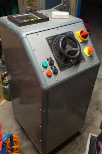
3 phase 13 A Lübcke variac with safety and monitoring
Mads Barnkob, Wed Aug 31 2016, 08:58PMSchematics, all pictures etc:

Features: start/stop, emergency stop, lockable mains switch, mains relay and circuit breaker. A PMA data monitor KS3010 to measure voltage and current on all 3 phases. The data monitor has 6 analogue input channels for signals in the range of +/- 12 VDC and samples these values as a average over 125 ms, which corresponds to 8 samples per second. Step down transformers are used for voltage measurements and CR Magnetics CR4210S-30 RMS AC current transfucers are used for the current.

SKM200 IGBT brick on top of it for size comparison :)
Re: 3 phase 13 A Lübcke variac with safety and monitoring
Patrick, Thu Sept 01 2016, 09:03AM
looks like it powers the electric chair.
Patrick, Thu Sept 01 2016, 09:03AM
looks like it powers the electric chair.
Re: 3 phase 13 A Lübcke variac with safety and monitoring
Mads Barnkob, Thu Sept 01 2016, 01:24PM
I would hope for those ending up in one that it was only a switch for full power, slowing ramping up the voltage is properly something used by various agencies in various countries. I can only hope to engage in a multi-million dollar military contract to deliver a "interrogation tool" from a time where a certain country was great, no more water boarding ;)
Mads Barnkob, Thu Sept 01 2016, 01:24PM
Patrick wrote ...
looks like it powers the electric chair.
looks like it powers the electric chair.
I would hope for those ending up in one that it was only a switch for full power, slowing ramping up the voltage is properly something used by various agencies in various countries. I can only hope to engage in a multi-million dollar military contract to deliver a "interrogation tool" from a time where a certain country was great, no more water boarding ;)
Re: 3 phase 13 A Lübcke variac with safety and monitoring
Patrick, Thu Sept 01 2016, 07:40PM
In all fairness, electric torture is more effective than water-boarding.
Patrick, Thu Sept 01 2016, 07:40PM
In all fairness, electric torture is more effective than water-boarding.
Re: 3 phase 13 A Lübcke variac with safety and monitoring
radiotech, Fri Sept 02 2016, 01:35AM
Very nice video.
Some things to consider, may be part of the circuit already. When the start button is pressed and the unit is
running, should the mains fail, when the mains restore power, will the unit start up again without the need of
again pressing the start button?
Another thing to consider, is a 'phase failure' relay or system. This will shut the unit down, or prevent starting,
until all three phases are present.
Another item, is an interlock, which could be switched in, that would require the main voltage control to be set to
zero, before the start control would work.
Re: 3 phase 13 A Lübcke variac with safety and monitoring
Mads Barnkob, Fri Sept 02 2016, 06:30AM
If you look at the schematic, you can see that start/stop buttons are pulsed, start condition is held by selfhold with the control relay, so any emergency stop, stop or mains failure will make the selfhold fall and it will have to be actively started again.
Good idea with the phase-failure detection, it could be made real simple with just 3 relays, each coil powered from a phase and their contacts put in series with the start/stop circuit. Add in 3 lamps to show which relays are energized.
I like to be able to set the variac to a voltage and then start/stop it, so I do not have to adjust for a certain voltage each time during some experiment.
I will in the future add connector for remote emergency stop and some kind of dead man switch if I find a good actuator that will release upon muscle cramp. I did not search for such yet.
Mads Barnkob, Fri Sept 02 2016, 06:30AM
radiotech wrote ...
Very nice video.
Some things to consider, may be part of the circuit already. When the start button is pressed and the unit is
running, should the mains fail, when the mains restore power, will the unit start up again without the need of
again pressing the start button?
Another thing to consider, is a 'phase failure' relay or system. This will shut the unit down, or prevent starting,
until all three phases are present.
Another item, is an interlock, which could be switched in, that would require the main voltage control to be set to
zero, before the start control would work.
If you look at the schematic, you can see that start/stop buttons are pulsed, start condition is held by selfhold with the control relay, so any emergency stop, stop or mains failure will make the selfhold fall and it will have to be actively started again.
Good idea with the phase-failure detection, it could be made real simple with just 3 relays, each coil powered from a phase and their contacts put in series with the start/stop circuit. Add in 3 lamps to show which relays are energized.
I like to be able to set the variac to a voltage and then start/stop it, so I do not have to adjust for a certain voltage each time during some experiment.
I will in the future add connector for remote emergency stop and some kind of dead man switch if I find a good actuator that will release upon muscle cramp. I did not search for such yet.
Re: 3 phase 13 A Lübcke variac with safety and monitoring
radiotech, Fri Sept 02 2016, 08:29AM
The low voltage release looks good. Sometimes our three phase
systems had a phase failure/ sequence relay shut things down, or prevented starting if the incoming lines
got reversed, ABC to ACB ,or a phase was lost.
You can make yourself a sequence indicator, easily, by Y connecting two incandescent lamps
and a capacitor. Xc = R of one of the lamps. The Y point floats.
When hooked up system, only 1 lamp will light. If you swap any two of the line
wires, the other lamp will light. If you choose an inductor instead of a capacitor, it will
work the same, except for a given sequence, the opposite lamp will light.
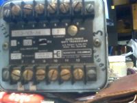
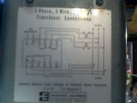
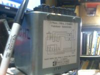
If you can find a three phase power transducer, then your total wattage can be measured.
The one shown is a Scientific Columbus 2 element 3 phase 50 Hz unit that
outputs 1.0 mA, into 0 to 10 k Ohms to indicate 875 watts.
Such old transducers lurk in industrial electrical junk heaps.
Other thing I've seen is a pot ganged along with a motor, to turn the Variac.
The pot will remember where a setting was, and the motor will turn the Variac
back to the setting, when the controller calls for a certain set point.
Depending on the experiment, you may want a PID control loop to adjust to
a certain power level. That was exactly what my watt transducer did, until our
crew revamped the whole system, using a 60 Hz type,
With a watt transducer, like the one shown below, your controller, could show kilowatts of load
on the entire system. You will need only two current transformers. If you add a var transducer
you can read kilovars.


Re: 3 phase 13 A Lübcke variac with safety and monitoring
Mads Barnkob, Fri Sept 02 2016, 11:25AM
I could take a chance with one of these cheap Chinese phase sequence relays:
I just today put up article and video about my Merlin Gerin PM700 power condition meter:
I can just plug that in front of the variac stack to have some modern commodities like harmonic distortion, power factor and power consumed measurements :)
Mads Barnkob, Fri Sept 02 2016, 11:25AM
I could take a chance with one of these cheap Chinese phase sequence relays:

I just today put up article and video about my Merlin Gerin PM700 power condition meter:

I can just plug that in front of the variac stack to have some modern commodities like harmonic distortion, power factor and power consumed measurements :)
Re: 3 phase 13 A Lübcke variac with safety and monitoring
radiotech, Fri Sept 02 2016, 02:03PM
The phase sequence relay is interesting for that amount of money. It would need some good
stickers, if was to used on a passenger elevator here .
It would be interesting to see how the power condition meter reported unbalanced loads, with
different reactive loading on each phase. Around here I have some large power factor
correction capacitors to play with. Can the condition meter connect to a computer for remote
operation, or custom programming over R 232 link ?
Re: 3 phase 13 A Lübcke variac with safety and monitoring
Bored Chemist, Sat Sept 03 2016, 02:18PM
Neither works.
Bored Chemist, Sat Sept 03 2016, 02:18PM
Patrick wrote ...
In all fairness, electric torture is more effective than water-boarding.
No it is not.In all fairness, electric torture is more effective than water-boarding.
Neither works.
Print this page