
1 kHz Modulation of a 50 kV power supply
Physikfan, Thu Jul 28 2016, 05:19PMHi
Here are first results of measurements of the modulation of the high voltage output of a 50 kV power supply.
The DC supply voltage for the high voltage power supply is 12.7 V, the modulation frequencies as well as the modulation input voltages are 500 Hz (5 Vss), 1 kHz (5 Vss), and 5 kHz (3 Vss).
The equipment: TEK 6015A, TEK 7854 with 7A26, Y1: 1V/cm, Y2: 5 kV/cm.
The zero line of the high voltage (5kV/cm) is at the bottom of the screen,
the zero line of the modulation voltage (1V/cm) is in the center of the screen.
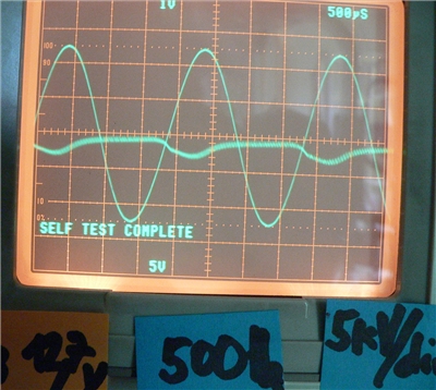
Modulation frequency is 500 Hz, modulation input voltage is 5 Vss, the high voltage is around 18 kV, the modulation amplitude is about 5 kVss.
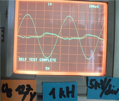
Modulation frequency is 1 kHz, modulation input voltage is 5 Vss, the high voltage is around 20 kV, the modulation amplitude is about 5 kVss.
modulation frequency is 5 kHz, modulation input voltage is 3 Vss, the high voltage is around 30 kV, the modulation amplitude is about 5 kVss
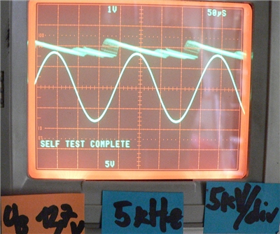
At 5 kHz the high voltage amplitude increases up to 30 kV, although the DC supply voltage is still 12.7 V, and the modulation input voltage is only 3 Vss.
I am wondering how to increase the modulation depth.
Please, has somebody some advice to solve this problem?
Regards
Physikfan
Re: 1 kHz Modulation of a 50 kV power supply
Patrick, Thu Jul 28 2016, 06:57PM
whats generating the 50 kV ?
Patrick, Thu Jul 28 2016, 06:57PM
whats generating the 50 kV ?
Re: 1 kHz Modulation of a 50 kV power supply
Physikfan, Fri Jul 29 2016, 04:02PM
Hi Patrick
Here is a picture of the power supply:
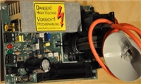
Technical data:
Input voltage: 12V - 24V DC
Input current : max . 4A
Output voltage: adjustable 0-30kVDC @ 12V and 24V @ 0-50kVDC
Output voltage is adjustable
Output current limit can be set
modulation input
Regards
Physikfan
Physikfan, Fri Jul 29 2016, 04:02PM
Hi Patrick
Here is a picture of the power supply:

Technical data:
Input voltage: 12V - 24V DC
Input current : max . 4A
Output voltage: adjustable 0-30kVDC @ 12V and 24V @ 0-50kVDC
Output voltage is adjustable
Output current limit can be set
modulation input
Regards
Physikfan
Re: 1 kHz Modulation of a 50 kV power supply
Erlend^SE, Sat Jul 30 2016, 11:33AM
Where do you have the 50 kV supply from?
Also, it may need extra load to fall quickly in output voltage.
For plasma speakers, you want power/current modulation, not voltage modulation.
Erlend^SE, Sat Jul 30 2016, 11:33AM
Where do you have the 50 kV supply from?
Also, it may need extra load to fall quickly in output voltage.
For plasma speakers, you want power/current modulation, not voltage modulation.
Re: 1 kHz Modulation of a 50 kV power supply
Physikfan, Sat Jul 30 2016, 02:34PM
Hi Erlend^SE
I got this item from:

regards
Physikfan
Physikfan, Sat Jul 30 2016, 02:34PM
Hi Erlend^SE
I got this item from:

regards
Physikfan
Re: 1 kHz Modulation of a 50 kV power supply
Erlend^SE, Sat Jul 30 2016, 07:48PM
How far do you plan to go to improve the supply?
I am building my own, but on the complex side, so it's a slow project.
By the way, what chip is the supply based around?
Erlend^SE, Sat Jul 30 2016, 07:48PM
How far do you plan to go to improve the supply?
I am building my own, but on the complex side, so it's a slow project.
By the way, what chip is the supply based around?
Re: 1 kHz Modulation of a 50 kV power supply
Physikfan, Sun Jul 31 2016, 07:30AM
Hi Erlend^SE and Patrick
Here are first results of measurements of the modulation of the high voltage output of a 50 kV power supply with a load of 5 MOhm.
The DC supply voltage for the high voltage power supply is 12 V, the modulation frequencies as well as the modulation input voltages are 250 Hz, 500 Hz, and 1 kHz (6 Vss).
The equipment: TEK 6015A, TEK 7854 with 7A26, Y1: 2 V/cm, Y2: 2 kV/cm.
The zero line of the high voltage (2 kV/cm) is at the bottom of the screen,
the zero line of the modulation voltage (2 V/cm) is in the center of the screen.
First picture:
No modulation, supply voltage is 12 V, input current is 1,25 A, load is 5 Mohm, the high voltage is around 6 kV. In addtion the oscillation amplitude from the switching frequency at 20 kHz is about 2 kVss.
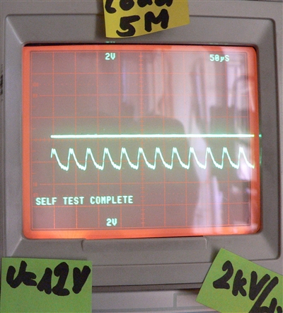
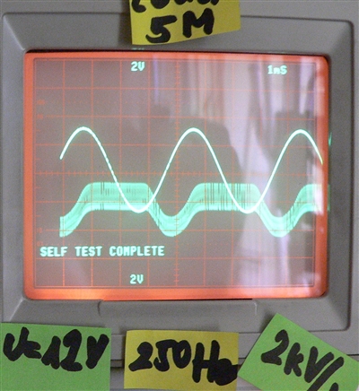
Second picture:
Modulation frequency is 250 Hz, modulation input voltage is 6 Vss, DC supply voltage is 12 V, input current is 1,0 A, load is 5 Mohm, the high voltage is around 7 kV, the high voltage modulation amplitude is 2 kVss.
In addtion the oscillation amplitude from the switching frequency at 20 kHz is about 2 kVss.
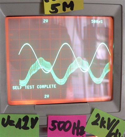
Third picture:
Modulation frequency is 500 Hz, modulation input voltage is 6 Vss, DC supply voltage is 12 V, input current is 0,95 A, load is 5 Mohm, the high voltage is around 5 kV, the high voltage modulation amplitude is 3 kVss.
In addtion the oscillation amplitude from the switching frequency at 20 kHz is about 2 kVss.
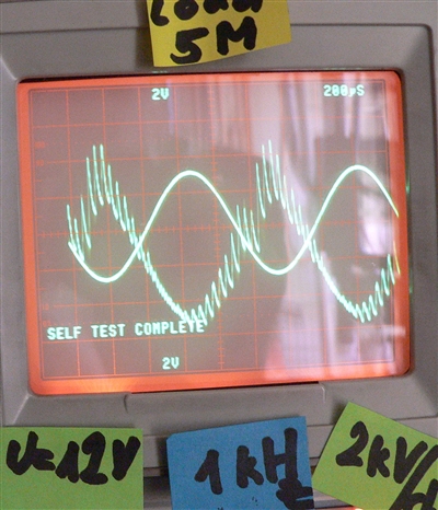
Fourth picture:
Modulation frequency is 1 kHz, modulation input voltage is 6 Vss, DC supply voltage is 12 V, input current is 1,7 A, load is 5 Mohm, the high voltage is around 11 kVss, the high voltage modulation amplitude is about 8 kVss.
In addtion the oscillation amplitude from the switching frequency at 20 kHz is up to 3 kVss.
I am looking forward to your comments.
Regards
Physikfan
Physikfan, Sun Jul 31 2016, 07:30AM
Hi Erlend^SE and Patrick
Here are first results of measurements of the modulation of the high voltage output of a 50 kV power supply with a load of 5 MOhm.
The DC supply voltage for the high voltage power supply is 12 V, the modulation frequencies as well as the modulation input voltages are 250 Hz, 500 Hz, and 1 kHz (6 Vss).
The equipment: TEK 6015A, TEK 7854 with 7A26, Y1: 2 V/cm, Y2: 2 kV/cm.
The zero line of the high voltage (2 kV/cm) is at the bottom of the screen,
the zero line of the modulation voltage (2 V/cm) is in the center of the screen.
First picture:
No modulation, supply voltage is 12 V, input current is 1,25 A, load is 5 Mohm, the high voltage is around 6 kV. In addtion the oscillation amplitude from the switching frequency at 20 kHz is about 2 kVss.

Second picture:
Modulation frequency is 250 Hz, modulation input voltage is 6 Vss, DC supply voltage is 12 V, input current is 1,0 A, load is 5 Mohm, the high voltage is around 7 kV, the high voltage modulation amplitude is 2 kVss.
In addtion the oscillation amplitude from the switching frequency at 20 kHz is about 2 kVss.

Third picture:
Modulation frequency is 500 Hz, modulation input voltage is 6 Vss, DC supply voltage is 12 V, input current is 0,95 A, load is 5 Mohm, the high voltage is around 5 kV, the high voltage modulation amplitude is 3 kVss.
In addtion the oscillation amplitude from the switching frequency at 20 kHz is about 2 kVss.

Fourth picture:
Modulation frequency is 1 kHz, modulation input voltage is 6 Vss, DC supply voltage is 12 V, input current is 1,7 A, load is 5 Mohm, the high voltage is around 11 kVss, the high voltage modulation amplitude is about 8 kVss.
In addtion the oscillation amplitude from the switching frequency at 20 kHz is up to 3 kVss.

I am looking forward to your comments.
Regards
Physikfan
Re: 1 kHz Modulation of a 50 kV power supply
Physikfan, Sun Jul 31 2016, 07:49AM
Hi Erlend^SE
Regarding your questions
"How far do you plan to go to improve the supply?"
and
"By the way, what chip is the supply based around?"
I will answer in the evening.
Regards
Physikfan
Physikfan, Sun Jul 31 2016, 07:49AM
Hi Erlend^SE
Regarding your questions
"How far do you plan to go to improve the supply?"
and
"By the way, what chip is the supply based around?"
I will answer in the evening.
Regards
Physikfan
Re: 1 kHz Modulation of a 50 kV power supply
Physikfan, Mon Aug 01 2016, 11:24AM
Hi Erlend^SE
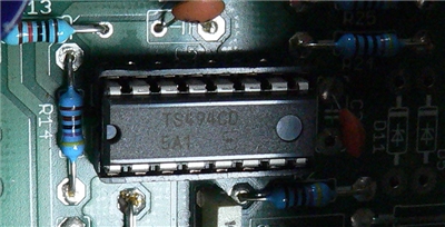
The chip of the 50 kV power supply is at the following picture.
My plans to improve this circuit are:
1. short term improvement is to create a filter consisting of coils and capacitors to suppress the 20 kHz switching signal
2. long term improvement is to add a feed back loop also to supress the 20 kHz switching signal
But the very next important step will be to increase the voltage range of an AC HV-probe at lest up to 80 or 100 kV.
I will try
1. a combination of an existing TEX P6015 and a high voltage resistor to build a voltage divider 2:1 or 3:1
2. a combination of an existing TEX P6015 and a series of capacitors also to build a voltage divider
Regards
Physikfan
Physikfan, Mon Aug 01 2016, 11:24AM
Hi Erlend^SE
The chip of the 50 kV power supply is at the following picture.

My plans to improve this circuit are:
1. short term improvement is to create a filter consisting of coils and capacitors to suppress the 20 kHz switching signal
2. long term improvement is to add a feed back loop also to supress the 20 kHz switching signal
But the very next important step will be to increase the voltage range of an AC HV-probe at lest up to 80 or 100 kV.
I will try
1. a combination of an existing TEX P6015 and a high voltage resistor to build a voltage divider 2:1 or 3:1
2. a combination of an existing TEX P6015 and a series of capacitors also to build a voltage divider
Regards
Physikfan
Re: 1 kHz Modulation of a 50 kV power supply
Physikfan, Mon Aug 01 2016, 11:40AM
Hi Erlend^SE and Patrick
Here are first results of measurements of the modulation of the high voltage output of a 50 kV power supply with a load of 10 MOhm.
The DC supply voltage for the high voltage power supply is 12 V, the modulation frequencies as well as the modulation input voltages are 250 Hz, 500 Hz, and 1 kHz (6 Vss).
The equipment: TEK 6015A, TEK 7854 with 7A26, Y1: 2 V/cm, Y2: 2 kV/cm.
The zero line of the high voltage (2 kV/cm) is at the bottom of the screen,
the zero line of the modulation voltage (2 V/cm) is in the center of the screen.
First picture:
No modulation, supply voltage is 12 V, input current is 1,25 A, load is 10 Mohm, the high voltage is around 10 kV. In addtion the oscillation amplitude from the switching frequency at 20 kHz is about 2 kVss.
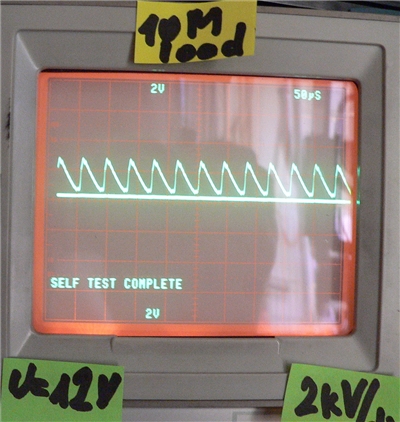
Second picture:
Modulation frequency is 250 Hz, modulation input voltage is 6 Vss, DC supply voltage is 12 V, input current is 1,0 A, load is 10 Mohm, the high voltage is around 10 kV, the high voltage modulation amplitude is 4 kVss.
In addtion the oscillation amplitude from the switching frequency at 20 kHz is about 2 kVss.
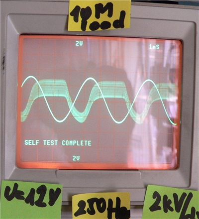
Third picture:
Modulation frequency is 500 Hz, modulation input voltage is 6 Vss, DC supply voltage is 12 V, input current is 0,95 A, load is 10 Mohm, the high voltage is around 10 kV, the high voltage modulation amplitude is 4 kVss.
In addtion the oscillation amplitude from the switching frequency at 20 kHz is about 2 kVss.
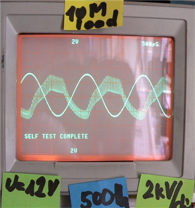
Fourth picture:
Modulation frequency is 1 kHz, modulation input voltage is 6 Vss, DC supply voltage is 12 V, input current is 1,7 A, load is 10 Mohm, the high voltage is around 14 kVss, the high voltage modulation amplitude is about 8 kVss.
In addtion the oscillation amplitude from the switching frequency at 20 kHz is up to 3 kVss.
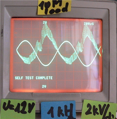
I am looking forward to your comments.
Regards
Physikfan
Physikfan, Mon Aug 01 2016, 11:40AM
Hi Erlend^SE and Patrick
Here are first results of measurements of the modulation of the high voltage output of a 50 kV power supply with a load of 10 MOhm.
The DC supply voltage for the high voltage power supply is 12 V, the modulation frequencies as well as the modulation input voltages are 250 Hz, 500 Hz, and 1 kHz (6 Vss).
The equipment: TEK 6015A, TEK 7854 with 7A26, Y1: 2 V/cm, Y2: 2 kV/cm.
The zero line of the high voltage (2 kV/cm) is at the bottom of the screen,
the zero line of the modulation voltage (2 V/cm) is in the center of the screen.
First picture:
No modulation, supply voltage is 12 V, input current is 1,25 A, load is 10 Mohm, the high voltage is around 10 kV. In addtion the oscillation amplitude from the switching frequency at 20 kHz is about 2 kVss.

Second picture:
Modulation frequency is 250 Hz, modulation input voltage is 6 Vss, DC supply voltage is 12 V, input current is 1,0 A, load is 10 Mohm, the high voltage is around 10 kV, the high voltage modulation amplitude is 4 kVss.
In addtion the oscillation amplitude from the switching frequency at 20 kHz is about 2 kVss.

Third picture:
Modulation frequency is 500 Hz, modulation input voltage is 6 Vss, DC supply voltage is 12 V, input current is 0,95 A, load is 10 Mohm, the high voltage is around 10 kV, the high voltage modulation amplitude is 4 kVss.
In addtion the oscillation amplitude from the switching frequency at 20 kHz is about 2 kVss.

Fourth picture:
Modulation frequency is 1 kHz, modulation input voltage is 6 Vss, DC supply voltage is 12 V, input current is 1,7 A, load is 10 Mohm, the high voltage is around 14 kVss, the high voltage modulation amplitude is about 8 kVss.
In addtion the oscillation amplitude from the switching frequency at 20 kHz is up to 3 kVss.

I am looking forward to your comments.
Regards
Physikfan
Re: 1 kHz Modulation of a 50 kV power supply
Erlend^SE, Mon Aug 01 2016, 04:10PM
You can't remove the switching frequency with feedback, it's a fundamental part of how the circuit works.
Still, you may get better bandwidth by tuning the feedback circuit, or make the circuit unstable and possibly self-destruct.
But you can change over some components to raise the frequency.
(that's why I asked about the controller, that seems to be a TL494 clone)
Whatever filters you add would have to be on the HV output, where all parts should ideally withstand at least 50 kV.
Input is likely good (you can meassure on the controller)
By having higher switching frequency, and some more output capacitance, you would get lower the switching noise on the output.
Capacitance lowers bandwidth, so you would have to do a trade-off.
I would suggest exploring the controller datasheet and TL494 datasheets before doing changes.
It's a key part of how it all works, and should not be ignored!
Re: 1 kHz Modulation of a 50 kV power supply
Physikfan, Mon Aug 01 2016, 09:02PM
Hi Erlend^SE
Unfortunately this generator is a commercial product and I have no electrical diagram.
Therefore I should build up a generator out my own ideas so I could control more of the really important parameters such as switching frequency etc.
Many thanks for your hints
.
My next step will be to raise the supply voltage up to 24 V and still using the load at the high voltage output.
50 kV would be to much for my P6015A but with the load the high voltage would be within the limit of 40 kV.
At least the signal of the switching frequency in the HV output is not really a great disadvantage.
Because I need this AC modulated HV power supply at the moment
only for testing the AC properties of some of my self built HV probes extending the range of 40 kV up to 80 or 100 kV.
Regards
Physikfan
Re: 1 kHz Modulation of a 50 kV power supply
Patrick, Tue Aug 02 2016, 08:53AM
Are you trying to make a CW voltage adder ? i think you said that earlier ?
Patrick, Tue Aug 02 2016, 08:53AM
Are you trying to make a CW voltage adder ? i think you said that earlier ?
Re: 1 kHz Modulation of a 50 kV power supply
Erlend^SE, Tue Aug 02 2016, 12:02PM
The datasheet for the controller actually kinda tells me how the whole circuit works.
TL494 datasheet, pag 13
This should give you a good start, if you want to figure out how the board works. It can't be very far from that.
(different topology, and different current feedback only)
I am currently doing my own high voltage supply.
Erlend^SE, Tue Aug 02 2016, 12:02PM
Physikfan wrote ...
Hi Erlend^SE
Unfortunately this generator is a commercial product and I have no electrical diagram.
Therefore I should build up a generator out my own ideas so I could control more of the really important parameters such as switching frequency etc.
Man
Hi Erlend^SE
Unfortunately this generator is a commercial product and I have no electrical diagram.
Therefore I should build up a generator out my own ideas so I could control more of the really important parameters such as switching frequency etc.
Man
The datasheet for the controller actually kinda tells me how the whole circuit works.
TL494 datasheet, pag 13
This should give you a good start, if you want to figure out how the board works. It can't be very far from that.
(different topology, and different current feedback only)
I am currently doing my own high voltage supply.
Re: 1 kHz Modulation of a 50 kV power supply
Physikfan, Tue Aug 02 2016, 03:02PM
Hi Patrick and Erlend^SE
My plans are now to extend the voltage range of TEK 6015 up to 80 kV or 100 kV to be able to measure the output voltages of IGBT driven induction coils.
Also as a part of my job I have to build up Cockcroft-Walton circuits as well as Marx generators for physics demonstration experiments.
So I really need HV voltage probes with AC features up to 100 kV ore even more.
To accomplish this I have to check the AC properties of these extended HV probe versions.
My first experiment should be to use a P6015A parallel to a second 6015 in series with another 100 MOhm resistor and to compare the curvature of the two signals.
Regards
Physikfan
Re: 1 kHz Modulation of a 50 kV power supply
Patrick, Tue Aug 02 2016, 05:28PM
i think this will be a disaster. i think youll just need a resistor ladder that goes up from ground to your highest capacitor. other wise this is going to lead to expensive long and bogus signal response.
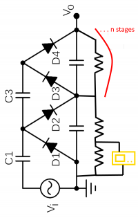
the orange part is the 0-scope, you just keep adding stages to get to your voltage. then choose resistor values high enough as to not drag down your desired output current.
Patrick, Tue Aug 02 2016, 05:28PM
Physikfan wrote ...
My first experiment should be to use a P6015A parallel to a second 6015 in series with another 100 MOhm resistor and to compare the curvature of the two signals.
My first experiment should be to use a P6015A parallel to a second 6015 in series with another 100 MOhm resistor and to compare the curvature of the two signals.
i think this will be a disaster. i think youll just need a resistor ladder that goes up from ground to your highest capacitor. other wise this is going to lead to expensive long and bogus signal response.

the orange part is the 0-scope, you just keep adding stages to get to your voltage. then choose resistor values high enough as to not drag down your desired output current.
Re: 1 kHz Modulation of a 50 kV power supply
Erlend^SE, Tue Aug 02 2016, 08:39PM
Remember a matching capacitor circuit for the measurement, or the bandwidth won't be very high.
resitive divider + capacitive divider.
Your Tektronix probe use capacitive divider.
Since it's very low capacitance, you may fail to recognise the parts of it, unless you look for it.
Print this page