
Reverse engineering the ZRG toroid
Finn Hammer, Wed Jul 27 2016, 07:29PMAll,
When I saw this thread, I wanted one! The spirally toroid

But I wanted it to be dismantleable, adjustable and understandable to make, and since I was unable to figure out how do dimension the curved tubes, this is how I went about the task:
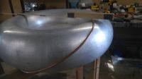
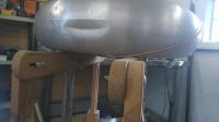
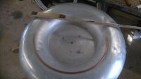
As you see, I wound a 6mm copper tube spirally around an existing toroid, and found this piece of tubing became circular, and of 2/3 of the major diameter.
With this in mind, and with a 900mm to 1100mm. toroid in mind, I started out cutting and bending tubing into 600mm diameter half circles.
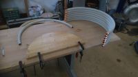
I bend the copper tubing around a half circle cut from an old shelf. And fit end caps for peace of mind.
These segments of the toroid are joined to radially mounted 15mm tubing, and this is done with the aid of solder fittings, not unlike the style seen on old iron bicycle frames.
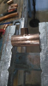
I cut them up, to get a clean outher surface, and here is a test solder, to see if it works as expected.
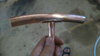
A visual BOM can be seen here
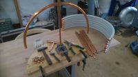
And the semifinished article can be seen here, where the structure appears more open than by the eye, perhaps I should use 12 segments instead of eight, time will tell.
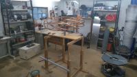
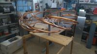
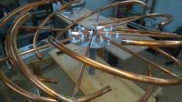
And this is a preview of what the final coil will look like
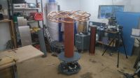
I will get back when I have measured whether the toroid delivers a capacitance corresponding to it's size, and whether it delivers proper spark holdoff properties. I may have to bend the ends of the segments to a smaller curvature, but only if I have to.
Cheers, Finn Hammer
Re: Reverse engineering the ZRG toroid
klugesmith, Thu Jul 28 2016, 08:08AM
Beautiful work, Finn. Do you and ZRG et al put anything on the tubes to preserve the shiny copper color? Or to intentionally develop and maintain an attractive patina, as with bronze art castings?

Apparently we both like to work with uncovered toes.
klugesmith, Thu Jul 28 2016, 08:08AM
Beautiful work, Finn. Do you and ZRG et al put anything on the tubes to preserve the shiny copper color? Or to intentionally develop and maintain an attractive patina, as with bronze art castings?

Apparently we both like to work with uncovered toes.

Re: Reverse engineering the ZRG toroid
zrg, Thu Jul 28 2016, 06:43PM
Actually, it's not mine, original design done by Coup de Foudre group.
In Silantor project we used bent aluminium 50mm tubes and milled plywood holders, attached to steel frame. We also crafted several smaller toploads like that (see image), but they are harder to make than regular tubing toploads used in commercial Tesla coils today, so we probably will make them only for really large coils where weight and price matter a lot.

Re: Reverse engineering the ZRG toroid
Finn Hammer, Thu Jul 28 2016, 07:17PM
Thank you for your kind words, Klugesmith. Keping copper untarnished is a bitch and not something I am going to devote my life to. Instead keep it in a plastic bag with a squirt of Ammoniumhydroxid NH4OH, and it turns green overnight.
Zerg, thanks for delving into the origin of the toroid. Yes, obviously this method is mainly usefull for big toroids. Interesting to Google Coup de Foudre...
Finn Hammer, Thu Jul 28 2016, 07:17PM
klugesmith wrote ...
Beautiful work, Finn. Do you and ZRG et al put anything on the tubes to preserve the shiny copper color? Or to intentionally develop and maintain an attractive patina, as with bronze art castings?
Beautiful work, Finn. Do you and ZRG et al put anything on the tubes to preserve the shiny copper color? Or to intentionally develop and maintain an attractive patina, as with bronze art castings?
Thank you for your kind words, Klugesmith. Keping copper untarnished is a bitch and not something I am going to devote my life to. Instead keep it in a plastic bag with a squirt of Ammoniumhydroxid NH4OH, and it turns green overnight.
zrg wrote ...
Actually, it's not mine, original design done by Coup de Foudre group.
In Silantor project we used bent aluminium 50mm tubes and milled plywood holders, attached to steel frame. We also crafted several smaller toploads like that (see image), but they are harder to make than regular tubing toploads used in commercial Tesla coils today, so we probably will make them only for really large coils where weight and price matter a lot.
Zerg, thanks for delving into the origin of the toroid. Yes, obviously this method is mainly usefull for big toroids. Interesting to Google Coup de Foudre...
Re: Reverse engineering the ZRG toroid
zrg, Thu Jul 28 2016, 07:23PM
They have two Kickstarter projects,
https://www.kickstarter.com/projects/327342610/orage-interactive-lightning-experience-at-burning/description
https://www.kickstarter.com/projects/327342610/electricus-a-tactile-experience-at-burning-man-201?ref=project_page_recs
and perhaps I've seen them either here or on Flickr.
zrg, Thu Jul 28 2016, 07:23PM
Finn Hammer wrote ...
Zerg, thanks for delving into the origin of the toroid. Yes, obviously this method is mainly usefull for big toroids. Interesting to Google Coup de Foudre...
Zerg, thanks for delving into the origin of the toroid. Yes, obviously this method is mainly usefull for big toroids. Interesting to Google Coup de Foudre...
They have two Kickstarter projects,
https://www.kickstarter.com/projects/327342610/orage-interactive-lightning-experience-at-burning/description
https://www.kickstarter.com/projects/327342610/electricus-a-tactile-experience-at-burning-man-201?ref=project_page_recs
and perhaps I've seen them either here or on Flickr.
Re: Reverse engineering the ZRG toroid
Finn Hammer, Thu Jul 28 2016, 07:58PM
All,
I punched the numbers into JavaTC and got these numbers:
The coil is 2600 turns, 940mm long on 200mm tubing, and the bare coil rings at 80khz, with a 900mm torus it rings at 45khz, increase this toroid to 1050mm, and the F.res. drops to 42khz.
These numbers were verified by driving the coil at the bottom with a function generator and sniffing the field with a dangling scope probe.
So in this respect, the toroid delivers.
Now, with regard to holding off voltage.
If the coil is driven without a breakout point, streamers are developing at the equator of the torus equally on each of the 8 segments. Tiny corona branches are developing at the ends of the tubes, and this can probably be avoided by either increasing the arc of tubing in each segment, as done by ZRG and Coup de Foudre, or by decreasing the radius of curvature on the ends of the design that I propose here.
I will do this in short order.
it is quite interesting to run the coil with up to, say, 200 mm of spark all around the torus, because every once in a while, the charge that gets stored in this corona perimeter gets discharged into just one of the streamers, which then grows to great proportions.
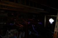
But we all poke long sticks out from our toroids, don't we? So how does this toroid behave, if you mount a suitably long discharge rod out from it? The answer is, it behaves well. If the stick protrudes just over 200mm outside the perimeter of the toroid, there is no misbehaving anywhere.
In this picture, the torus is 600mm from the ceiling, 800mm from the nearest wall and the discharge is 1100mm long.
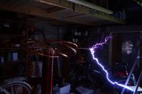
You should all take a long good look at this toroid, because in a year or two, this is what a tesla coil is going to look like.
Cheers, Finn Hammer
Finn Hammer, Thu Jul 28 2016, 07:58PM
All,
I punched the numbers into JavaTC and got these numbers:
The coil is 2600 turns, 940mm long on 200mm tubing, and the bare coil rings at 80khz, with a 900mm torus it rings at 45khz, increase this toroid to 1050mm, and the F.res. drops to 42khz.
These numbers were verified by driving the coil at the bottom with a function generator and sniffing the field with a dangling scope probe.
So in this respect, the toroid delivers.
Now, with regard to holding off voltage.
If the coil is driven without a breakout point, streamers are developing at the equator of the torus equally on each of the 8 segments. Tiny corona branches are developing at the ends of the tubes, and this can probably be avoided by either increasing the arc of tubing in each segment, as done by ZRG and Coup de Foudre, or by decreasing the radius of curvature on the ends of the design that I propose here.
I will do this in short order.
it is quite interesting to run the coil with up to, say, 200 mm of spark all around the torus, because every once in a while, the charge that gets stored in this corona perimeter gets discharged into just one of the streamers, which then grows to great proportions.

But we all poke long sticks out from our toroids, don't we? So how does this toroid behave, if you mount a suitably long discharge rod out from it? The answer is, it behaves well. If the stick protrudes just over 200mm outside the perimeter of the toroid, there is no misbehaving anywhere.
In this picture, the torus is 600mm from the ceiling, 800mm from the nearest wall and the discharge is 1100mm long.

You should all take a long good look at this toroid, because in a year or two, this is what a tesla coil is going to look like.
Cheers, Finn Hammer
Re: Reverse engineering the ZRG toroid
nzoomed, Thu Jul 28 2016, 09:57PM
My question is how do these toroids still work using bent pipes when they have no where near the same surface area as a solid toroid the same dimensions?
nzoomed, Thu Jul 28 2016, 09:57PM
My question is how do these toroids still work using bent pipes when they have no where near the same surface area as a solid toroid the same dimensions?
Re: Reverse engineering the ZRG toroid
Finn Hammer, Fri Jul 29 2016, 05:59AM
Nzoomed, all
My guess is, that the thin pipes leak charge into the air, and create a cloud of charged particles that define a surface similar to the swept surface of the pipes.
But I can hear that this explanation sounds flaky, and I hope perhaps Antonio will chip in here.
Cheers, Finn Hammer
Finn Hammer, Fri Jul 29 2016, 05:59AM
nzoomed wrote ...
My question is how do these toroids still work using bent pipes when they have no where near the same surface area as a solid toroid the same dimensions?
My question is how do these toroids still work using bent pipes when they have no where near the same surface area as a solid toroid the same dimensions?
Nzoomed, all
My guess is, that the thin pipes leak charge into the air, and create a cloud of charged particles that define a surface similar to the swept surface of the pipes.
But I can hear that this explanation sounds flaky, and I hope perhaps Antonio will chip in here.
Cheers, Finn Hammer
Re: Reverse engineering the ZRG toroid
Uspring, Fri Jul 29 2016, 09:30AM
nzoomed wrote:
Which implies what you said, i.e. the total surface area of the tubes shouldn't be too far away from the solid toroids surface area.
Uspring, Fri Jul 29 2016, 09:30AM
nzoomed wrote:
My question is how do these toroids still work using bent pipes when they have no where near the same surface area as a solid toroid the same dimensions?These toroids are similar in terms of capacitance to the more conventional ones constructed from concentric tube rings. The capacitance is close to solid toroids if the tube diameter (gauge) is not too far away from the distance between adjacent rings.
Which implies what you said, i.e. the total surface area of the tubes shouldn't be too far away from the solid toroids surface area.
Re: Reverse engineering the ZRG toroid
Antonio, Sat Jul 30 2016, 01:32AM
The "body capacitance" of a conductor depends essentially on its size, not on its area. A sphere has the largest capacitance for a given maximum diameter, but other shapes with less area are not far behind. As examples, a sphere with 1 m of diameter has 55.6 pF of capacitance, a disk 35.4 pF, a prolate spheroid with 1 m x 0.01 m (almost a straight rod) has 10.5 pF. The only problem with a toroid made with tubes is smaller breakdown voltage, but this may be not a problem when most of these coils use breakdown points to reduce it.
Re: Reverse engineering the ZRG toroid
loneoceans, Sat Aug 06 2016, 10:15PM
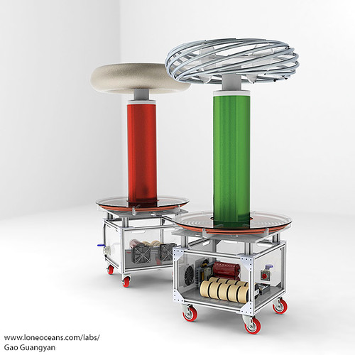
Nice job Finn. Ideally it would be nice to make it out of a single length of tubing but that's more difficult to make in practice. As you have found, using C segments is easiest and works just fine.
Here's an example coil I did a design of using the swirly toroid.
Here are the parametric eqns for you to play with:
Implicit: (R - Sqrt(x^2 + y^2))^2 + z^2 = r^2
Parametric:
x(t) = (R + rcos(qt)) cos(pt) = x (qt, pt)
y(t) = (R + rcos(qt)) sin(pt) = y (qt, pt)
z(t) = r sin(qt) = z (qt, pt)
R is the major radius, r is the minor radius, and parameters p and q define the shape of the spiral torus. Note that if p and q have a common factor, than the torus will consist of more than one 'loop'.
loneoceans, Sat Aug 06 2016, 10:15PM
Nice job Finn. Ideally it would be nice to make it out of a single length of tubing but that's more difficult to make in practice. As you have found, using C segments is easiest and works just fine.
Here's an example coil I did a design of using the swirly toroid.

Here are the parametric eqns for you to play with:
Implicit: (R - Sqrt(x^2 + y^2))^2 + z^2 = r^2
Parametric:
x(t) = (R + rcos(qt)) cos(pt) = x (qt, pt)
y(t) = (R + rcos(qt)) sin(pt) = y (qt, pt)
z(t) = r sin(qt) = z (qt, pt)
R is the major radius, r is the minor radius, and parameters p and q define the shape of the spiral torus. Note that if p and q have a common factor, than the torus will consist of more than one 'loop'.
Re: Reverse engineering the ZRG toroid
nzoomed, Tue Aug 09 2016, 10:40AM
OK thats quite interesting, i was wondering if the physics was size rather than area.
nzoomed, Tue Aug 09 2016, 10:40AM
Antonio wrote ...
The "body capacitance" of a conductor depends essentially on its size, not on its area. A sphere has the largest capacitance for a given maximum diameter, but other shapes with less area are not far behind. As examples, a sphere with 1 m of diameter has 55.6 pF of capacitance, a disk 35.4 pF, a prolate spheroid with 1 m x 0.01 m (almost a straight rod) has 10.5 pF. The only problem with a toroid made with tubes is smaller breakdown voltage, but this may be not a problem when most of these coils use breakdown points to reduce it.
The "body capacitance" of a conductor depends essentially on its size, not on its area. A sphere has the largest capacitance for a given maximum diameter, but other shapes with less area are not far behind. As examples, a sphere with 1 m of diameter has 55.6 pF of capacitance, a disk 35.4 pF, a prolate spheroid with 1 m x 0.01 m (almost a straight rod) has 10.5 pF. The only problem with a toroid made with tubes is smaller breakdown voltage, but this may be not a problem when most of these coils use breakdown points to reduce it.
OK thats quite interesting, i was wondering if the physics was size rather than area.
Print this page