
A Small QCWDRSSTC
Mr.Black, Sat Jul 23 2016, 06:53PMI built a QCWDRSSTC idea is from a few years ago, at that time saw the QCWDRSSTC STEVE WARD, shocked at such a small coil can produce such a huge arc.

Last month, have more free time, he began building QCWDRSSTC plan.
In the beginning, I needed a viable option selected.
I made reference to Gaoguangyan's UD2.7, redesigned UVLO section.
Because in China it is difficult to buy LM8385, so changed to use the LM311 comparator circuit configuration.

For the same reason, I will IFD95 DLR1150 changed to fiber optic receiver, it is often used to transmit signals of the elevator system.
Compared with HFBR2414, its anti-interference ability is poor, need to make EMC shielding measures.
Another change is the addition of an interrupt signal inverting input selection, I passed a jumper to select reverse phase interrupt signal, so that the driving circuit is adapted to BNC or twisted pair signal input.
As the modifications for UD2.7C, I put a new circuit named UD2.8A.
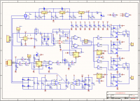
Here]qdriver2.8a.pdf[/file] PDF format schematics
I used to draw altiumDesigner10.0 the PCB, and the factory proofing.
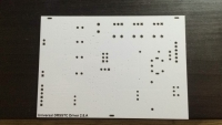
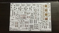
Thanks STEVE and Gaoguangyan sharing of their design so I learned a lot.

-
I use 50B60PD1 in the full bridge, and the use of four CBB22 capacitor connected in parallel bus.
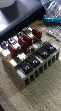
Put them together, there is the following effect.
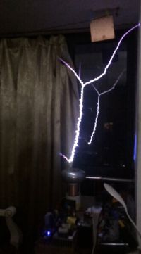
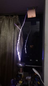
data:
The arc length of about 1.1 ~ 1.2m
BUS voltage:Ramp 10-350V
ONtime:14.5mS
OCD set:160A running in 140~150A.
Video sharing in youtube, using my Iphone5S record, unfortunately, drop-frame is still very serious.
I can get this arc feeling very happy, but I do not know why the arc is not straight,but from the same arc shape and branches fork.
I run my system at 380KHz, the longest arc frequency of 320KHz, according to the general theory, the higher the frequency, the more direct the arc, but it seems the results of my experiment is not the case.

Re: A Small QCWDRSSTC
woodchuck, Sun Jul 24 2016, 04:17AM
Looks great! Great build quality, too.
woodchuck, Sun Jul 24 2016, 04:17AM
Looks great! Great build quality, too.
Re: A Small QCWDRSSTC
Mr.Black, Sun Jul 24 2016, 05:21AM

Mr.Black, Sun Jul 24 2016, 05:21AM
woodchuck wrote ...
Looks great! Great build quality, too.
thanks! Looks great! Great build quality, too.

Re: A Small QCWDRSSTC
Mr.Black, Sun Jul 24 2016, 08:10AM
Introduce my interrupt circuit.
It uses a STM8S103K4T6 microcontroller TIM2 & TIM3 generate modulated PWM waveform, the fundamental frequency of 10.0KHz.
The offtime by TIM4 control.
Its frequency 16.0MHz reference oscillator 16 by the frequency division obtained.
So stability is very close to pure hardware circuit in actual use has been very good results.
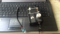
You can see in the picture on the left is using a charging cable T4056 program, which can be built-in rechargeable lithium battery, the price of this module is very cheap, just as 2.3RMB, about 0.3USD. But the function is perfect.
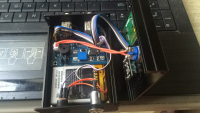
Interrupt internal structure is very simple circuit uses 4.2V cell phone lithium battery as a power source, UMT3608 module will boost battery voltage to a constant 5V. STM8 ADC in the way resources are allocated to lithium batteries, as low voltage alarm. The switch is connected to ensure that the plug-in interface when charging, disconnect the power supply circuit to prevent charging circuit with low voltage detection mutually interfering.
-
The core of the program lies in the following functions:
The code is very simple, the structure of the four parameters of the sawtooth abstraction, void Reload_Slope_Table (Slope_param_info SPF_info) function put the sawtooth waveform data into 250 points, stored in Slope_Table [250] a weft array.
In TIM2 update interrupt, load Slope_Table [250] can be achieved sawtooth modulation PWM output.
By HFBR-1414 fiber optic transmission signal to a control terminal BUCK, third-order RC low-pass filter is reduced to a sawtooth signal into the TL494 comparison.
Resulting in a full-bridge BUS change ramp waveform.
-
Thus completing the BUS modulation QCWDRSSTC
Mr.Black, Sun Jul 24 2016, 08:10AM
Introduce my interrupt circuit.
It uses a STM8S103K4T6 microcontroller TIM2 & TIM3 generate modulated PWM waveform, the fundamental frequency of 10.0KHz.
The offtime by TIM4 control.
Its frequency 16.0MHz reference oscillator 16 by the frequency division obtained.
So stability is very close to pure hardware circuit in actual use has been very good results.

You can see in the picture on the left is using a charging cable T4056 program, which can be built-in rechargeable lithium battery, the price of this module is very cheap, just as 2.3RMB, about 0.3USD. But the function is perfect.

Interrupt internal structure is very simple circuit uses 4.2V cell phone lithium battery as a power source, UMT3608 module will boost battery voltage to a constant 5V. STM8 ADC in the way resources are allocated to lithium batteries, as low voltage alarm. The switch is connected to ensure that the plug-in interface when charging, disconnect the power supply circuit to prevent charging circuit with low voltage detection mutually interfering.
-
The core of the program lies in the following functions:
typedef struct {

  uint  S_ontime;   //per100us 10-250(1ms-25ms)<*100>
  uint  S_offtime;   //pr100ms  2-50(0.2s-5s)</10>
  uint  S_top;      //top(%)10~200(5%-100%)</2>
  uint  S_scale;    //scale = rise/rise+fall time 10~190(5%-95%)</2>

}Slope_param_info;
/*global struct info*/
Slope_param_info SPARAMINFO ={100,2,200,180};
/* CUT LINE */
void Reload_Slope_Table(Slope_param_info SPF_info)
{
  static uint S_risetime,S_falltime;
  static float Ua,Fa;
    S_risetime=(uint)(SPF_info.S_ontime*SPF_info.S_scale/200);//(100uS)
    S_falltime =(uint)(SPF_info.S_ontime-S_risetime);//(100uS)
    Ua=(float)(SPF_info.S_top/S_risetime);//bit
    Fa=(float)(SPF_info.S_top/S_falltime);//bit
  for(uint i=1;i<250;i++)
    {
       if(i<S_risetime)
        {
           if((SPF_info.S_top-Slope_Table[i-1])<Ua)
            {
              Slope_Table[i]=SPF_info.S_top;
            }
           else
              Slope_Table[i]=(uint)(Slope_Table[i-1]+Ua);
        }
       if(i>=S_risetime)
        {
           if(Slope_Table[i-1]<Fa)
            {
              Slope_Table[i]=0;
              goto end_table;
            }
           else
              Slope_Table[i]=(uint)(Slope_Table[i-1]-Fa);
        }
    }
    end_table:
    return ;
}
The core of the program lies in the following functions:The code is very simple, the structure of the four parameters of the sawtooth abstraction, void Reload_Slope_Table (Slope_param_info SPF_info) function put the sawtooth waveform data into 250 points, stored in Slope_Table [250] a weft array.
In TIM2 update interrupt, load Slope_Table [250] can be achieved sawtooth modulation PWM output.
By HFBR-1414 fiber optic transmission signal to a control terminal BUCK, third-order RC low-pass filter is reduced to a sawtooth signal into the TL494 comparison.
Resulting in a full-bridge BUS change ramp waveform.
-
Thus completing the BUS modulation QCWDRSSTC

Re: A Small QCWDRSSTC
rabbit, Sun Jul 24 2016, 08:40AM
The effect can be , but why STEVE WARD circuit diagram added some useless part。。。
Also too full bridge materials
rabbit, Sun Jul 24 2016, 08:40AM
The effect can be , but why STEVE WARD circuit diagram added some useless part。。。
Also too full bridge materials
Re: A Small QCWDRSSTC
Mr.Black, Sun Jul 24 2016, 10:25AM
QCWDRSSTC running, Ontime very long. FDD8424 powered only by 2200uF filter capacitor supply.
In a short period of time, for example: 10mS, LM7824 can quickly filter capacitor to charge.
Since the GDT will consume power, so the filter capacitor is likely to decline to IGBT linear amplification area. Example 10V.
Indeed C-E of IGBT gate drive voltage and voltage drop are related, the driving voltage is too low will result in abnormal heat or fail, so the threshold is set at 18V.
Role LM311 circuit part is that when 24V bus dropped to about 18V, off interrupt signal.
Thus ensuring the drive circuit does not generate an exception.
On the other hand, the DRSSTC operation in the event of abnormal power failure, UD2.8 by 220V AC mains supply, this circuit can be quickly cut off the output GDT within a very short period of time after the power failure, rather than GDT output voltage slowly decreased from 24V to 0. BUS in parallel because the large capacitance, it may kill the IGBT.
Mr.Black, Sun Jul 24 2016, 10:25AM
rabbit wrote ...
The effect can be , but why STEVE WARD circuit diagram added some useless part。。。
Also too full bridge materials
Oh, I think I have to explain.The effect can be , but why STEVE WARD circuit diagram added some useless part。。。
Also too full bridge materials
QCWDRSSTC running, Ontime very long. FDD8424 powered only by 2200uF filter capacitor supply.
In a short period of time, for example: 10mS, LM7824 can quickly filter capacitor to charge.
Since the GDT will consume power, so the filter capacitor is likely to decline to IGBT linear amplification area. Example 10V.
Indeed C-E of IGBT gate drive voltage and voltage drop are related, the driving voltage is too low will result in abnormal heat or fail, so the threshold is set at 18V.
Role LM311 circuit part is that when 24V bus dropped to about 18V, off interrupt signal.
Thus ensuring the drive circuit does not generate an exception.
On the other hand, the DRSSTC operation in the event of abnormal power failure, UD2.8 by 220V AC mains supply, this circuit can be quickly cut off the output GDT within a very short period of time after the power failure, rather than GDT output voltage slowly decreased from 24V to 0. BUS in parallel because the large capacitance, it may kill the IGBT.

Re: A Small QCWDRSSTC
rabbit, Sun Jul 24 2016, 11:01AM
If this part of the circuit to play a role, then it shows that your power supply is not enough to drive enough power to drive IGBT. In this case, even if there is this part of the circuit, but also can not solve the problem, only to prevent the problem of your design. If the transformer is powered by a large enough power at the beginning of the design, the drive voltage will not be too low. This part of the circuit or not to play the role of.
Re: A Small QCWDRSSTC
Mr.Black, Sun Jul 24 2016, 12:58PM
May need to do is to increase the capacitance, which is a a tradeoff.
I do not think so, increase the power capacity is the best way to solve the problem. .
Another point in ud2.7c UVLO circuit design proved to be effective, you think this is a failure of the design?
A contrary view, I think the UVLO circuit design is a preventive measures.
Mr.Black, Sun Jul 24 2016, 12:58PM
rabbit wrote ...
If this part of the circuit to play a role, then it shows that your power supply is not enough to drive enough power to drive IGBT. In this case, even if there is this part of the circuit, but also can not solve the problem, only to prevent the problem of your design. If the transformer is powered by a large enough power at the beginning of the design, the drive voltage will not be too low. This part of the circuit or not to play the role of.
IGBT drivers need is a large pulse power.If this part of the circuit to play a role, then it shows that your power supply is not enough to drive enough power to drive IGBT. In this case, even if there is this part of the circuit, but also can not solve the problem, only to prevent the problem of your design. If the transformer is powered by a large enough power at the beginning of the design, the drive voltage will not be too low. This part of the circuit or not to play the role of.
May need to do is to increase the capacitance, which is a a tradeoff.
I do not think so, increase the power capacity is the best way to solve the problem. .
Another point in ud2.7c UVLO circuit design proved to be effective, you think this is a failure of the design?
A contrary view, I think the UVLO circuit design is a preventive measures.
Re: A Small QCWDRSSTC
rabbit, Sun Jul 24 2016, 05:01PM
Perhaps you are right, but I think that if the power supply part of the design is strong enough, the use of this part of the circuit will be very small
rabbit, Sun Jul 24 2016, 05:01PM
Perhaps you are right, but I think that if the power supply part of the design is strong enough, the use of this part of the circuit will be very small
Re: A Small QCWDRSSTC
zrg, Mon Jul 25 2016, 01:15PM
To properly drive a double H-bridge of 50B60 at 350-400 kHz you may need at least 24V 3A power supply, no matter the driver schematics. And yes, additional power supply capacitors may be necessary in any case.
zrg, Mon Jul 25 2016, 01:15PM
To properly drive a double H-bridge of 50B60 at 350-400 kHz you may need at least 24V 3A power supply, no matter the driver schematics. And yes, additional power supply capacitors may be necessary in any case.
Re: A Small QCWDRSSTC
zzz_julian_zzz, Tue Jul 26 2016, 11:02AM
Hi Mr. Black,
Great build! Great Coil!
Few suggestions:
1. I watched the video, and I heard squeals of the buck... do you know the freq of your PWM? It should be above 20 khz where humans cannot hear anymore. Can you increase it?
2. 350 Vdc is your ramp peak or DC before buck peak? You may want to increase effective inverter impedance
3. I use 10mf on my 24v rails with 1 amp 24v transformer.. I had no problems with it.
Re: A Small QCWDRSSTC
Mr.Black, Wed Jul 27 2016, 11:58AM

Mr.Black, Wed Jul 27 2016, 11:58AM
zrg wrote ...
To properly drive a double H-bridge of 50B60 at 350-400 kHz you may need at least 24V 3A power supply, no matter the driver schematics. And yes, additional power supply capacitors may be necessary in any case.
It may have to be replaced by SMPS, which can provide a greater power. To properly drive a double H-bridge of 50B60 at 350-400 kHz you may need at least 24V 3A power supply, no matter the driver schematics. And yes, additional power supply capacitors may be necessary in any case.

Re: A Small QCWDRSSTC
Mr.Black, Wed Jul 27 2016, 12:09PM
Thank you for your compliment
I answer these questions.
1:I used the frequency of PWM in 10KHz.So you can hear some squeals.
2:Yes.because the MMC capacity is fixed, the impedance is relatively large. 350V is the BUCK input voltage.
3.So, big 10MF capacity!. I think I should make some changes on the PCB in order to adapt to such a large package.
Mr.Black, Wed Jul 27 2016, 12:09PM
zzz_julian_zzz wrote ...
Hi Mr. Black,
Great build! Great Coil!
Few suggestions:
1. I watched the video, and I heard squeals of the buck... do you know the freq of your PWM? It should be above 20 khz where humans cannot hear anymore. Can you increase it?
2. 350 Vdc is your ramp peak or DC before buck peak? You may want to increase effective inverter impedance
3. I use 10mf on my 24v rails with 1 amp 24v transformer.. I had no problems with it.
Hi Julian Hi Mr. Black,
Great build! Great Coil!
Few suggestions:
1. I watched the video, and I heard squeals of the buck... do you know the freq of your PWM? It should be above 20 khz where humans cannot hear anymore. Can you increase it?
2. 350 Vdc is your ramp peak or DC before buck peak? You may want to increase effective inverter impedance
3. I use 10mf on my 24v rails with 1 amp 24v transformer.. I had no problems with it.
Thank you for your compliment
I answer these questions.
1:I used the frequency of PWM in 10KHz.So you can hear some squeals.
2:Yes.because the MMC capacity is fixed, the impedance is relatively large. 350V is the BUCK input voltage.
3.So, big 10MF capacity!. I think I should make some changes on the PCB in order to adapt to such a large package.

Print this page