
Build Log - Modulated SGTC
Art, Tue Mar 29 2016, 11:40AMHi Guys :)
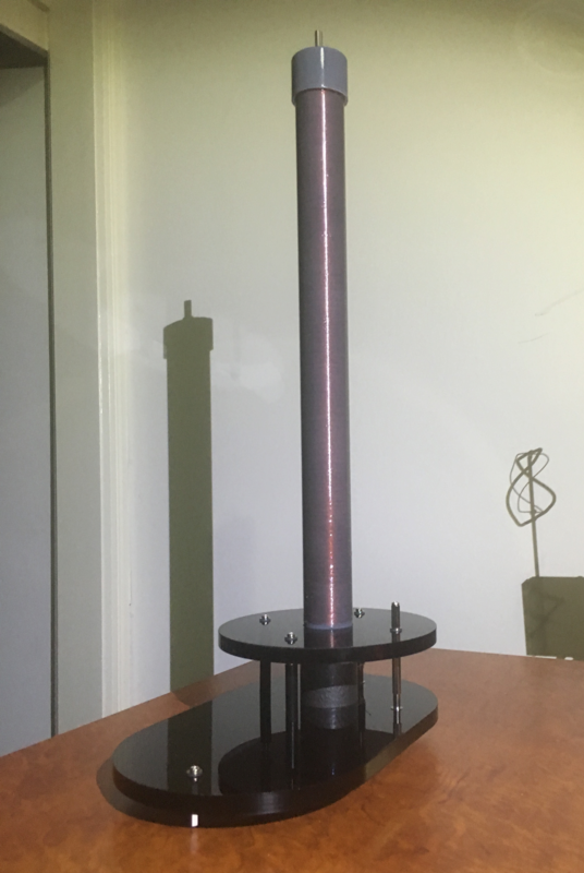
I thought I’d share as I go. This one has worked well as a mess on a table,
and now I aim to replicate that setup in a fancy finished version.
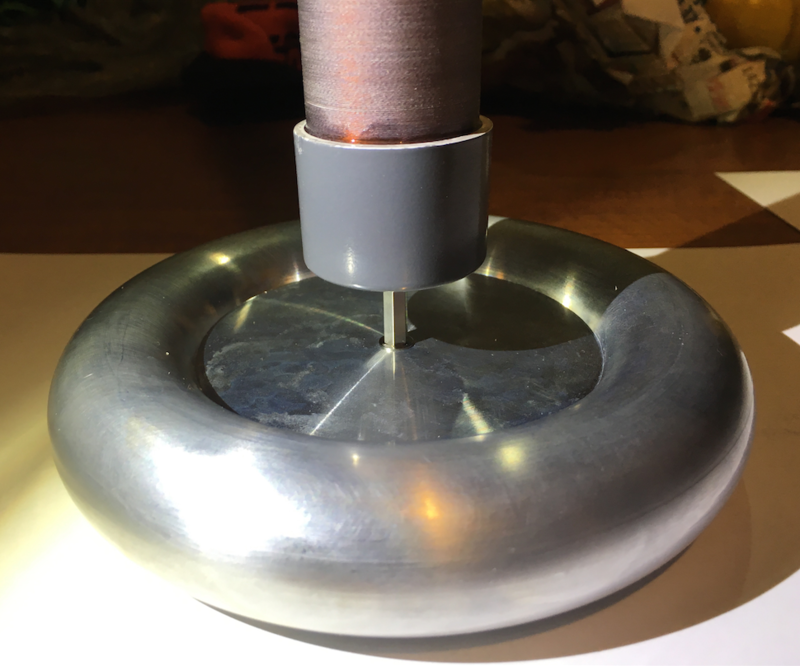
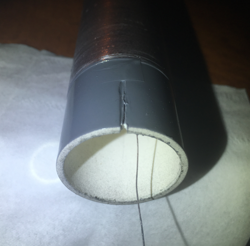
Probably the most risky part I’m proud to say is still continuous... an inner connection to the torus :D
Now with that done I’ll pot the inner of the tube with whatever I can find.
Cheers, Art.
Centre Torus Connection:
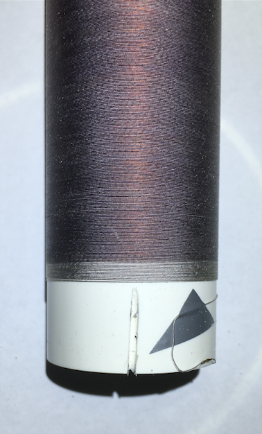
Inner Groove:
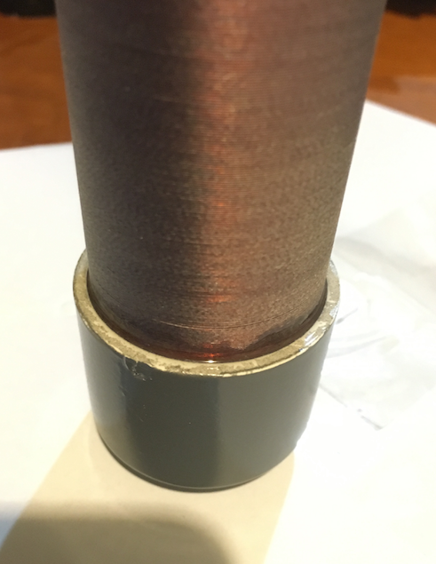
Clear Epoxy:
Re: Build Log - Modulated SGTC
Phil33ts, Sun Apr 03 2016, 11:15AM
This is nice. How did you make torus?
Can you give us the exact specification of the coil, height, wire diamater, resonant frequency, etc?
Phil33ts, Sun Apr 03 2016, 11:15AM
This is nice. How did you make torus?
Can you give us the exact specification of the coil, height, wire diamater, resonant frequency, etc?
Re: Build Log - Modulated SGTC
Mads Barnkob, Sun Apr 03 2016, 11:41AM
Could you please elaborate more on the "modulated sgtc" part of this project?
Mads Barnkob, Sun Apr 03 2016, 11:41AM
Could you please elaborate more on the "modulated sgtc" part of this project?
Re: Build Log - Modulated SGTC
Art, Sun Apr 03 2016, 11:44AM
Hi :)
I didn’t make the torus, it’s available from eBay (150mm).
The outer diameter is 34mm, and the height is 33cm.
The wire will probably never be replaced, it’s vintage enamel and cloth covered wire :D
I didn’t do any math, just wound more turns for secondary than I thought I’d need in case I wanted to unwind some.
It’s performed well as a slayer exciter and as a SGTC,
so I just aim to replicate what was on the bench, but in a nicely finished way.
A bit of progress... but now stuck waiting for parts to continue.
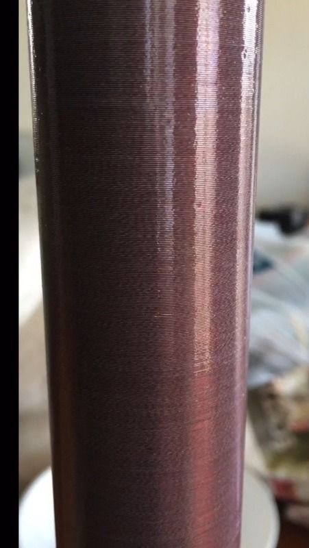
Secondary Clear Epoxy:
Teir 1 & 2:
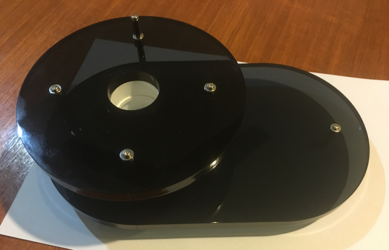
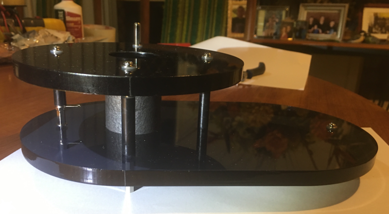
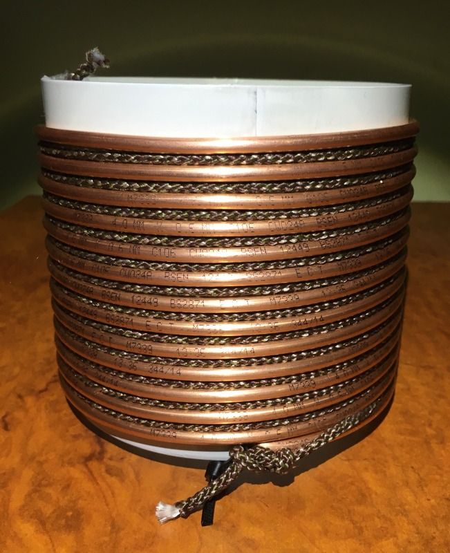
Primary Formed:
Bench Test Video:

Sorry Mads Barnkob, you must have just jumped in there as I posted.
I plan to use a DC SSR to pulse modulate the power supply to the ZVS driver.
I don’t think it would get to audio frequencies, but perhaps a visible strobe.
I got some desirable effects just touching the supply to the positive battery terminal myself at varying intervals.
Art, Sun Apr 03 2016, 11:44AM
Hi :)
I didn’t make the torus, it’s available from eBay (150mm).
The outer diameter is 34mm, and the height is 33cm.
The wire will probably never be replaced, it’s vintage enamel and cloth covered wire :D
I didn’t do any math, just wound more turns for secondary than I thought I’d need in case I wanted to unwind some.
It’s performed well as a slayer exciter and as a SGTC,
so I just aim to replicate what was on the bench, but in a nicely finished way.
A bit of progress... but now stuck waiting for parts to continue.
Secondary Clear Epoxy:


Teir 1 & 2:


Primary Formed:

Bench Test Video:

Sorry Mads Barnkob, you must have just jumped in there as I posted.
I plan to use a DC SSR to pulse modulate the power supply to the ZVS driver.
I don’t think it would get to audio frequencies, but perhaps a visible strobe.
I got some desirable effects just touching the supply to the positive battery terminal myself at varying intervals.

Re: Build Log - Modulated SGTC
Benjamin, Mon Apr 04 2016, 04:30AM
When I hear "modulated SGTC" I would think of something like a DC power supply to charge the cap bank at a high BPS rate and a MIDI triggered spark gap. I haven't seen this done before and I think that it would be pretty cool.
Benjamin, Mon Apr 04 2016, 04:30AM
When I hear "modulated SGTC" I would think of something like a DC power supply to charge the cap bank at a high BPS rate and a MIDI triggered spark gap. I haven't seen this done before and I think that it would be pretty cool.
Re: Build Log - Modulated SGTC
Sigurthr, Mon Apr 04 2016, 06:57AM
I initially assumed he was going to adjust the voltage feeding the cap, maybe with a magnetic amp or something.
Sigurthr, Mon Apr 04 2016, 06:57AM
I initially assumed he was going to adjust the voltage feeding the cap, maybe with a magnetic amp or something.
Re: Build Log - Modulated SGTC
hen918, Tue Apr 05 2016, 04:43PM
It might be easier to start / stop the oscillator/driver by pulling the gates of the MOSFETs low via a couple of diodes. Will have to try this out at some point. May be possible to turn a Mazzilli driver into a Voltage controlled power supply with pulse width modulation. It might be quite slow to react though.
Edit: I presume it's a Mazzilli and not some other ZVS driver...
Re: Build Log - Modulated SGTC
Art, Wed Apr 06 2016, 03:08AM
I hadn’t thought about disabling the driver (it is one of those cheap ZVS driver from eBay driving a flyback).
That could save a solid state relay, which would be nice :)
I would assume though, it still wouldn’t get to audio frequencies.
So far I haven’t had as much luck replicating the results achieved on the bench now that it’s partially assembled.
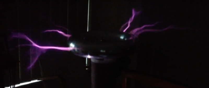
This is a typical video frame from when it was working in bits on a table.
From there, it now has a larger torus which I expect to lower the frequency and require more turns on the primary,
or a wider primary for the same capacitor array.
nmoderator edit:
Hi again Guys :D
Testing the primary LC circuit and secondary with larger torus today with an RF signal generator and scope,
I measured the secondary resonant frequency at 707kHz (without any wire simulating streamers),
and the primary LC circuit was more than 100kHz higher with all of the inductor's 13 turns used.
Adding another 1000pF capacitance (from initially 2000pF) brought the primary LC
down to about 50kHz below the secondary resonant frequency (about 650kHz).
Considering just about anything I do should lower the secondary f further,
I suppose the primary still needs to be down lower.
I just used all of the capacitors I have at the moment for the current cap array.
If the 13 turns primary was maintained, which of decreasing the coil pitch or increasing the coil diameter
would be expected to increase primary inductance further?
Art, Wed Apr 06 2016, 03:08AM
I hadn’t thought about disabling the driver (it is one of those cheap ZVS driver from eBay driving a flyback).
That could save a solid state relay, which would be nice :)
I would assume though, it still wouldn’t get to audio frequencies.
So far I haven’t had as much luck replicating the results achieved on the bench now that it’s partially assembled.
This is a typical video frame from when it was working in bits on a table.
From there, it now has a larger torus which I expect to lower the frequency and require more turns on the primary,
or a wider primary for the same capacitor array.

nmoderator edit:
Hi again Guys :D
Testing the primary LC circuit and secondary with larger torus today with an RF signal generator and scope,
I measured the secondary resonant frequency at 707kHz (without any wire simulating streamers),
and the primary LC circuit was more than 100kHz higher with all of the inductor's 13 turns used.
Adding another 1000pF capacitance (from initially 2000pF) brought the primary LC
down to about 50kHz below the secondary resonant frequency (about 650kHz).
Considering just about anything I do should lower the secondary f further,
I suppose the primary still needs to be down lower.
I just used all of the capacitors I have at the moment for the current cap array.
If the 13 turns primary was maintained, which of decreasing the coil pitch or increasing the coil diameter
would be expected to increase primary inductance further?
Re: Build Log - Modulated SGTC
dexter, Wed Apr 06 2016, 12:17PM
both :)
play around with java tc. is quite good

dexter, Wed Apr 06 2016, 12:17PM
Art wrote ...
If the 13 turns primary was maintained, which of decreasing the coil pitch or increasing the coil diameter
would be expected to increase primary inductance further?
If the 13 turns primary was maintained, which of decreasing the coil pitch or increasing the coil diameter
would be expected to increase primary inductance further?
both :)
play around with java tc. is quite good

Re: Build Log - Modulated SGTC
Art, Wed Apr 06 2016, 01:52PM
I meant which of the two is most effective to try first,
but I suppose Java TC is a practical way to find out :D
It also occurred to me that I have the next size down fancy torus as well,
and it should lower the resonant frequency of the secondary to add it to the top load.
Another thing Java TC should help with getting an idea about!
moderator edit:
Ok Guys, what gives?? :D
I have measured the secondary at 700kHz,
and the primary LC circuit at 650kHz with 13 turns,
so I should be able to lower coil turns slightly to increase
frequency of the primary circuit up to the 700kHz.
All of this measurement was done with the test unit assembled.
I tried to keep the video down to 30 seconds:

The still photo at the end is where I actually begin to get some output,
which is only about five turns with all the same setup!
Art, Wed Apr 06 2016, 01:52PM
I meant which of the two is most effective to try first,
but I suppose Java TC is a practical way to find out :D
It also occurred to me that I have the next size down fancy torus as well,
and it should lower the resonant frequency of the secondary to add it to the top load.
Another thing Java TC should help with getting an idea about!
moderator edit:
Ok Guys, what gives?? :D
I have measured the secondary at 700kHz,
and the primary LC circuit at 650kHz with 13 turns,
so I should be able to lower coil turns slightly to increase
frequency of the primary circuit up to the 700kHz.
All of this measurement was done with the test unit assembled.
I tried to keep the video down to 30 seconds:

The still photo at the end is where I actually begin to get some output,
which is only about five turns with all the same setup!
Re: Build Log - Modulated SGTC
Sigurthr, Thu Apr 07 2016, 04:46AM
Thin, long wire connections, gator clips, possibly poor ground, lots of "stuff" around the coil... all these things detune it. You've got losses and failure points stacked up pretty high. I'd try improving the physical set up and then measuring things again.
Sigurthr, Thu Apr 07 2016, 04:46AM
Thin, long wire connections, gator clips, possibly poor ground, lots of "stuff" around the coil... all these things detune it. You've got losses and failure points stacked up pretty high. I'd try improving the physical set up and then measuring things again.
Re: Build Log - Modulated SGTC
Art, Thu Apr 07 2016, 01:42PM
Hi :) It was pretty much the same setup for the primary,
except what has to be changed.
It’s the first YouTube hit for “Tesla Coil Tuning†that I followed.
It just seems to me that was a dramatic difference to use less than half the primary turns for resonance.
I have got performance back up to my initial bench testing, so that’s good :)
Re: Build Log - Modulated SGTC
Art, Sat Apr 09 2016, 05:51PM
Thinking about this today when I ran the ZVS driver a little higher voltage than it’s rated,
I felt RF on the positive battery terminal for the first time.
Maybe it’s back EMF from the flyback transformer, or maybe from the Tesla coil primary from too high voltage for the diode in the flyback.
Now I worry that connecting an IO pin from a 555 or microcontroller, will wobble it’s supply
through it’s diodes and such. If a microcontoller supply line is wobbled too much it makes it impossible to use it’s inputs.
There’s no telling the DC solid state relay will isolate the load from the silicon controlling it either,
at least until I find a data sheet on it.
I do have a test oscillator ready for it now that can strobe at visual frequencies, and then use a second 555 to
modulate the strobed signal at audio frequencies. It also has a 1A H-Bridge in case it helps to drive the DC SSR
control input with current, and then pull down (or go high impedance) to turn the SSR control input off.
Art, Sat Apr 09 2016, 05:51PM
hen918 wrote ...
It might be easier to start / stop the oscillator/driver by pulling the gates of the MOSFETs low via a couple of diodes. Will have to try this out at some point. May be possible to turn a Mazzilli driver into a Voltage controlled power supply with pulse width modulation. It might be quite slow to react though.
Edit: I presume it's a Mazzilli and not some other ZVS driver...
Thinking about this today when I ran the ZVS driver a little higher voltage than it’s rated,
I felt RF on the positive battery terminal for the first time.
Maybe it’s back EMF from the flyback transformer, or maybe from the Tesla coil primary from too high voltage for the diode in the flyback.
Now I worry that connecting an IO pin from a 555 or microcontroller, will wobble it’s supply
through it’s diodes and such. If a microcontoller supply line is wobbled too much it makes it impossible to use it’s inputs.
There’s no telling the DC solid state relay will isolate the load from the silicon controlling it either,
at least until I find a data sheet on it.
I do have a test oscillator ready for it now that can strobe at visual frequencies, and then use a second 555 to
modulate the strobed signal at audio frequencies. It also has a 1A H-Bridge in case it helps to drive the DC SSR
control input with current, and then pull down (or go high impedance) to turn the SSR control input off.
Re: Build Log - Modulated SGTC
hen918, Wed Apr 13 2016, 08:25PM
I've just built an uzzors2k style capacitor charge controller: , and when not attached to any charging capacitor, the feedback loop turns it into an interrupter in the mid audio range.
A proper modulator could be built quite well using diodes to disable the driver, I think.
hen918, Wed Apr 13 2016, 08:25PM
I've just built an uzzors2k style capacitor charge controller:
 , and when not attached to any charging capacitor, the feedback loop turns it into an interrupter in the mid audio range.
 A proper modulator could be built quite well using diodes to disable the driver, I think.
Re: Build Log - Modulated SGTC
Art, Thu Apr 14 2016, 10:20AM
Hi :) That does seem the most streamline way to go, but I’ve moved to an idea using three identical SS DC relays to
switch in the battery array at three different taps.. 12V (for tuning with a narrow gap), then 24-36V during operation
which could be sequenced by the microcontroller. Hopefully also with some frequency feedback to turn it off if it stops working.
Re: Build Log - Modulated SGTC
Art, Fri May 06 2016, 04:24PM
Hi Guys :)
This is kind of what I meant by “Modulated SGTCâ€.
It shouldn’t be possible to modulate it at a higher frequency than the spark is arcing.

It was the perfect project to try an oscilloscope with a HD44780 LCD controller.
The keypad is connected with Toslink hardware talked about in another thread.
Cheers, Art.
Art, Fri May 06 2016, 04:24PM
Hi Guys :)
This is kind of what I meant by “Modulated SGTCâ€.
It shouldn’t be possible to modulate it at a higher frequency than the spark is arcing.

It was the perfect project to try an oscilloscope with a HD44780 LCD controller.
The keypad is connected with Toslink hardware talked about in another thread.
Cheers, Art.
Re: Build Log - Modulated SGTC
Art, Sun May 22 2016, 04:49AM
That was hair raising to glue the primary form together: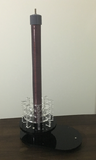
Now I have 3 DC SSRs at different voltage taps so it should actually be possible to make a very crude sine at the controller end.
Art, Sun May 22 2016, 04:49AM
That was hair raising to glue the primary form together:

Now I have 3 DC SSRs at different voltage taps so it should actually be possible to make a very crude sine at the controller end.
Re: Build Log - Modulated SGTC
Sulaiman, Sun May 22 2016, 06:53AM
Very nice !
A late answer to your question
" If the 13 turns primary was maintained,
which of decreasing the coil pitch or increasing the coil diameter
would be expected to increase primary inductance further?"
for a LONG solenoid L = u.Area.n^2/height,
so inductance is proportional to r^2
and inversely proportional to height.
for shorter coils this is not correct but similar, L = (r^2 x N^2)/((9 x r) + (10 x h))
but not quite so easy to conceptualise.
for a given length of wire or copper tubing,
maximum inductance is achieved when the radius is approximately equal to the height.
(conductor length = 2 x pi x r x n plus the above formula allows you to prove it ! )
so increasing the coil diameter will have the greatest effect, but needs more copper,
and of course coupling will decrease much more compared to shortening the primary.
"It shouldn’t be possible to modulate it at a higher frequency than the spark is arcing"
true,
but the audio modulating frequency needs to be less than half of the spark repetition frequency
to avoid severe distortion
For audio modulation you intend to use DC SSRs,
is the frequency response of your SSRs adequate ?
Sulaiman, Sun May 22 2016, 06:53AM
Very nice !
A late answer to your question
" If the 13 turns primary was maintained,
which of decreasing the coil pitch or increasing the coil diameter
would be expected to increase primary inductance further?"
for a LONG solenoid L = u.Area.n^2/height,
so inductance is proportional to r^2
and inversely proportional to height.
for shorter coils this is not correct but similar, L = (r^2 x N^2)/((9 x r) + (10 x h))
but not quite so easy to conceptualise.
for a given length of wire or copper tubing,
maximum inductance is achieved when the radius is approximately equal to the height.
(conductor length = 2 x pi x r x n plus the above formula allows you to prove it ! )
so increasing the coil diameter will have the greatest effect, but needs more copper,
and of course coupling will decrease much more compared to shortening the primary.
"It shouldn’t be possible to modulate it at a higher frequency than the spark is arcing"
true,
but the audio modulating frequency needs to be less than half of the spark repetition frequency
to avoid severe distortion

For audio modulation you intend to use DC SSRs,
is the frequency response of your SSRs adequate ?
Re: Build Log - Modulated SGTC
Art, Sun May 22 2016, 07:17AM
Hi, & Thanks :)
It’s a bit late to make changes now. I wish I’d gone a little wider,
but the problem remains I’d need a wider form to wind it.
This primary form was made so I could pre-wind the copper tube
onto a stock section of PVC, and then thread it after.
There’s more room to move with tuning than I expected though,
since my measurements with signal generator & scope weren’t consistent with the unit in operation,
and the error worked in my favour.
It’s not audio frequencies I’m hoping for right now, just strobe and pulse effects.
The spark gap operates at an audio frequency, so I can’t expect to modulate that with another audio frequency.
The DC SSRs appear to handle audio speeds at the current they’re switching though.
The whole base part including the driver stuff which is not pictured here is being built modular,
so one day it would be possible to keep the transformer, and update the rest :)
It’s taken a very long time considering I wound the secondary in October ’15!
It’s never going to impress with massive arcs, so the plan has always been to be distinguished in other ways.
Re: Build Log - Modulated SGTC
Art, Thu Jun 16 2016, 02:31PM
Hi Guys :)
Almost done this assembly, and then onto the driver enclosure part.
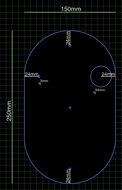
The extra part I have, but not fitted yet is an identical base acrylic piece to go under the ground plane,
so it looks like a silver band about the perimeter of the base.
The discs are made the same size as a torus larger then this (which I also have).
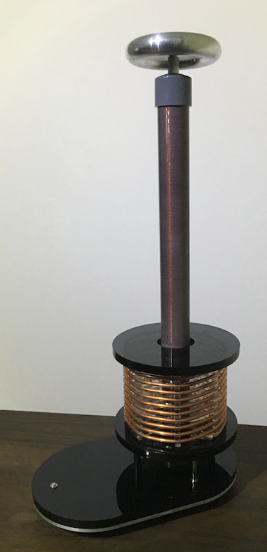
There are still two hidden conductors followed right through to the base standoffs, so only a single wire
will be seen connected from the entire driver section.. which is the wire used to adjust the primary.
Possibly there will be a need for a ceramic insulator where the bottom of the primary passes through the ground plane.
Art, Thu Jun 16 2016, 02:31PM
Hi Guys :)
Almost done this assembly, and then onto the driver enclosure part.
The extra part I have, but not fitted yet is an identical base acrylic piece to go under the ground plane,
so it looks like a silver band about the perimeter of the base.
The discs are made the same size as a torus larger then this (which I also have).

There are still two hidden conductors followed right through to the base standoffs, so only a single wire
will be seen connected from the entire driver section.. which is the wire used to adjust the primary.
Possibly there will be a need for a ceramic insulator where the bottom of the primary passes through the ground plane.

Re: Build Log - Modulated SGTC
nzoomed, Thu Jun 16 2016, 10:52PM
This project is of some interest to me, especially if it can be audio modulated, it may be an attractive alternative to a DRSSTC if the build costs less and is more simple.
nzoomed, Thu Jun 16 2016, 10:52PM
This project is of some interest to me, especially if it can be audio modulated, it may be an attractive alternative to a DRSSTC if the build costs less and is more simple.
Re: Build Log - Modulated SGTC
Benjamin, Fri Jun 17 2016, 03:14AM
It cannot be audio modulated by turning on and off the power supply because the spark gap bps (breaks per second) is lower than audio frequency. However this will work if you can figure out an audio triggered spark gap.
Benjamin, Fri Jun 17 2016, 03:14AM
It cannot be audio modulated by turning on and off the power supply because the spark gap bps (breaks per second) is lower than audio frequency. However this will work if you can figure out an audio triggered spark gap.
Re: Build Log - Modulated SGTC
Art, Fri Jun 17 2016, 05:27AM
Yes you can’t modulate a lower frequency with a higher one, but it is working with strobe effects.
It’s only a low cost project if you have your own laser cutter to do it this way, which I don’t :(
Right now I think this assembly with fit to a driver enclosure with standoffs mating to shaft couplers.
Because I want to do a Slayer exciter low power for neons and gas tubes, and a solid state driver as well.
Print this page