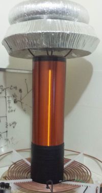
Class E? Class E...
ZakWolf, Tue Feb 16 2016, 07:46AMAlright, I have been here a long time and can say I have had hit and miss posts on here. I like 4hv and only come here and support this site and if i ask stupid questions im sorry.
To celebrate the purchase of my new oscilloscope I want to build a tiny, cool running, beautiful HFSSTC Class E coil.
Other then
 and
and  and
and  What else is there for resources? Do I need to just read about RF amp. designs ?
 Goals:
Higher the Mhz the better
Provide information for people like me
Fixed frequency
cool heatsinks ( happy fets)
I see mostly IRFP460's used... tell me is this a way better replacement ?
 1/8 of the Rds!! 3x current !!!
Is Erik T, Using rectified mains ?
 150v in?
 Power Input? I have this
 Or would mains work like Erik's 150v input (170v Smoothed)***
So What I gather is I need a fixed ossilation via crystal and I need to clean up the signal/ make it able to switch my
 on and off, tune coil via L and C? Bring (force) switching to ZVS of course
Additionally, interrupters... Staccato? Class E sword streamers?
Re: Class E? Class E...
Dr. Slack, Tue Feb 16 2016, 10:49AM
Your Mouser link with 1/8th rds, just goes to the main site and not the component. I would have thought that rDS was relatively unimportant compared to switching energy if you want MOAR MHz.
Dr. Slack, Tue Feb 16 2016, 10:49AM
Your Mouser link with 1/8th rds, just goes to the main site and not the component. I would have thought that rDS was relatively unimportant compared to switching energy if you want MOAR MHz.
Re: Class E? Class E...
ZakWolf, Tue Feb 16 2016, 04:19PM
Original post updated/fixed
ZakWolf, Tue Feb 16 2016, 04:19PM
Dr. Slack wrote ...
Your Mouser link with 1/8th rds, just goes to the main site and not the component. I would have thought that rDS was relatively unimportant compared to switching energy if you want MOAR MHz.
Your Mouser link with 1/8th rds, just goes to the main site and not the component. I would have thought that rDS was relatively unimportant compared to switching energy if you want MOAR MHz.
Original post updated/fixed
Re: Class E? Class E...
Inducktion, Tue Feb 16 2016, 07:01PM
I don't know much about class E, but I do know that switching times and gate capacitance are the biggest factors in determining how fast a fet can switch on and off. At the speeds you're switching the fets RDSon becomes the lesser of the two evils, and switching losses will dominate how much power you dissipate.
Hell even the driver and just discharging and recharging the gate capacitance can dissipate a decent amount of RF power alone.
Re: Class E? Class E...
jdub1581hv, Tue Feb 16 2016, 09:30PM
I too am diving into the class E and E/F(added harmonic filters, 2fo, 3fo, 5fo).
You forgot about Steve Wards class E S. Wards cESSTC
I was about to post the same topic, Mind if I piggyback?
For me however, I am looking into the lower F(res) 300khz - 600khz.
So here's what I found as the basic amp schematic:
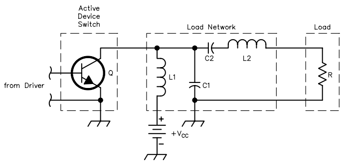
I did find this online Class E Calculator Class E Calculator ..
More for Radio work, so should help you with the high(er) MHZ
However there are a few things that I am unsure about as many I see only use L1 and C1 in regards to TC's.
(Forgive my ignorance if this sounds dumb, still tons I have no Idea about..)
Are C2-L2 the switches values or actual components? Or the combination/reduction of both?
jdub1581hv, Tue Feb 16 2016, 09:30PM
I too am diving into the class E and E/F(added harmonic filters, 2fo, 3fo, 5fo).
You forgot about Steve Wards class E S. Wards cESSTC
I was about to post the same topic, Mind if I piggyback?
For me however, I am looking into the lower F(res) 300khz - 600khz.
So here's what I found as the basic amp schematic:

I did find this online Class E Calculator Class E Calculator ..
More for Radio work, so should help you with the high(er) MHZ
However there are a few things that I am unsure about as many I see only use L1 and C1 in regards to TC's.
(Forgive my ignorance if this sounds dumb, still tons I have no Idea about..)
Are C2-L2 the switches values or actual components? Or the combination/reduction of both?
Re: Class E? Class E...
ZakWolf, Wed Feb 17 2016, 04:51AM
You may Piggy Back. More the merry.
I was also looking for RF Amps schematics around the 4Mhz area and have very little
Edit: Give this a read !!
!!
ZakWolf, Wed Feb 17 2016, 04:51AM
jdub1581hv wrote ...
I too am diving into the class E and E/F(added harmonic filters, 2fo, 3fo, 5fo).
You forgot about Steve Wards class E S. Wards cESSTC
I was about to post the same topic, Mind if I piggyback?
For me however, I am looking into the lower F(res) 300khz - 600khz.
So here's what I found as the basic amp schematic:

I did find this online Class E Calculator Class E Calculator ..
More for Radio work, so should help you with the high(er) MHZ
However there are a few things that I am unsure about as many I see only use L1 and C1 in regards to TC's.
(Forgive my ignorance if this sounds dumb, still tons I have no Idea about..)
Are C2-L2 the switches values or actual components? Or the combination/reduction of both?
I too am diving into the class E and E/F(added harmonic filters, 2fo, 3fo, 5fo).
You forgot about Steve Wards class E S. Wards cESSTC
I was about to post the same topic, Mind if I piggyback?
For me however, I am looking into the lower F(res) 300khz - 600khz.
So here's what I found as the basic amp schematic:

I did find this online Class E Calculator Class E Calculator ..
More for Radio work, so should help you with the high(er) MHZ
However there are a few things that I am unsure about as many I see only use L1 and C1 in regards to TC's.
(Forgive my ignorance if this sounds dumb, still tons I have no Idea about..)
Are C2-L2 the switches values or actual components? Or the combination/reduction of both?
You may Piggy Back. More the merry.
I was also looking for RF Amps schematics around the 4Mhz area and have very little
Edit: Give this a read
 !!
!!Re: Class E? Class E...
jdub1581hv, Wed Feb 17 2016, 08:59PM
So I fixed the calculator link (forgot to put the http in) .. Sorry bout that.
Also here is another good read.. helped me out at least though it is geared more to class F
Class F and Inverse class F
Covers it all as far as getting the design down, switching behavior, filtering etc..
I'm leaning more to the E/F hybrid myself, as to be both efficient and powerful (F is less efficient, yet more power out from what I read.. but can reach 100% as well with precision parts and design).
And also, I think the impedance matching and component reduction finally started making sense last night. For me only being able to read online and not converse with live people (aside from here) has made this quite the adventure...
I have a couple Cree SiC Mosfets 900v 36a I want to use for this, but for now I'm too timid and don't enjoy $10 smoke rings.
So for now I have 3 CEFF630 mfets, 10a, 650v, low Ciss 800pf / Coss 150pf , and rds of .27 - .4ohms
I'm a little worried about the dissipation only being 35W...
There also seems to be a lot of different ways to deal with drive signal, but I'm debating Res. Feedback vs Xtal .. I don't think the 4046 pll would have any problems, but I've read it has its own intrinsic flaws...
Still curious if anyone could give some design guidelines as far as where to start.. Start with resonator, fets, frequency? I've got about 15 resonators to choose from, starting: 1/2"dia x 3"
-> 6"dia x 24" , with a rough F range of 6mhz down to 150khz ...
Re: Class E? Class E...
jdub1581hv, Wed Feb 17 2016, 11:33PM
Another good read..
]hfe0111_firas.pdf[/file]
jdub1581hv, Wed Feb 17 2016, 11:33PM
Another good read..
]hfe0111_firas.pdf[/file]
Re: Class E? Class E...
ZakWolf, Thu Feb 18 2016, 12:08AM
Thanks I have been working so I havent had time to read till now. I found this its extensive and seems really organized [quote]
Another good read.. its also Class E/F design
ZakWolf, Thu Feb 18 2016, 12:08AM
jdub1581hv wrote ...
So I fixed the calculator link (forgot to put the http in) .. Sorry bout that.
Also here is another good read.. helped me out at least though it is geared more to class F
Class F and Inverse class F
Covers it all as far as getting the design down, switching behavior, filtering etc..
I'm leaning more to the E/F hybrid myself, as to be both efficient and powerful (F is less efficient, yet more power out from what I read.. but can reach 100% as well with precision parts and design).
And also, I think the impedance matching and component reduction finally started making sense last night. For me only being able to read online and not converse with live people (aside from here) has made this quite the adventure...
I have a couple Cree SiC Mosfets 900v 36a I want to use for this, but for now I'm too timid and don't enjoy $10 smoke rings.
So for now I have 3 CEFF630 mfets, 10a, 650v, low Ciss 800pf / Coss 150pf , and rds of .27 - .4ohms
I'm a little worried about the dissipation only being 35W...
There also seems to be a lot of different ways to deal with drive signal, but I'm debating Res. Feedback vs Xtal .. I don't think the 4046 pll would have any problems, but I've read it has its own intrinsic flaws...
Still curious if anyone could give some design guidelines as far as where to start.. Start with resonator, fets, frequency? I've got about 15 resonators to choose from, starting: 1/2"dia x 3"
-> 6"dia x 24" , with a rough F range of 6mhz down to 150khz ...
jdub1581hv wrote ...
Another good read..
Another good read..
Thanks I have been working so I havent had time to read till now. I found this its extensive and seems really organized [quote]
Another good read..
 its also Class E/F design
Re: Class E? Class E...
Inducktion, Thu Feb 18 2016, 01:41AM
jdub1581hv, you have to be careful with SiC Fet's.
Pay heavy attention to the voltage they can handle on their gates.... They do not tolerate negative swings more than like, -5 volts before they start to have issues/break down.
Inducktion, Thu Feb 18 2016, 01:41AM
jdub1581hv, you have to be careful with SiC Fet's.
Pay heavy attention to the voltage they can handle on their gates.... They do not tolerate negative swings more than like, -5 volts before they start to have issues/break down.
Re: Class E? Class E...
ZakWolf, Thu Feb 18 2016, 02:05AM
[quote]
 This is a step by step design for class e power amp MUST READ !!
What do i check for in the specs to calculate the switching speed max? There has to be something better then an IRFP460 fet
Edit: Try out multi sim blue, Mouser offers it free with there parts database to simulate circuits
ZakWolf, Thu Feb 18 2016, 02:05AM
[quote]
jdub1581hv wrote ...
So I fixed the calculator link (forgot to put the http in) .. Sorry bout that.
Also here is another good read.. helped me out at least though it is geared more to class F
Class F and Inverse class F
Covers it all as far as getting the design down, switching behavior, filtering etc..
I'm leaning more to the E/F hybrid myself, as to be both efficient and powerful (F is less efficient, yet more power out from what I read.. but can reach 100% as well with precision parts and design).
And also, I think the impedance matching and component reduction finally started making sense last night. For me only being able to read online and not converse with live people (aside from here) has made this quite the adventure...
I have a couple Cree SiC Mosfets 900v 36a I want to use for this, but for now I'm too timid and don't enjoy $10 smoke rings.
So for now I have 3 CEFF630 mfets, 10a, 650v, low Ciss 800pf / Coss 150pf , and rds of .27 - .4ohms
I'm a little worried about the dissipation only being 35W...
There also seems to be a lot of different ways to deal with drive signal, but I'm debating Res. Feedback vs Xtal .. I don't think the 4046 pll would have any problems, but I've read it has its own intrinsic flaws...
Still curious if anyone could give some design guidelines as far as where to start.. Start with resonator, fets, frequency? I've got about 15 resonators to choose from, starting: 1/2"dia x 3"
-> 6"dia x 24" , with a rough F range of 6mhz down to 150khz ...
jdub1581hv wrote ...
Another good read..
Another good read..
 This is a step by step design for class e power amp MUST READ !!
 Inducktion wrote ...
jdub1581hv, you have to be careful with SiC Fet's.
Pay heavy attention to the voltage they can handle on their gates.... They do not tolerate negative swings more than like, -5 volts before they start to have issues/break down.
jdub1581hv, you have to be careful with SiC Fet's.
Pay heavy attention to the voltage they can handle on their gates.... They do not tolerate negative swings more than like, -5 volts before they start to have issues/break down.
What do i check for in the specs to calculate the switching speed max? There has to be something better then an IRFP460 fet
Edit: Try out multi sim blue, Mouser offers it free with there parts database to simulate circuits
Re: Class E? Class E...
Chris_Knight, Thu Feb 18 2016, 04:49AM
What about the secondary coilform in class E tesla coils? Is there any data on ideal height, turns ratio, wire, form material. PVC has pretty bad dielectric losses at 4Mhz, does that really make a difference in the big scheme of things?
Chris_Knight, Thu Feb 18 2016, 04:49AM
What about the secondary coilform in class E tesla coils? Is there any data on ideal height, turns ratio, wire, form material. PVC has pretty bad dielectric losses at 4Mhz, does that really make a difference in the big scheme of things?
Re: Class E? Class E...
jdub1581hv, Thu Feb 18 2016, 04:55AM
Yup .. I am aware :) .. I 'try' to get as much info beforehand as possible. I am saving these as I said for when I get a stable circuit going.. Through the Cree website I was able to download schematics for an 8kw SiCfet 3 level resonant ZVS driver, with a nice section on the drive circuitry. Need to adapt for my switches, but a good reference none the least.
I'm also aiming for the lower F due to not having a real scope. Right now I'm running an arduino scope / LCF meter with lcd (yeah I know... -_-) but it's fairly accurate for what it can do. Especially for measuring the inductors at small values and caps into low pf up to about 1mf (added circuitry) so that's at least been a help.
(Anyone who wants the code let me know, I did not write it, though fixed a lot of code errors and adapted it to the seeed2.8"tft)
I'll apologize up front for the ton of questions and long-fingeredness.
I did attach the ZVS schem though for those who want it, or go get the whole package yourself.
]zvs_schematic_v3.pdf[/file]
jdub1581hv, Thu Feb 18 2016, 04:55AM
Inducktion wrote ...
jdub1581hv, you have to be careful with SiC Fet's.
Pay heavy attention to the voltage they can handle on their gates.... They do not tolerate negative swings more than like, -5 volts before they start to have issues/break down.
jdub1581hv, you have to be careful with SiC Fet's.
Pay heavy attention to the voltage they can handle on their gates.... They do not tolerate negative swings more than like, -5 volts before they start to have issues/break down.
Yup .. I am aware :) .. I 'try' to get as much info beforehand as possible. I am saving these as I said for when I get a stable circuit going.. Through the Cree website I was able to download schematics for an 8kw SiCfet 3 level resonant ZVS driver, with a nice section on the drive circuitry. Need to adapt for my switches, but a good reference none the least.
I'm also aiming for the lower F due to not having a real scope. Right now I'm running an arduino scope / LCF meter with lcd (yeah I know... -_-) but it's fairly accurate for what it can do. Especially for measuring the inductors at small values and caps into low pf up to about 1mf (added circuitry) so that's at least been a help.
(Anyone who wants the code let me know, I did not write it, though fixed a lot of code errors and adapted it to the seeed2.8"tft)
I'll apologize up front for the ton of questions and long-fingeredness.
I did attach the ZVS schem though for those who want it, or go get the whole package yourself.
]zvs_schematic_v3.pdf[/file]
Re: Class E? Class E...
jdub1581hv, Thu Feb 18 2016, 05:11AM
RDS, Ciss, Coss, Rise and Fall time . Some switches have a large tail current that makes them turn off slow
But I'll leave the rest to the better explained.. as many more factors play a role.
jdub1581hv, Thu Feb 18 2016, 05:11AM
ZakWolf wrote ...
What do i check for in the specs to calculate the switching speed max? There has to be something better then an IRFP460 fet
Edit: Try out multi sim blue, Mouser offers it free with there parts database to simulate circuits
What do i check for in the specs to calculate the switching speed max? There has to be something better then an IRFP460 fet
Edit: Try out multi sim blue, Mouser offers it free with there parts database to simulate circuits
RDS, Ciss, Coss, Rise and Fall time . Some switches have a large tail current that makes them turn off slow
But I'll leave the rest to the better explained.. as many more factors play a role.
Re: Class E? Class E...
ZakWolf, Thu Feb 18 2016, 05:34AM
How do you ground a HFSSTC ?
ZakWolf, Thu Feb 18 2016, 05:34AM
How do you ground a HFSSTC ?
Re: Class E? Class E...
jdub1581hv, Thu Feb 18 2016, 09:02PM
Many say a counterpoise would work though Ive had no probs with connecting to mains ground.. Really depends on environment and how anal you want to be...
jdub1581hv, Thu Feb 18 2016, 09:02PM
ZakWolf wrote ...
How do you ground a HFSSTC ?
How do you ground a HFSSTC ?
Many say a counterpoise would work though Ive had no probs with connecting to mains ground.. Really depends on environment and how anal you want to be...
Re: Class E? Class E...
ZakWolf, Thu Feb 18 2016, 11:00PM
Gotcha
So would a mains power design be possible? From what I have read the power needs to stay pretty constant to feed the MOSFET class e portion. I think is not using 150v as it says in his schematic since the MOSFET sees about 3.5 times the input voltage. Not possible with at least that FET. I think he meant 50v, if you look closely in the background of his close up shots of the coil you can see the yellow and black twisted pair of wire going to his 50v power supply he made in another project. However,
  powers his from 150v. Is it actually 150v or 170v as it becomes after being filtered?!?
ZakWolf, Thu Feb 18 2016, 11:00PM
jdub1581hv wrote ...
Many say a counterpoise would work though Ive had no probs with connecting to mains ground.. Really depends on environment and how anal you want to be...
ZakWolf wrote ...
How do you ground a HFSSTC ?
How do you ground a HFSSTC ?
Many say a counterpoise would work though Ive had no probs with connecting to mains ground.. Really depends on environment and how anal you want to be...
Gotcha
So would a mains power design be possible? From what I have read the power needs to stay pretty constant to feed the MOSFET class e portion. I think
 is not using 150v as it says in his schematic since the MOSFET sees about 3.5 times the input voltage. Not possible with at least that FET. I think he meant 50v, if you look closely in the background of his close up shots of the coil you can see the yellow and black twisted pair of wire going to his 50v power supply he made in another project. However,
  powers his from 150v. Is it actually 150v or 170v as it becomes after being filtered?!?
Re: Class E? Class E...
jdub1581hv, Fri Feb 19 2016, 01:20AM
Well he's probably using a doubler/3x , regarding his voltage.. And yes at Mains voltage you would want a fet around 4.5x the input, includes a safety margin.
Look at Steve Wards again... He had up to 150v over what it should have been... Which is probably why a few of my early on attempts blew up..
jdub1581hv, Fri Feb 19 2016, 01:20AM
ZakWolf wrote ...
Gotcha
So would a mains power design be possible? From what I have read the power needs to stay pretty constant to feed the MOSFET class e portion. I think is not using 150v as it says in his schematic since the MOSFET sees about 3.5 times the input voltage. Not possible with at least that FET. I think he meant 50v, if you look closely in the background of his close up shots of the coil you can see the yellow and black twisted pair of wire going to his 50v power supply he made in another project. However,
  powers his from 150v. Is it actually 150v or 170v as it becomes after being filtered?!?
Gotcha
So would a mains power design be possible? From what I have read the power needs to stay pretty constant to feed the MOSFET class e portion. I think
 is not using 150v as it says in his schematic since the MOSFET sees about 3.5 times the input voltage. Not possible with at least that FET. I think he meant 50v, if you look closely in the background of his close up shots of the coil you can see the yellow and black twisted pair of wire going to his 50v power supply he made in another project. However,
  powers his from 150v. Is it actually 150v or 170v as it becomes after being filtered?!?
Well he's probably using a doubler/3x , regarding his voltage.. And yes at Mains voltage you would want a fet around 4.5x the input, includes a safety margin.
Look at Steve Wards again... He had up to 150v over what it should have been... Which is probably why a few of my early on attempts blew up..
Re: Class E? Class E...
Chris_Knight, Sun Feb 21 2016, 05:37AM
What is a good ultrafast, low capacitance MOSFET for single ended class E? I'm having difficulty choosing a MOSFET balancing higher input voltage for more power, vs lower gate capacitance for faster switching. Right now I'm using the IRF630
Chris_Knight, Sun Feb 21 2016, 05:37AM
What is a good ultrafast, low capacitance MOSFET for single ended class E? I'm having difficulty choosing a MOSFET balancing higher input voltage for more power, vs lower gate capacitance for faster switching. Right now I'm using the IRF630
Re: Class E? Class E...
jdub1581hv, Sun Feb 21 2016, 09:02PM
I am wondering too...
With class E I think(?) the Zin -> Zout is the more important factor..
So you'd have to look at how the Ciss reacts at your frequency and balace with the load .. For many switches the Ciss seems to average around 2nf..
But these are assumptions on my part so don't take it verbatim...
jdub1581hv, Sun Feb 21 2016, 09:02PM
Chris_Knight wrote ...
What is a good ultrafast, low capacitance MOSFET for single ended class E? I'm having difficulty choosing a MOSFET balancing higher input voltage for more power, vs lower gate capacitance for faster switching. Right now I'm using the IRF630
What is a good ultrafast, low capacitance MOSFET for single ended class E? I'm having difficulty choosing a MOSFET balancing higher input voltage for more power, vs lower gate capacitance for faster switching. Right now I'm using the IRF630
I am wondering too...
With class E I think(?) the Zin -> Zout is the more important factor..
So you'd have to look at how the Ciss reacts at your frequency and balace with the load .. For many switches the Ciss seems to average around 2nf..
But these are assumptions on my part so don't take it verbatim...
Re: Class E? Class E...
Sulaiman, Sun Feb 21 2016, 09:35PM
I don't know if it helps but for simple amateur radio h.f. power amplifiers
IRF510s are popular because they are cheap, have relatively low capacitances,
and I've had them working at 14 MHz (20m).
They are only 100v, 4A cont., 20A peak but would be a cheap intro to h.f. Class-E
cheap enough to blow up a few whilst learning :)
Re: Class E? Class E...
jdub1581hv, Sun Feb 21 2016, 10:35PM
And available at RadioShack... lol... my 1st Mosfet :)
jdub1581hv, Sun Feb 21 2016, 10:35PM
Sulaiman wrote ...
I don't know if it helps but for simple amateur radio h.f. power amplifiers
IRF510s are popular because they are cheap, have relatively low capacitances,
and I've had them working at 14 MHz (20m).
They are only 100v, 4A cont., 20A peak but would be a cheap intro to h.f. Class-E
cheap enough to blow up a few whilst learning :)
And available at RadioShack... lol... my 1st Mosfet :)
Re: Class E? Class E...
ZakWolf, Tue Feb 23 2016, 02:46AM
Can I use my sn74hc14 to find the Res frequency of my secondary? Since I dont have a function generator or the money to get a worthwhile one I was wondering if the hex inverter would be able to do the trick.
300khz-~6Mhz sweep ability at 5.6v peak. Connected like this:
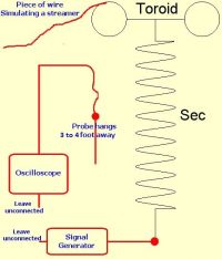
Would that supply an accurate reading? I havent dont much tuning before.
Also Im not this far along in my project yet but I was wondering if there was any good site for how to layout RF boards. From what I have read a good layout can do wonders. I noticed that just used through hole parts. Just looking for food for thought.
ZakWolf, Tue Feb 23 2016, 02:46AM
Can I use my sn74hc14 to find the Res frequency of my secondary? Since I dont have a function generator or the money to get a worthwhile one I was wondering if the hex inverter would be able to do the trick.
300khz-~6Mhz sweep ability at 5.6v peak. Connected like this:

Would that supply an accurate reading? I havent dont much tuning before.
Also Im not this far along in my project yet but I was wondering if there was any good site for how to layout RF boards. From what I have read a good layout can do wonders. I noticed that
 just used through hole parts. Just looking for food for thought.
Re: Class E? Class E...
GrantX, Tue Feb 23 2016, 07:55AM
This page has the relevant info on the 74C14, including the schematics and calculators for setting up the oscillator:
And this schematic I just found on google images shows roughly how to connect the oscillator to the parallel bank of gates (the gate with pins 3 and 4 is unnecessary and can be included in the parallel bank. Resistors in series with the output of each gate in the parallel bank are advised for current sharing purposes as I said before. Its also a good idea to include a resistor in series with the potentiometer so you can't turn it all the way to 0 Ohms):
That method of tuning seems reasonably accurate. I've had successful measurements by leaving the scope ground and signal-gen ground unconnected, but when using my lower power battery operated signal-gen I had to connect it to the scope ground to get a large enough signal.
As for RF layouts, it kind of depends what construction techniques you want to use or avoid. If you want to have some PCB's made up, a two layer board with generous ground planes and short thick traces will be beneficial. If you want something cheaper and easier, "point-to-point" or "dead-bug" techniques built on a copper ground plane will probably be the easiest to solder. Its mostly all about the shortest possible connections to avoid stray inductance, decoupling caps on all DC rails and shielding or ground planes everywhere possible.
For the handmade approach, these 3 Youtube videos may give you some inspiration:
- Construction and prototyping techniques:
- Building a RF crystal oscillator:
- Building CW transmitter and low pass filter:
GrantX, Tue Feb 23 2016, 07:55AM
ZakWolf wrote ...
Can I use my sn74hc14 to find the Res frequency of my secondary? Since I dont have a function generator or the money to get a worthwhile one I was wondering if the hex inverter would be able to do the trick.
300khz-~6Mhz sweep ability at 5.6v peak. Connected like this:

Would that supply an accurate reading? I havent dont much tuning before.
Also Im not this far along in my project yet but I was wondering if there was any good site for how to layout RF boards. From what I have read a good layout can do wonders. I noticed that just used through hole parts. Just looking for food for thought.
You can set up the 74HC14 as a variable frequency oscillator, which can sweep a rather large frequency range. But for 350kHz all the way to 6MHz the 74AC14 may be needed (the online calculator I found just then for the 74C14 tops out at 2.5MHz if you stay within the recommended values). You may also need a few different sized timing caps, with a switch to select the range you want. With one of the Schmitt gates set up as an oscillator with potentiometer and timing caps, the other 5 gates can be wired in parallel for a bit more current (probably a good idea to include a resistor in series with each output to ensure even current sharing).Can I use my sn74hc14 to find the Res frequency of my secondary? Since I dont have a function generator or the money to get a worthwhile one I was wondering if the hex inverter would be able to do the trick.
300khz-~6Mhz sweep ability at 5.6v peak. Connected like this:

Would that supply an accurate reading? I havent dont much tuning before.
Also Im not this far along in my project yet but I was wondering if there was any good site for how to layout RF boards. From what I have read a good layout can do wonders. I noticed that
 just used through hole parts. Just looking for food for thought.
 This page has the relevant info on the 74C14, including the schematics and calculators for setting up the oscillator:

And this schematic I just found on google images shows roughly how to connect the oscillator to the parallel bank of gates (the gate with pins 3 and 4 is unnecessary and can be included in the parallel bank. Resistors in series with the output of each gate in the parallel bank are advised for current sharing purposes as I said before. Its also a good idea to include a resistor in series with the potentiometer so you can't turn it all the way to 0 Ohms):

That method of tuning seems reasonably accurate. I've had successful measurements by leaving the scope ground and signal-gen ground unconnected, but when using my lower power battery operated signal-gen I had to connect it to the scope ground to get a large enough signal.
As for RF layouts, it kind of depends what construction techniques you want to use or avoid. If you want to have some PCB's made up, a two layer board with generous ground planes and short thick traces will be beneficial. If you want something cheaper and easier, "point-to-point" or "dead-bug" techniques built on a copper ground plane will probably be the easiest to solder. Its mostly all about the shortest possible connections to avoid stray inductance, decoupling caps on all DC rails and shielding or ground planes everywhere possible.
For the handmade approach, these 3 Youtube videos may give you some inspiration:
- Construction and prototyping techniques:

- Building a RF crystal oscillator:

- Building CW transmitter and low pass filter:

Re: Class E? Class E...
Chris_Knight, Tue Feb 23 2016, 11:38PM
What are the guidelines for the RF choke value? I know a recommended core material is type 2 powered iron toroids
Chris_Knight, Tue Feb 23 2016, 11:38PM
What are the guidelines for the RF choke value? I know a recommended core material is type 2 powered iron toroids
Re: Class E? Class E...
ZakWolf, Wed Feb 24 2016, 12:18AM
Those videos were perfect you guys are batting 1000.
So I havent settled on a set frequency yet, Whats the trade off of higher Mhz's? I think ball park around 4Mhz will be good. Also read about not having a coil former for the secondary, something about winding it and gluing it then removing the secondary former to reduce losses in the coil former.
ZakWolf, Wed Feb 24 2016, 12:18AM
GrantX wrote ...
This page has the relevant info on the 74C14, including the schematics and calculators for setting up the oscillator:
And this schematic I just found on google images shows roughly how to connect the oscillator to the parallel bank of gates (the gate with pins 3 and 4 is unnecessary and can be included in the parallel bank. Resistors in series with the output of each gate in the parallel bank are advised for current sharing purposes as I said before. Its also a good idea to include a resistor in series with the potentiometer so you can't turn it all the way to 0 Ohms):
That method of tuning seems reasonably accurate. I've had successful measurements by leaving the scope ground and signal-gen ground unconnected, but when using my lower power battery operated signal-gen I had to connect it to the scope ground to get a large enough signal.
As for RF layouts, it kind of depends what construction techniques you want to use or avoid. If you want to have some PCB's made up, a two layer board with generous ground planes and short thick traces will be beneficial. If you want something cheaper and easier, "point-to-point" or "dead-bug" techniques built on a copper ground plane will probably be the easiest to solder. Its mostly all about the shortest possible connections to avoid stray inductance, decoupling caps on all DC rails and shielding or ground planes everywhere possible.
For the handmade approach, these 3 Youtube videos may give you some inspiration:
- Construction and prototyping techniques:
- Building a RF crystal oscillator:
- Building CW transmitter and low pass filter:
ZakWolf wrote ...
Can I use my sn74hc14 to find the Res frequency of my secondary? Since I dont have a function generator or the money to get a worthwhile one I was wondering if the hex inverter would be able to do the trick.
300khz-~6Mhz sweep ability at 5.6v peak. Connected like this:

Would that supply an accurate reading? I havent dont much tuning before.
Also Im not this far along in my project yet but I was wondering if there was any good site for how to layout RF boards. From what I have read a good layout can do wonders. I noticed that just used through hole parts. Just looking for food for thought.
You can set up the 74HC14 as a variable frequency oscillator, which can sweep a rather large frequency range. But for 350kHz all the way to 6MHz the 74AC14 may be needed (the online calculator I found just then for the 74C14 tops out at 2.5MHz if you stay within the recommended values). You may also need a few different sized timing caps, with a switch to select the range you want. With one of the Schmitt gates set up as an oscillator with potentiometer and timing caps, the other 5 gates can be wired in parallel for a bit more current (probably a good idea to include a resistor in series with each output to ensure even current sharing).Can I use my sn74hc14 to find the Res frequency of my secondary? Since I dont have a function generator or the money to get a worthwhile one I was wondering if the hex inverter would be able to do the trick.
300khz-~6Mhz sweep ability at 5.6v peak. Connected like this:

Would that supply an accurate reading? I havent dont much tuning before.
Also Im not this far along in my project yet but I was wondering if there was any good site for how to layout RF boards. From what I have read a good layout can do wonders. I noticed that
 just used through hole parts. Just looking for food for thought.
 This page has the relevant info on the 74C14, including the schematics and calculators for setting up the oscillator:

And this schematic I just found on google images shows roughly how to connect the oscillator to the parallel bank of gates (the gate with pins 3 and 4 is unnecessary and can be included in the parallel bank. Resistors in series with the output of each gate in the parallel bank are advised for current sharing purposes as I said before. Its also a good idea to include a resistor in series with the potentiometer so you can't turn it all the way to 0 Ohms):

That method of tuning seems reasonably accurate. I've had successful measurements by leaving the scope ground and signal-gen ground unconnected, but when using my lower power battery operated signal-gen I had to connect it to the scope ground to get a large enough signal.
As for RF layouts, it kind of depends what construction techniques you want to use or avoid. If you want to have some PCB's made up, a two layer board with generous ground planes and short thick traces will be beneficial. If you want something cheaper and easier, "point-to-point" or "dead-bug" techniques built on a copper ground plane will probably be the easiest to solder. Its mostly all about the shortest possible connections to avoid stray inductance, decoupling caps on all DC rails and shielding or ground planes everywhere possible.
For the handmade approach, these 3 Youtube videos may give you some inspiration:
- Construction and prototyping techniques:

- Building a RF crystal oscillator:

- Building CW transmitter and low pass filter:

Those videos were perfect you guys are batting 1000.
So I havent settled on a set frequency yet, Whats the trade off of higher Mhz's? I think ball park around 4Mhz will be good. Also read about not having a coil former for the secondary, something about winding it and gluing it then removing the secondary former to reduce losses in the coil former.
Re: Class E? Class E...
jdub1581hv, Wed Feb 24 2016, 01:00AM
Being newb myself and having gone through much of this recently...
I think you'll find the higher frequencies are more demanding on your parts. I started with a small coil around 2mhz Fr, and have since built Many resonators to accommodate different circuits and switches (also more wire on 10# spool than I thought {6"x23" coil barely made a dent... lol}) .
An almost surefire setup is using direct 2ndry feedback, or an Antenna/Current transformer on secondary. Makes the drive circuitry much easier (at least for me).
I'd also think that the former will have little effect outside of really high power levels.. A small 4mhz coil should be fine with pvc, cardboard, waterbottles/ plactic containers.
My best performing small coil uses a Metamucil container (roughly 4"dia x 7" of windings .. I used #28 wire, gave me right at 500 turns) with 10"~ arcs (160vdc bus) using a pll driver and single switch.
Resonant Freq is just under 700khz, and about 650khz with an hdd platter for top load.
'Smart Water' are my bottles of choice when looking for cheap and fast, They are tall and straight, and the screw top allows for mounting hdd platters with little modification as well..
But, that's just what I have done and have not had any probs... Other than over powering my switches...
Also the smaller, higher F coils don't like much of a top load, which makes those platters pretty useful..
Also I go wider with former if needing to increase inductance rather than taller ..
Hopefully finishing up my circuit this eve, and I'll post some pics when running well.. and perhaps a family photo of the coils.
jdub1581hv, Wed Feb 24 2016, 01:00AM
ZakWolf wrote ...
Those videos were perfect you guys are batting 1000.
So I havent settled on a set frequency yet, Whats the trade off of higher Mhz's? I think ball park around 4Mhz will be good. Also read about not having a coil former for the secondary, something about winding it and gluing it then removing the secondary former to reduce losses in the coil former.
Being newb myself and having gone through much of this recently...
I think you'll find the higher frequencies are more demanding on your parts. I started with a small coil around 2mhz Fr, and have since built Many resonators to accommodate different circuits and switches (also more wire on 10# spool than I thought {6"x23" coil barely made a dent... lol}) .
An almost surefire setup is using direct 2ndry feedback, or an Antenna/Current transformer on secondary. Makes the drive circuitry much easier (at least for me).
I'd also think that the former will have little effect outside of really high power levels.. A small 4mhz coil should be fine with pvc, cardboard, waterbottles/ plactic containers.
My best performing small coil uses a Metamucil container (roughly 4"dia x 7" of windings .. I used #28 wire, gave me right at 500 turns) with 10"~ arcs (160vdc bus) using a pll driver and single switch.
Resonant Freq is just under 700khz, and about 650khz with an hdd platter for top load.
'Smart Water' are my bottles of choice when looking for cheap and fast, They are tall and straight, and the screw top allows for mounting hdd platters with little modification as well..
But, that's just what I have done and have not had any probs... Other than over powering my switches...
Also the smaller, higher F coils don't like much of a top load, which makes those platters pretty useful..
Also I go wider with former if needing to increase inductance rather than taller ..
Hopefully finishing up my circuit this eve, and I'll post some pics when running well.. and perhaps a family photo of the coils.
Re: Class E? Class E...
ZakWolf, Wed Feb 24 2016, 06:37AM
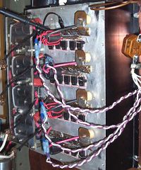
Paralleling MOSFETS ? The author says "The picture to the right shows a class E RF amplifier consisting of 4 modules of 5 MOSFETs per module. The 4 output transformers can be seen in the background, under a plexiglass sheet added for mechanical stability." Is he stacking the Source to Source, Gate to Gate , and Drain to Drain???
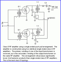
I ask because I plan on using rectified mains and this configuration will help share the current load per FET right ? I was going to use these, FQA11N90 same one the author uses in his circuits. So with the attached circuit I could ad say two FET's per side. Using a GDT to flip phase of the output of course. About to do all my maths and trying to get all my ducks in a row... FML
ZakWolf, Wed Feb 24 2016, 06:37AM
Paralleling MOSFETS ?
 The author says "The picture to the right shows a class E RF amplifier consisting of 4 modules of 5 MOSFETs per module. The 4 output transformers can be seen in the background, under a plexiglass sheet added for mechanical stability." Is he stacking the Source to Source, Gate to Gate , and Drain to Drain???

I ask because I plan on using rectified mains and this configuration will help share the current load per FET right ? I was going to use these, FQA11N90 same one the author uses in his circuits. So with the attached circuit I could ad say two FET's per side. Using a GDT to flip phase of the output of course. About to do all my maths and trying to get all my ducks in a row... FML
Re: Class E? Class E...
jdub1581hv, Wed Feb 24 2016, 05:52PM
I have not had to do much paralleling, but I believe you would want to use separate resistors on each gate for load sharing.
I'd try to avoid making it too complex.. More area for fault..
Not sure if you have one, But you could use a MOT for a current limiting ballast.. Put the primary in series before your rectifier..
A variac would be key though.
Re: Class E? Class E...
ZakWolf, Sat Feb 27 2016, 06:15AM
Alright, here is a little update on my progress. Planning on making a projects thread after I get a couple things worked out. Then the real building can begin.
Secondary specs: (metric)
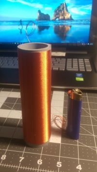
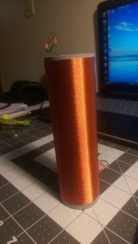
• Size:
o 43.15mm dia.
o 135.74mm tall
• Wire: homemade litz
o 3 strands of 32awg twisted
 .45mm wire dia. with all strands
o 301.64 turns
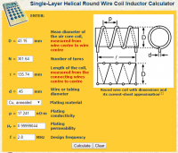
• Measurements
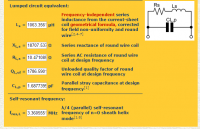
o 1020uH
o 7.6Ω (DC resistance(tested with multimeter))
o 2.8MHz Resf (measured with scope)
o 3.17pf self-capacitance
• Website calculations: and
and 
o Assuming the website only calculated one Single wire as the conductor may not be accurate
 56Ω AC ???
 794.19 Qu ???
Questions:
1.How do I calculate or what process determines my RFC for the circuit. I see Richie and Erik both use 47uH. How did they get this value, changing the L of the choke changes how much current is dumped into each cycle right?
2.Shunt capacitors: I read that high quality multi-layer ceramics are used a lot in RF applications. Choosing the right value for a tuned circuit/testing at lower power levels. Can I get like 100pf caps and keep soldering them on to keep the coil in tune.
3.DC blocking cap before the primary, Richie used 100nf and Erik used 47nf. More is better?
After I get this sorted I will make a projects thread and link it to here. Thanks for the help I appreciate it!!
4. Will this MOSFET work I see this guy always uses them
ZakWolf, Sat Feb 27 2016, 06:15AM
Alright, here is a little update on my progress. Planning on making a projects thread after I get a couple things worked out. Then the real building can begin.
Secondary specs: (metric)


• Size:
o 43.15mm dia.
o 135.74mm tall
• Wire: homemade litz
o 3 strands of 32awg twisted
 .45mm wire dia. with all strands
o 301.64 turns
• Measurements
o 1020uH
o 7.6Ω (DC resistance(tested with multimeter))
o 2.8MHz Resf (measured with scope)
o 3.17pf self-capacitance
• Website calculations:
 and
and 
o Assuming the website only calculated one Single wire as the conductor may not be accurate
 56Ω AC ???
 794.19 Qu ???


Questions:
1.How do I calculate or what process determines my RFC for the circuit. I see Richie and Erik both use 47uH. How did they get this value, changing the L of the choke changes how much current is dumped into each cycle right?
2.Shunt capacitors: I read that high quality multi-layer ceramics are used a lot in RF applications. Choosing the right value for a tuned circuit/testing at lower power levels. Can I get like 100pf caps and keep soldering them on to keep the coil in tune.
3.DC blocking cap before the primary, Richie used 100nf and Erik used 47nf. More is better?
After I get this sorted I will make a projects thread and link it to here. Thanks for the help I appreciate it!!
4. Will this MOSFET work
 I see this guy always uses them
Re: Class E? Class E...
Chris_Knight, Sat Feb 27 2016, 07:22AM
Does the litz wire help? I've always assumed that the primary has so great losses, what you save in the secondary doesn't make much difference. Plus, you're going to loose a good amount of RF energy heating up that PVC former.
I was unsure about the RFC too. The RFC blocks AC and passes DC. Therefore, the inductance of the choke has to present an much higher impedance to AC than the load resistance. I'm not sure what's a minimum acceptable value, Richie and Uzzors2k use 56/47 uH, like you said, but Reaching uses a 470uH, which is an order of magnitude difference.
One thing I do know that it's best to use a powered iron core that's rated for these frequencies, so type 2 is usually recommended. It has a very low AL value, so 470uH isn't that easy, I bought some 3" diameter T300 size cores that I have to wind ~200 or so turns to get 470uH. About 70 turns for 47uH though, which is more manageable.
I personally like to use mica capacitors or film capacitors, like PP or polystyrene.
For the DC blocking cap, greater capacitance can pass more current. So it doesn't hurt to have a higher value, but it probably won't make a difference.
That has an awfully high Rds(ON) @ .98 . You're going to have very high I2R losses.
Re: Class E? Class E...
ZakWolf, Sat Feb 27 2016, 07:50AM
Litz makes a world of difference when it comes to HF and skin effect. The primary will also be litz and be comprised of 19 strands of 32 awg wire.
From what I have been reading and understand is that the Rds on goes out the window compared to the capacitance of the gate. If the device cannot turn on/off fast enough the Rds doesnt matter.
I am just trying to get my cart all full so I dont have to pay twice for shipping on something I forgot to get
edit: litz also reduces the amount of heating due to the lower resistance of the wire at RF
ZakWolf, Sat Feb 27 2016, 07:50AM
Chris_Knight wrote ...
Does the litz wire help? I've always assumed that the primary has so great losses, what you save in the secondary doesn't make much difference. Plus, you're going to loose a good amount of RF energy heating up that PVC former.
I was unsure about the RFC too. The RFC blocks AC and passes DC. Therefore, the inductance of the choke has to present an much higher impedance to AC than the load resistance. I'm not sure what's a minimum acceptable value, Richie and Uzzors2k use 56/47 uH, like you said, but Reaching uses a 470uH, which is an order of magnitude difference.
One thing I do know that it's best to use a powered iron core that's rated for these frequencies, so type 2 is usually recommended. It has a very low AL value, so 470uH isn't that easy, I bought some 3" diameter T300 size cores that I have to wind ~200 or so turns to get 470uH. About 70 turns for 47uH though, which is more manageable.
I personally like to use mica capacitors or film capacitors, like PP or polystyrene.
For the DC blocking cap, greater capacitance can pass more current. So it doesn't hurt to have a higher value, but it probably won't make a difference.
That has an awfully high Rds(ON) @ .98 . You're going to have very high I2R losses.
Litz makes a world of difference when it comes to HF and skin effect. The primary will also be litz and be comprised of 19 strands of 32 awg wire.
From what I have been reading and understand is that the Rds on goes out the window compared to the capacitance of the gate. If the device cannot turn on/off fast enough the Rds doesnt matter.
I am just trying to get my cart all full so I dont have to pay twice for shipping on something I forgot to get
edit: litz also reduces the amount of heating due to the lower resistance of the wire at RF
Re: Class E? Class E...
Chris_Knight, Sat Feb 27 2016, 08:31AM
Well I mean you want to balance both gate capacitance and Rds(ON). Both matter. Plus, your chosen transistor doesn't even have that low a gate capacitance. Total gate charge is 72nC, compared the 43 of the old IRF630, which has half the Rds(ON)! Plus, the IRF630 has less than half the switching times. The main advantage of that FQA11N90_F109 is the much higher Vds, but that really is pointless unless you're planning to run your coil at 700v Vcc or something. So I don't get it, unless I'm missing something here.
I'm not arguing that litz is better at RF. My argument is that in Class E sstc work, your savings in using litz are heavily outweighed by your losses elsewhere in the system. But I may be wrong. It's certainly worthwhile to try!
Re: Class E? Class E...
Wolfram, Sat Feb 27 2016, 01:32PM
In class E amplifiers, the peak drain voltage is close to three times the supply voltage ( ), so the IRFP630 should not be used with supply voltages higher than approximately 60 V DC. The FQA11N90 could theoretically be used with supply voltages up to around 300 V DC, though some more safety margin is probably a good idea.
Wolfram, Sat Feb 27 2016, 01:32PM
Chris_Knight wrote ...
Well I mean you want to balance both gate capacitance and Rds(ON). Both matter. Plus, your chosen transistor doesn't even have that low a gate capacitance. Total gate charge is 72nC, compared the 43 of the old IRF630, which has half the Rds(ON)! Plus, the IRF630 has less than half the switching times. The main advantage of that FQA11N90_F109 is the much higher Vds, but that really is pointless unless you're planning to run your coil at 700v Vcc or something. So I don't get it, unless I'm missing something here.
Well I mean you want to balance both gate capacitance and Rds(ON). Both matter. Plus, your chosen transistor doesn't even have that low a gate capacitance. Total gate charge is 72nC, compared the 43 of the old IRF630, which has half the Rds(ON)! Plus, the IRF630 has less than half the switching times. The main advantage of that FQA11N90_F109 is the much higher Vds, but that really is pointless unless you're planning to run your coil at 700v Vcc or something. So I don't get it, unless I'm missing something here.
In class E amplifiers, the peak drain voltage is close to three times the supply voltage (
 ), so the IRFP630 should not be used with supply voltages higher than approximately 60 V DC. The FQA11N90 could theoretically be used with supply voltages up to around 300 V DC, though some more safety margin is probably a good idea.
Re: Class E? Class E...
ZakWolf, Sat Feb 27 2016, 05:10PM
Yeah like wolfram said, when tuned properly the voltage is around 3.5 times the Vcc. Well how about this guy this is what Eastern Voltage uses in their coils.
ZakWolf, Sat Feb 27 2016, 05:10PM
Yeah like wolfram said, when tuned properly the voltage is around 3.5 times the Vcc. Well how about this guy
 this is what Eastern Voltage uses in their coils.
Re: Class E? Class E...
ZakWolf, Fri Mar 04 2016, 06:52AM
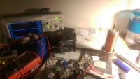
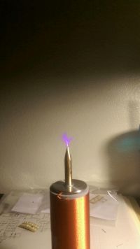
Got it up and running, running HOT and off of 50v. Why is my IXDD614 getting so hot?
ZakWolf, Fri Mar 04 2016, 06:52AM
Got it up and running, running HOT and off of 50v. Why is my IXDD614 getting so hot?


Re: Class E? Class E...
ZakWolf, Fri Mar 04 2016, 07:58AM
sorry for the double post wanted to include scope shot.
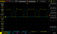
Yellow: IXDD614 output looks bad.. not sure why.
blue: drain. MOSFET gets hot fast
I have 440pf of shunt capacitance, 100nf DC blocking and 6 turns on the primary 18awg wire. 30uH for my RF choke. Its wound on #2 iron powder good between 2-8Mhz. Would more inductance help ? I couldnt find any information on choosing a value
edit: the coil also make a high pitch noise, like a screaming sound although its not really loud. I thought 3Mhz plasma was silent
ZakWolf, Fri Mar 04 2016, 07:58AM
sorry for the double post wanted to include scope shot.

Yellow: IXDD614 output looks bad.. not sure why.
blue: drain. MOSFET gets hot fast
I have 440pf of shunt capacitance, 100nf DC blocking and 6 turns on the primary 18awg wire. 30uH for my RF choke. Its wound on #2 iron powder good between 2-8Mhz. Would more inductance help ? I couldnt find any information on choosing a value
edit: the coil also make a high pitch noise, like a screaming sound although its not really loud. I thought 3Mhz plasma was silent
Re: Class E? Class E...
jdub1581hv, Fri Mar 04 2016, 02:54PM
I'd say start adjusting your coupling, from what I understand it's fairly critical with class E.
You may also need more shunt capacitance.. Go to Steve Wards link I posted and compare scope shots, he explains how he tuned his.
Yet he is not using a choke or blocking cap.. so .. I think it's Thevenin's theorem that plays a role in his setup (equivalent impedance's).
So did you go fixed osc. or feedback driven? that may help as well, try direct/coupled feedback?
Re: Class E? Class E...
ZakWolf, Sat Mar 05 2016, 07:21AM
fixed oscillation. ~2.88MHz.
switched out FET and got much better results ie. less heating. Tried mains and forgot to up my shunt capacitance which im sure cause a huge voltage spike killing the fet and shoring my IXDD frying both of the chips I had.
Ordering new parts..better ones?!? What would cause the IXDD614 to get burning hot olny after ~10 sec operation. I noticed that when the Fres. was below 1MHz the chip ran cool but and more then that and it got HOT fast. Im getting the TO-263-5 okg so I can mount it to the heatsink. Best results were about 1.5cm discharge with 36V unknown amp draw.
I will be back!!
ZakWolf, Sat Mar 05 2016, 07:21AM
jdub1581hv wrote ...
I'd say start adjusting your coupling, from what I understand it's fairly critical with class E.
You may also need more shunt capacitance.. Go to Steve Wards link I posted and compare scope shots, he explains how he tuned his.
Yet he is not using a choke or blocking cap.. so .. I think it's Thevenin's theorem that plays a role in his setup (equivalent impedance's).
So did you go fixed osc. or feedback driven? that may help as well, try direct/coupled feedback?
fixed oscillation. ~2.88MHz.
switched out FET and got much better results ie. less heating. Tried mains and forgot to up my shunt capacitance which im sure cause a huge voltage spike killing the fet and shoring my IXDD frying both of the chips I had.
Ordering new parts..better ones?!? What would cause the IXDD614 to get burning hot olny after ~10 sec operation. I noticed that when the Fres. was below 1MHz the chip ran cool but and more then that and it got HOT fast. Im getting the TO-263-5 okg so I can mount it to the heatsink. Best results were about 1.5cm discharge with 36V unknown amp draw.
I will be back!!
Re: Class E? Class E...
Wolfram, Sat Mar 05 2016, 01:06PM
What MOSFET are you using? At these frequencies, it doesn't take a huge amount of gate capacitance before the gate driver power dissipation becomes significant.
Wolfram, Sat Mar 05 2016, 01:06PM
What MOSFET are you using? At these frequencies, it doesn't take a huge amount of gate capacitance before the gate driver power dissipation becomes significant.
Re: Class E? Class E...
jdub1581hv, Sat Mar 05 2016, 04:33PM
Same boat, the ones I was using popped pretty quick using a set oscillator.. Direct fb lasted longer, but still died...
Guessing class E can't depend on Maths alone... Damn Scopes...
jdub1581hv, Sat Mar 05 2016, 04:33PM
ZakWolf wrote ...
fixed oscillation. ~2.88MHz.
switched out FET and got much better results ie. less heating. Tried mains and forgot to up my shunt capacitance which im sure cause a huge voltage spike killing the fet and shoring my IXDD frying both of the chips I had.
Ordering new parts..better ones?!? What would cause the IXDD614 to get burning hot olny after ~10 sec operation. I noticed that when the Fres. was below 1MHz the chip ran cool but and more then that and it got HOT fast. Im getting the TO-263-5 okg so I can mount it to the heatsink. Best results were about 1.5cm discharge with 36V unknown amp draw.
I will be back!!
Same boat, the ones I was using popped pretty quick using a set oscillator.. Direct fb lasted longer, but still died...
Guessing class E can't depend on Maths alone... Damn Scopes...
Re: Class E? Class E...
ZakWolf, Sat Mar 05 2016, 11:41PM
I used two MOSFETS and
and 
I was able to run the IXFH pretty cool but my drive chip was cooking.
Im going to try these out and switch my IXDD case type to this
  Its got dat heatsink ability ;)
Also picking up some more multi layer ceramics for greater range in my shunt choice and also grabbing more DC blocking caps so I can experiment with those values more.
This build is strictly to understand and learn how to produce a working and sturdy design.
The RF Choke !?! wtf correct me if im wrong. It builds up a EM field that collapses later after the switched is closed. More inductance causes a larger pulse of energy but Im assuming there is also a limit or at least a desired amount you would want. How to I go about calculating what I need. I have two of these cores Iron Powder Toroidal Cores
Type 2 material, AL=135, U=10
1.06" O.D. x 0.56" I.D. x 0.44" Hgt
2 MHz to 30 MHz. frequency range.
Manufacturer-Amidon
ZakWolf, Sat Mar 05 2016, 11:41PM
Wolfram wrote ...
What MOSFET are you using? At these frequencies, it doesn't take a huge amount of gate capacitance before the gate driver power dissipation becomes significant.
What MOSFET are you using? At these frequencies, it doesn't take a huge amount of gate capacitance before the gate driver power dissipation becomes significant.
I used two MOSFETS
 and
and 
I was able to run the IXFH pretty cool but my drive chip was cooking.
Im going to try these out
 and switch my IXDD case type to this
  Its got dat heatsink ability ;)
Also picking up some more multi layer ceramics for greater range in my shunt choice and also grabbing more DC blocking caps so I can experiment with those values more.
This build is strictly to understand and learn how to produce a working and sturdy design.
The RF Choke !?! wtf correct me if im wrong. It builds up a EM field that collapses later after the switched is closed. More inductance causes a larger pulse of energy but Im assuming there is also a limit or at least a desired amount you would want. How to I go about calculating what I need. I have two of these cores Iron Powder Toroidal Cores

Type 2 material, AL=135, U=10
1.06" O.D. x 0.56" I.D. x 0.44" Hgt
2 MHz to 30 MHz. frequency range.
Manufacturer-Amidon
Re: Class E? Class E...
jdub1581hv, Sun Mar 06 2016, 12:36AM
Well, 'most' other designs available don't use the choke or blocking cap..?
I still think you should at least try a feedback drive, antenna or current xfmr.. Maybe with a junk fet to test?
jdub1581hv, Sun Mar 06 2016, 12:36AM
Well, 'most' other designs available don't use the choke or blocking cap..?
I still think you should at least try a feedback drive, antenna or current xfmr.. Maybe with a junk fet to test?
Re: Class E? Class E...
ZakWolf, Sun Mar 06 2016, 01:04AM
I think you're mistaken all "class e" designs employ many capacitors in order to achieve the correct output. The "DC blocking" cap is just apart of tuning the circuit. The RF Choke is the same way. Its lossy so that HF AC doesnt pass through it easily or at all and allows DC to flow easily. How to determine these values im not sure. I wish I new how to to calculate the RF choke, maybe I will build it around the value of my choke, Since its easier to solder caps then rewind a core over and over.
Edit: What I dont get from other designs is that the Class e circuit is tuned to run at a certain power, voltage, and frequency. If you change any of those that effects the tuning. So if you use a any type of feedback it will change the frequency thus changing everything else. I think that would result in more heating than a fixed oscillator and every once in awhile pulling some arcs from it. Since the coil will be tune 99% of the time and only detuned when you pull an arc.
jdub1581hv, you build anything yet ? Pics ? specs?
ZakWolf, Sun Mar 06 2016, 01:04AM
jdub1581hv wrote ...
Well, 'most' other designs available don't use the choke or blocking cap..?
I still think you should at least try a feedback drive, antenna or current xfmr.. Maybe with a junk fet to test?
Well, 'most' other designs available don't use the choke or blocking cap..?
I still think you should at least try a feedback drive, antenna or current xfmr.. Maybe with a junk fet to test?
I think you're mistaken all "class e" designs employ many capacitors in order to achieve the correct output.
 The "DC blocking" cap is just apart of tuning the circuit. The RF Choke is the same way. Its lossy so that HF AC doesnt pass through it easily or at all and allows DC to flow easily. How to determine these values im not sure. I wish I new how to to calculate the RF choke, maybe I will build it around the value of my choke, Since its easier to solder caps then rewind a core over and over.
 Edit: What I dont get from other designs is that the Class e circuit is tuned to run at a certain power, voltage, and frequency. If you change any of those that effects the tuning. So if you use a any type of feedback it will change the frequency thus changing everything else. I think that would result in more heating than a fixed oscillator and every once in awhile pulling some arcs from it. Since the coil will be tune 99% of the time and only detuned when you pull an arc.
jdub1581hv, you build anything yet ? Pics ? specs?
Re: Class E? Class E...
jdub1581hv, Sun Mar 06 2016, 01:57AM
I guess I should correct myself, What I meant :
Thevenin's Theory says you can replace a complex impedance (LC / LCR tank) with an equivalent resistance (heavily paraphrased)
So in the other designs they have already reduced their components to a matching value, which is why I keep referring to Steve Wards setup..
He only has the primary and shunt cap, no RFC/Block cap. This is where my struggle is happening (aside from not having a oscope (-_-) ).
Trying to figure out how he got his cap values... He started with 2.2nf shunt (JavaTC value/ calc'd res?) and had to increase to 10nf to achieve class E.
Also he is using an antenna for fb.
Feedback from Sec. coil shouldn't cause problems, from what I understand, it keeps the current 90* out of phase with primary and will be in resonance with pri tank .. Like a Slayer Exciter.
Then you would want to run the tank slightly above resonance so that when you pull a load(arcing) it brings the circuit into proper resonance lowering frequency when a load is present.
I Could be completely wrong and hope I get corrected if so..
Another example from the forums here: Author: Perezx

Original Thread
I 'did' have pics, I got hacked and had to reinstall my OS .. Had no way to save ANYTHING >!< all my pics, programs, arduino projects, javafx projects... I do have a pic on phone of coil I'm working on now.. (Ditching class E till I can get a scope)
Dimensions: 6" X 24" X 1600t #28 wire
Res Freq : 145khz with topload(upper one), 165+/- khz without
jdub1581hv, Sun Mar 06 2016, 01:57AM
I guess I should correct myself, What I meant :
Thevenin's Theory says you can replace a complex impedance (LC / LCR tank) with an equivalent resistance (heavily paraphrased)
So in the other designs they have already reduced their components to a matching value, which is why I keep referring to Steve Wards setup..
He only has the primary and shunt cap, no RFC/Block cap. This is where my struggle is happening (aside from not having a oscope (-_-) ).
Trying to figure out how he got his cap values... He started with 2.2nf shunt (JavaTC value/ calc'd res?) and had to increase to 10nf to achieve class E.
Also he is using an antenna for fb.
Feedback from Sec. coil shouldn't cause problems, from what I understand, it keeps the current 90* out of phase with primary and will be in resonance with pri tank .. Like a Slayer Exciter.
Then you would want to run the tank slightly above resonance so that when you pull a load(arcing) it brings the circuit into proper resonance lowering frequency when a load is present.
I Could be completely wrong and hope I get corrected if so..
Another example from the forums here: Author: Perezx

Original Thread
I 'did' have pics, I got hacked and had to reinstall my OS .. Had no way to save ANYTHING >!< all my pics, programs, arduino projects, javafx projects... I do have a pic on phone of coil I'm working on now.. (Ditching class E till I can get a scope)
Dimensions: 6" X 24" X 1600t #28 wire
Res Freq : 145khz with topload(upper one), 165+/- khz without
Re: Class E? Class E...
Claude, Sun Mar 06 2016, 10:56PM
I have built this 4Mhz class E coil by Reaching. It's simple and works very well.
Claude.
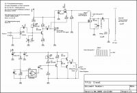
Claude, Sun Mar 06 2016, 10:56PM
I have built this 4Mhz class E coil by Reaching. It's simple and works very well.
Claude.

Re: Class E? Class E...
Claude, Sun Mar 06 2016, 11:06PM
Sorry,this is the updated schematic that I used. You don't have to use the audio modulation if you don't want to.
Claude.
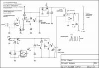
Claude, Sun Mar 06 2016, 11:06PM
Sorry,this is the updated schematic that I used. You don't have to use the audio modulation if you don't want to.
Claude.

Re: Class E? Class E...
Chris_Knight, Mon Mar 07 2016, 03:42PM
I might be wrong, but a variable air capacitor could be used for the tank capacitor for better tuning. The radio type have a capacitance of 365pf.
Or maybe a constant value capacitor with a 30pf air trimmer, like the kind used in transmitters.
Chris_Knight, Mon Mar 07 2016, 03:42PM
I might be wrong, but a variable air capacitor could be used for the tank capacitor for better tuning. The radio type have a capacitance of 365pf.
Or maybe a constant value capacitor with a 30pf air trimmer, like the kind used in transmitters.
Re: Class E? Class E...
woodchuck, Mon Mar 07 2016, 10:33PM
Don't know German but the schematic seems to indicate that the secondary is 5cm in diameter and a mere 7.5 cm long. With these diminutive dimensions and a 4MHz operating frequency, what sort of brush/spark discharge does it produce?
woodchuck, Mon Mar 07 2016, 10:33PM
Don't know German but the schematic seems to indicate that the secondary is 5cm in diameter and a mere 7.5 cm long. With these diminutive dimensions and a 4MHz operating frequency, what sort of brush/spark discharge does it produce?
Re: Class E? Class E...
ZakWolf, Tue Mar 08 2016, 01:16AM
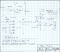
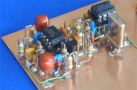
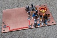
Got my own idea, thanks for the info. though. Gonna go with Manhattan style soldering too I think, at least part of the board. Here is the scematic I made, not sure if its finished. I will update the values or at least narrow them down when Im done.
Manhattan style soldering example: Not mine
ZakWolf, Tue Mar 08 2016, 01:16AM
woodchuck wrote ...
Claude wrote ...
Sorry,this is the updated schematic that I used. You don't have to use the audio modulation if you don't want to.
Claude.

Don't know German but the schematic seems to indicate that the secondary is 5cm in diameter and a mere 7.5 cm long. With these diminutive dimensions and a 4MHz operating frequency, what sort of brush/spark discharge does it produce? Sorry,this is the updated schematic that I used. You don't have to use the audio modulation if you don't want to.
Claude.

Got my own idea, thanks for the info. though. Gonna go with Manhattan style soldering too I think, at least part of the board. Here is the scematic I made, not sure if its finished. I will update the values or at least narrow them down when Im done.

Manhattan style soldering example: Not mine


Print this page
