
EMP BOX - TEST RESULTS - CALCULATOR AND LED CONNECTED TO A COIL...
Slava, Wed Nov 11 2015, 03:48PMMore results are in! ...

check out videos on page

I tested 3 designs... I am torn between two of them...
One of them can light an LED farther and resets a calculator, the other puts random digits on a calculator... but the LED range is less...
Any thoughts?

Re: EMP BOX - TEST RESULTS - CALCULATOR AND LED CONNECTED TO A COIL...
hen918, Wed Nov 11 2015, 06:39PM
Try adjusting the length of the spark gap and post results.
Thanks
hen918, Wed Nov 11 2015, 06:39PM
Try adjusting the length of the spark gap and post results.
Thanks
Re: EMP BOX - TEST RESULTS - CALCULATOR AND LED CONNECTED TO A COIL...
Slava, Wed Nov 11 2015, 07:00PM
I made an error, .. the coil diameters are different.
10 TURN = 5.5cm coil form
5 TURN= 8.0cm coil form

In this test I used coils with the same diameter. Got different results. My power supply is running off of batteries, so try not to compare new results to old ones.
Slava, Wed Nov 11 2015, 07:00PM
I made an error, .. the coil diameters are different.
10 TURN = 5.5cm coil form
5 TURN= 8.0cm coil form

In this test I used coils with the same diameter. Got different results. My power supply is running off of batteries, so try not to compare new results to old ones.
Re: EMP BOX - TEST RESULTS - CALCULATOR AND LED CONNECTED TO A COIL...
Sulaiman, Wed Nov 11 2015, 08:30PM
NICE PROJECT
try a better spark gap, 'pointy' spark gap electrodes are (in my opinion) rubbish compared to large radius electrodes
(e.g. the back of two metal spoons or any curved objects), the gap will need to be MUCH smaller.
I suspect that for a given power supply / supply of power
the greatest range will be achieved by fewer but larger energy 'pulses' per second rather than many small ones
that means more capacitance and/or voltage ( E = 0.5 x C x V^2 )
The number of turns and diameter of the coil will have multiple effects;
. larger coils transmit farther
. fewer turns decreases 'Q' and increase frequency and peak current, stressing the spark gap, capacitors and wire more
. higher frequencies are likely to induce more interference than lower frequencies (use higher voltage / lower capacitance)
Having transmit and receive coils in the same plane as in your video has sometimes worked better for me than axially
circular coils tend to have a uniform field, square coils may work better in this case.
also, having a 'spare' high voltage generator and capacitors helps ;)
Re: EMP BOX - TEST RESULTS - CALCULATOR AND LED CONNECTED TO A COIL...
Slava, Wed Nov 11 2015, 08:38PM
Thanks for the tip. Right now I'm using screws as the gap... I redid my web page btw..

I need to figure out what setup is best... I'm surprised it works with other power supplies...
I built an EMP box long time ago and it turned out that the spark gap and resonant LC didn't do anything, all the RF came right from the power supply. I hate this because I have no control over it.
With this setup I tried different power supplies and it worked with all of them.
Slava, Wed Nov 11 2015, 08:38PM
Thanks for the tip. Right now I'm using screws as the gap... I redid my web page btw..

I need to figure out what setup is best... I'm surprised it works with other power supplies...
I built an EMP box long time ago and it turned out that the spark gap and resonant LC didn't do anything, all the RF came right from the power supply. I hate this because I have no control over it.
With this setup I tried different power supplies and it worked with all of them.
Re: EMP BOX - TEST RESULTS - CALCULATOR AND LED CONNECTED TO A COIL...
Signification, Thu Nov 12 2015, 02:10PM
IIRC, I got best results on an old coil coupling experiment that used a stationary round coil with a square coil as the distant "fine tune" element. I even used the degauss coil from a TV with some success (remove the "varistor" ??). I didn't try variation of the winding turns or caps (should have) then--just alignment effects for what I had.
Better be "careful" here...
Re: EMP BOX - TEST RESULTS - CALCULATOR AND LED CONNECTED TO A COIL...
Slava, Thu Nov 12 2015, 04:15PM
When I get home from class, I want to try a 20 turn coil...
Slava, Thu Nov 12 2015, 04:15PM
When I get home from class, I want to try a 20 turn coil...
Re: EMP BOX - TEST RESULTS - CALCULATOR AND LED CONNECTED TO A COIL...
Signification, Thu Nov 12 2015, 04:45PM
I have more comments in mind, but it seems if you waited a bit longer between posts, you, I, and others, could get more information per post which will benefit all, do you plan on trying square or rectangular coil combinations, perhaps of certain dimensional ratios
...more later...
Signification, Thu Nov 12 2015, 04:45PM
Slava wrote ...
When I get home from class, I want to try a 20 turn coil...
When I get home from class, I want to try a 20 turn coil...
I have more comments in mind, but it seems if you waited a bit longer between posts, you, I, and others, could get more information per post which will benefit all, do you plan on trying square or rectangular coil combinations, perhaps of certain dimensional ratios
...more later...
Re: EMP BOX - TEST RESULTS - CALCULATOR AND LED CONNECTED TO A COIL...
Slava, Thu Nov 12 2015, 06:44PM
Just tested, 3 turn coil and 20 turn coil...


Two inaccuracies in my test...
1) hard to tell when the led turned off
2) long alagator clips may throw off readings for low number of turns
Slava, Thu Nov 12 2015, 06:44PM
Just tested, 3 turn coil and 20 turn coil...


Two inaccuracies in my test...
1) hard to tell when the led turned off
2) long alagator clips may throw off readings for low number of turns
Re: EMP BOX - TEST RESULTS - CALCULATOR AND LED CONNECTED TO A COIL...
Signification, Thu Nov 12 2015, 07:31PM
There's a maxima. An LC circuit can be represented mathematically. Simple differentiation can find the maxima patterns.
Can you fire a single pulse and capture it on a scope? You're looking for the maximum peak of an exponentially decaying sinusoidal...for starters...
Re: EMP BOX - TEST RESULTS - CALCULATOR AND LED CONNECTED TO A COIL...
Slava, Thu Nov 12 2015, 07:34PM
I dont have a scope. .. can you try it?
I wish i could test for capacitor value too, but that would requre too many experiments.
Slava, Thu Nov 12 2015, 07:34PM
I dont have a scope. .. can you try it?
I wish i could test for capacitor value too, but that would requre too many experiments.
Re: EMP BOX - TEST RESULTS - CALCULATOR AND LED CONNECTED TO A COIL...
Signification, Thu Nov 12 2015, 08:01PM
I was a bit brief. What really needs to be measured is the frequency of the LC circuit. It can either be calculated--not very accurate in the real world, OR the time between zero-crossings measured and frequency derived from that: f=1/t.
Signification, Thu Nov 12 2015, 08:01PM
I was a bit brief. What really needs to be measured is the frequency of the LC circuit. It can either be calculated--not very accurate in the real world, OR the time between zero-crossings measured and frequency derived from that: f=1/t.
Re: EMP BOX - TEST RESULTS - CALCULATOR AND LED CONNECTED TO A COIL...
Slava, Thu Nov 12 2015, 09:08PM
With a 10 turn coil, i got 12mH inductance, capacitor is about 1800pF ...
~35kHz
Found some flaws in my experiment...
1) It was hard to tell when the LED turned off
2) I used alligator clips that had long wires, this will throw off the data when working with low turn number of coil...
!UPDATE!
I remeasured everything using direct wire connections instead of alligator clips...

Re: EMP BOX - TEST RESULTS - CALCULATOR AND LED CONNECTED TO A COIL...
Signification, Sat Nov 14 2015, 04:57PM
Did you get the 35kHz by measurement or calculation? Also did this resonant value vary when you changed your measurement connections?
Signification, Sat Nov 14 2015, 04:57PM
Did you get the 35kHz by measurement or calculation? Also did this resonant value vary when you changed your measurement connections?
Re: EMP BOX - TEST RESULTS - CALCULATOR AND LED CONNECTED TO A COIL...
Slava, Sat Nov 14 2015, 05:24PM
I used a online calculator to find resonance... How can I optimize capacitance too? I used a value that someone on youtube used... Each capacitor value will require about 40 experiments to get data ...
...
Slava, Sat Nov 14 2015, 05:24PM
I used a online calculator to find resonance... How can I optimize capacitance too? I used a value that someone on youtube used... Each capacitor value will require about 40 experiments to get data
 ...
...Re: EMP BOX - TEST RESULTS - CALCULATOR AND LED CONNECTED TO A COIL...
hen918, Sat Nov 14 2015, 10:51PM
I don't think there is any way that coil could be 12mH.
12uH perhaps?
hen918, Sat Nov 14 2015, 10:51PM
I don't think there is any way that coil could be 12mH.
12uH perhaps?
Re: EMP BOX - TEST RESULTS - CALCULATOR AND LED CONNECTED TO A COIL...
Slava, Sat Nov 14 2015, 11:02PM
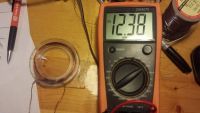
See attached photo..
edit:
... You might be right... I just used an internet inductance calculator...
16.2uH ... I think it's actually 12uH ... I put the wrong diameter into the calculator
edit 2:
Just did it again with the right values... got 13.1uH

DIAM: 0.055
LENGTH: 0.003 meters
TURNS: 10
Slava, Sat Nov 14 2015, 11:02PM
See attached photo..

edit:
... You might be right... I just used an internet inductance calculator...
16.2uH ... I think it's actually 12uH ... I put the wrong diameter into the calculator
edit 2:
Just did it again with the right values... got 13.1uH

DIAM: 0.055
LENGTH: 0.003 meters
TURNS: 10
Re: EMP BOX - TEST RESULTS - CALCULATOR AND LED CONNECTED TO A COIL...
Signification, Sat Nov 14 2015, 11:22PM
WOW--is that meter right?? My thought..."I wish I could get that kind of L in air-core coils" Maybe the "low batt" is having an effect. can you give a good value of the diameter of the coil and exactly how many turns on the coil connected to the meter--that would help. It is air-core for sure, right?
The formula for the frequency of an LC resonance circuit is f(Hz)=1/[2*pi sqrt(LC)]. Can you solve this formula for, say, "L" by hand--We are so dependent on machines now.
edit: Just had a thought--your meter could be broken, or simply putting "mH" for "uH" Do you have a second way to measure this coil OR a coil of KNOWN "mH's"?
Re: EMP BOX - TEST RESULTS - CALCULATOR AND LED CONNECTED TO A COIL...
Slava, Sat Nov 14 2015, 11:25PM
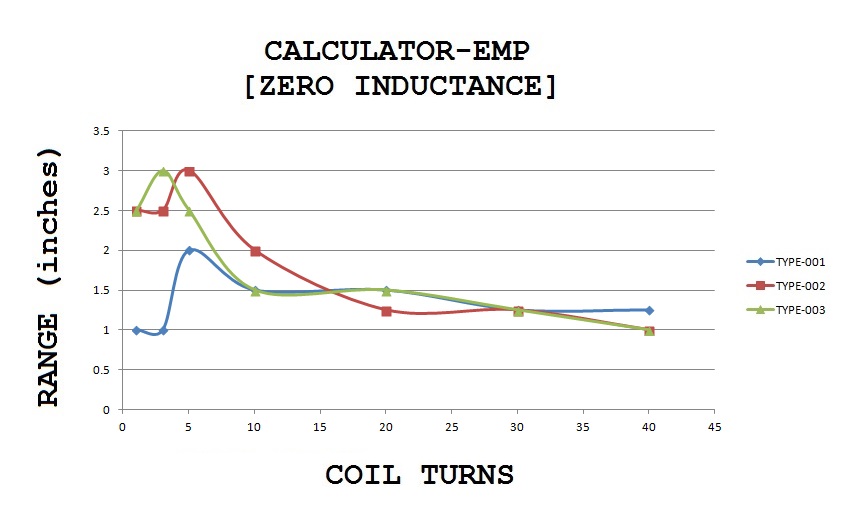
Here I posted all the data, including coil parameters..

Knowing the inductance value isn't important to me, my tests are based on empirical data. Distance at calculator rest/scramble, using different coils. When I did my second test, I tried to use direct connections instead of using long wires. This made data for low turn coils more accurate. I also used the same coil diameter for all the coils, only varying the number of turns. Ignore the first set of data.
Slava, Sat Nov 14 2015, 11:25PM
Signification wrote ...
WOW--is that meter right?? My thought..."I wish I could get that kind of L in air-core coils" Maybe the "low batt" is having an effect. can you give a good value of the diameter of the coil and exactly how many turns on the coil connected to the meter--that would help. It is air-core for sure, right?
The formula for the frequency of an LC resonance circuit is f(Hz)=1/[2*pi sqrt(LC)]. Can you solve this formula for, say, "L" by hand--We are so dependent on machines now.
Here I posted all the data, including coil parameters..

Knowing the inductance value isn't important to me, my tests are based on empirical data. Distance at calculator rest/scramble, using different coils. When I did my second test, I tried to use direct connections instead of using long wires. This made data for low turn coils more accurate. I also used the same coil diameter for all the coils, only varying the number of turns. Ignore the first set of data.
Re: EMP BOX - TEST RESULTS - CALCULATOR AND LED CONNECTED TO A COIL...
Signification, Sat Nov 14 2015, 11:33PM
I am very familiar with the false HIGH VOLTAGE claims of those ebay modules--I just saw a module rated at 1,000,000 V today! it's like the outrageous claims on the stun gun's millions of voltages--I guess a way to measure it yourself must be found to know what is going on--also the output waveform is strange.
--seems we were writing replies simultaneously here!
Re: EMP BOX - TEST RESULTS - CALCULATOR AND LED CONNECTED TO A COIL...
Slava, Sat Nov 14 2015, 11:37PM
I measured mine and it turned out to be 9kV @ 6VDC input... not sure how accurate my meter is though (i made it by hand)
I bought a 250uA galvenometer with a range from 1 to 10... so i assumed 10 @ 250uA ... then I calculated what resistor I need for it.
(10kV @ 250uA)
edit:
I just sketched up up the components in a CAD program... I need help making a box for them...

edit 2:
this would make a nice chassis, but there is no room for parts... Maybe I can add a PVC pipe extension?

Slava, Sat Nov 14 2015, 11:37PM
Signification wrote ...
I am very familiar with the false HIGH VOLTAGE claims of those ebay modules--I just saw a module rated at 1,000,000 V today! it's like the outrageous claims on the stun gun's millions of voltages--I guess a way to measure it yourself must be found to know what is going on--also the output waveform is strange.
--seems we were writing replies simultaneously here!
I measured mine and it turned out to be 9kV @ 6VDC input... not sure how accurate my meter is though (i made it by hand)
I bought a 250uA galvenometer with a range from 1 to 10... so i assumed 10 @ 250uA ... then I calculated what resistor I need for it.
(10kV @ 250uA)
edit:
I just sketched up up the components in a CAD program... I need help making a box for them...

edit 2:
this would make a nice chassis, but there is no room for parts... Maybe I can add a PVC pipe extension?

Re: EMP BOX - TEST RESULTS - CALCULATOR AND LED CONNECTED TO A COIL...
Slava, Mon Nov 16 2015, 05:42PM
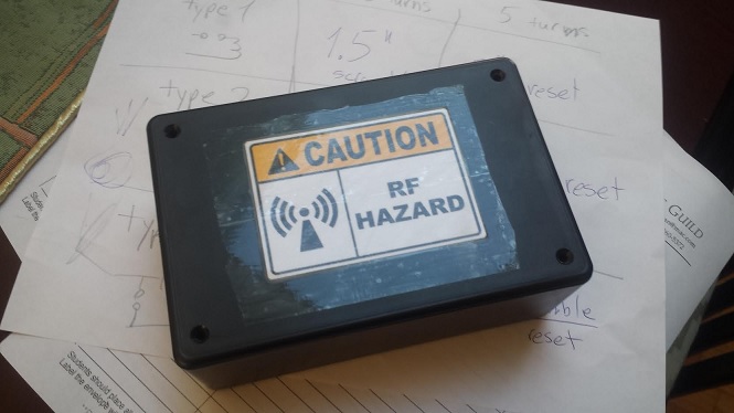
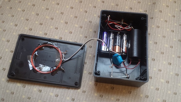
PROTOTYPE #001 is complete!
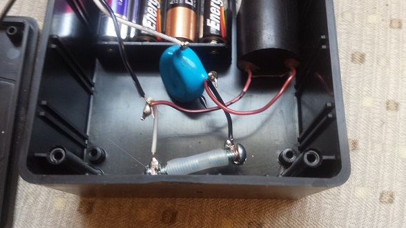
persion.info/projects/emp-box/SPARK-GAP-001- edited.mp4
Slava, Mon Nov 16 2015, 05:42PM
PROTOTYPE #001 is complete!


persion.info/projects/emp-box/SPARK-GAP-001- edited.mp4
Re: EMP BOX - TEST RESULTS - CALCULATOR AND LED CONNECTED TO A COIL...
hen918, Mon Nov 16 2015, 09:32PM
That tubing over the spark gap in your last photo looks like a fire hazard
hen918, Mon Nov 16 2015, 09:32PM
That tubing over the spark gap in your last photo looks like a fire hazard
Re: EMP BOX - TEST RESULTS - CALCULATOR AND LED CONNECTED TO A COIL...
Slava, Tue Nov 17 2015, 12:13AM
Working on prototype 003...
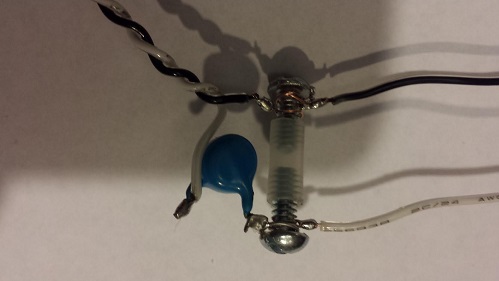
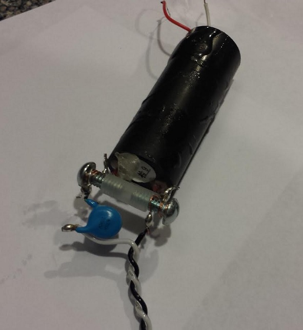
Waiting for power supply to come. The aim in this one is to minimize form factor.
P.S. The arc isn't hot enough to burn plastic tubing.
Can anyone help figure out the ideal form factor? I was thinking of using a 6V flashlight, the coil would go on it nicely, however, not enough room for the HV power source.
Slava, Tue Nov 17 2015, 12:13AM
Working on prototype 003...


Waiting for power supply to come. The aim in this one is to minimize form factor.
P.S. The arc isn't hot enough to burn plastic tubing.
Can anyone help figure out the ideal form factor? I was thinking of using a 6V flashlight, the coil would go on it nicely, however, not enough room for the HV power source.
Re: EMP BOX - TEST RESULTS - CALCULATOR AND LED CONNECTED TO A COIL...
Signification, Tue Nov 17 2015, 04:48PM
I would think twice about that spark being "safe" esp. over time. I have used those modules and they are bright and hot, even without the LC--there may be an internal "C" right at the output?? Do you know the makeup oh the high voltage module? I have tried long and hard to find the schema--I started on the 7kV modules.
Why not just use two air core -elevated- screws for the gap? JB weld will help with the details.
Even if the spark doesn't quickly burn the plastic it will over time.
Re: EMP BOX - TEST RESULTS - CALCULATOR AND LED CONNECTED TO A COIL...
Slava, Tue Nov 17 2015, 04:58PM
I would only be concerned if the spark was orange. Mine is thin and white/blue...
Slava, Tue Nov 17 2015, 04:58PM
I would only be concerned if the spark was orange. Mine is thin and white/blue...
Re: EMP BOX - TEST RESULTS - CALCULATOR AND LED CONNECTED TO A COIL...
2Spoons, Tue Nov 17 2015, 09:32PM
What sort of plastic is it? Because it needs to resist ozone, nitric oxides and hard UV.
2Spoons, Tue Nov 17 2015, 09:32PM
What sort of plastic is it? Because it needs to resist ozone, nitric oxides and hard UV.
Re: EMP BOX - TEST RESULTS - CALCULATOR AND LED CONNECTED TO A COIL...
Signification, Tue Nov 17 2015, 09:43PM
...gonna change his data quickly over time too...
Signification, Tue Nov 17 2015, 09:43PM
...gonna change his data quickly over time too...
Re: EMP BOX - TEST RESULTS - CALCULATOR AND LED CONNECTED TO A COIL...
Slava, Tue Nov 17 2015, 10:00PM
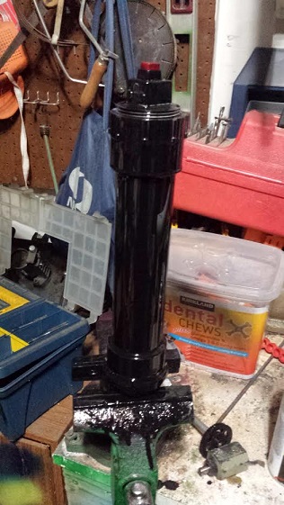
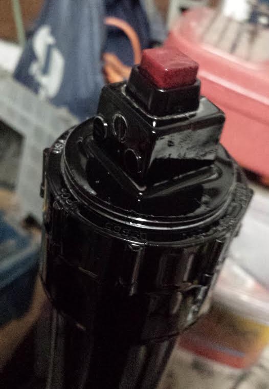
P.S. ... I don't change my data, I post new data and leave the old there. I also describe anything that might throw it off.... prototype #3 i changed the capacitor value, but I posted about that too... I tried 5 turns with type 3 EMP with different capacitors and got the same range...
LOL... I accidentally electrocuted myself in the mouth today with 9kV, lol
Slava, Tue Nov 17 2015, 10:00PM


P.S. ... I don't change my data, I post new data and leave the old there. I also describe anything that might throw it off.... prototype #3 i changed the capacitor value, but I posted about that too... I tried 5 turns with type 3 EMP with different capacitors and got the same range...
LOL... I accidentally electrocuted myself in the mouth today with 9kV, lol
Re: EMP BOX - TEST RESULTS - CALCULATOR AND LED CONNECTED TO A COIL...
Signification, Wed Nov 18 2015, 02:26AM
"Electrocute" usually implies 'killed'
You can see a beautiful picture of the resonant frequency of the oscillation of any particular LC by energizing or DE-energizing the cap through the coil while hooked to an o'scope. As the amplitude drops, the frequency (resonant) remains constant on the scope and you can simply read the LC frequency or period.
BTW...an interesting experiment: Charge a disposable camera until the orange "ready" Ne lamp comes on, then zap it with your device--I bet it fires the strobe! May even work on a digital camera--if you have one to trash. My small laser flashlamp trigger fires them at a few inches.
You know this device would surely be illegal (if not already) if boosted!
Re: EMP BOX - TEST RESULTS - CALCULATOR AND LED CONNECTED TO A COIL...
Slava, Wed Nov 18 2015, 02:30AM
I read that it is ok to own one, but not to sell it or carry it around.
Slava, Wed Nov 18 2015, 02:30AM
Signification wrote ...
"Electrocute" usually implies 'killed'
You can see a beautiful picture of the resonant frequency of the oscillation of any particular LC by energizing or DE-energizing the cap through the coil while hooked to an o'scope. As the amplitude drops, the frequency (resonant) remains constant on the scope and you can simply read the LC frequency or period.
BTW...an interesting experiment: Charge a disposable camera until the orange "ready" Ne lamp comes on, then zap it with your device--I bet it fires the strobe! May even work on a digital camera--if you have one to trash. My small laser flashlamp trigger fires them at a few inches.
You know this device would surely be illegal (if not already) if boosted!
I read that it is ok to own one, but not to sell it or carry it around.


Re: EMP BOX - TEST RESULTS - CALCULATOR AND LED CONNECTED TO A COIL...
GrantX, Wed Nov 18 2015, 04:13PM
I think what Signification meant is that the spark-gap will degrade over time, and you will see a noticeable change in performance. The screw electrodes will slowly be eroded and soot will gather in the gap (along with the plastic being hit by UV). I imagine that over time the threshold voltage will drop and the quench time will increase, damaging performance.
A long time ago I lashed together something similar as a wireless power demo (LEDs with a coil as the receiver). I first used a few gas discharge tubes in series (surge arresters, not meant for high duty cycle stuff), which degraded very rapidly, even at very low powers. After that I tried a spark gap made from two brass bolts on a phenolic board, which was good enough for my purposes. The spark was quite close to the board, so it required periodic cleaning to avoid carbon tracks from forming and eventually became discolored from the UV/heat. However I never noticed much degradation in performance, so you might see some good results by using a slightly larger brass/copper gap with some ventilation.
GrantX, Wed Nov 18 2015, 04:13PM
Signification wrote ...
...gonna change his data quickly over time too...
...gonna change his data quickly over time too...
I think what Signification meant is that the spark-gap will degrade over time, and you will see a noticeable change in performance. The screw electrodes will slowly be eroded and soot will gather in the gap (along with the plastic being hit by UV). I imagine that over time the threshold voltage will drop and the quench time will increase, damaging performance.
A long time ago I lashed together something similar as a wireless power demo (LEDs with a coil as the receiver). I first used a few gas discharge tubes in series (surge arresters, not meant for high duty cycle stuff), which degraded very rapidly, even at very low powers. After that I tried a spark gap made from two brass bolts on a phenolic board, which was good enough for my purposes. The spark was quite close to the board, so it required periodic cleaning to avoid carbon tracks from forming and eventually became discolored from the UV/heat. However I never noticed much degradation in performance, so you might see some good results by using a slightly larger brass/copper gap with some ventilation.
Re: EMP BOX - TEST RESULTS - CALCULATOR AND LED CONNECTED TO A COIL...
Slava, Wed Nov 18 2015, 04:19PM
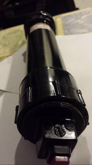
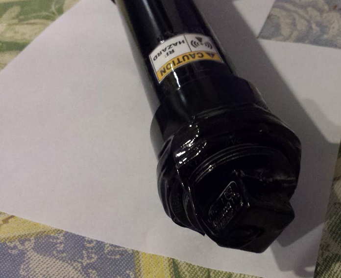
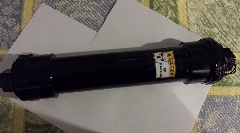
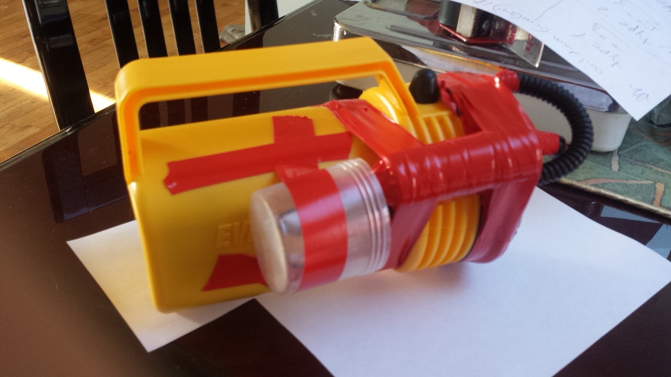
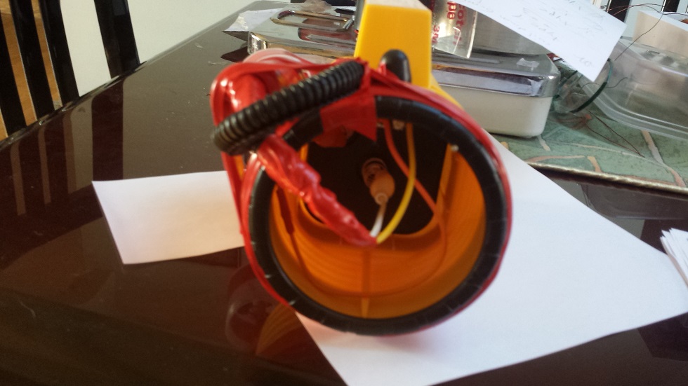
EMP version 4 ....
I will use this flashlight as a chassis...

Slava, Wed Nov 18 2015, 04:19PM
EMP version 4 ....
I will use this flashlight as a chassis...

Re: EMP BOX - TEST RESULTS - CALCULATOR AND LED CONNECTED TO A COIL...
Sulaiman, Wed Nov 18 2015, 08:11PM
regarding the plastic tubing spark gap, it will be interesting to see which is first
melting due to heat, disintegrating due to ozone, surface tracking then carbonisation then fire .... (add your guess here)
I'm sure that it will work, for a while ;)
P.S. I bought a couple of 4-cells-in-series battery holders for some of my many 18650 lithium cells, ex-laptop battery packs.
After a little tweaking, very useful, 1A=good, 2A = a little warm but no problem, 5A peaks ok. (14,28,70 Watts per pack)
and voltage usable by most '12 Vdc' circuits.
I also have some 're-wrapped' & 're-specified' (x2) mAh, very few failures and good value even though the mAh is 'optimistic' ;)
and I do not feel as guilty by not using lead-acid batteries.
Re: EMP BOX - TEST RESULTS - CALCULATOR AND LED CONNECTED TO A COIL...
Slava, Wed Nov 18 2015, 08:53PM
When i get more power supplies i will do a stress test on a spark gap
edit >>>
You guys were right... I ran the spark gap for 4 minutes and it started to melt the plastic sleeve. The gap did not fail though. Even with a melted sleeve the gap distance stayed the same and there was no fire.

Re: EMP BOX - TEST RESULTS - CALCULATOR AND LED CONNECTED TO A COIL...
Slava, Sat Nov 21 2015, 08:19PM
Video:
Slava, Sat Nov 21 2015, 08:19PM


Video:

Re: EMP BOX - TEST RESULTS - CALCULATOR AND LED CONNECTED TO A COIL...
2Spoons, Sun Nov 22 2015, 10:37PM
why not use an ordinary automotive sparkplug for your spark gap?
2Spoons, Sun Nov 22 2015, 10:37PM
why not use an ordinary automotive sparkplug for your spark gap?
Re: EMP BOX - TEST RESULTS - CALCULATOR AND LED CONNECTED TO A COIL...
Slava, Sun Nov 22 2015, 10:40PM
Some of them have internal resistors... I don't know which to get, they are also a bit large... Can you regap it to 3mm ?
Slava, Sun Nov 22 2015, 10:40PM
2Spoons wrote ...
why not use an ordinary automotive sparkplug for your spark gap?
why not use an ordinary automotive sparkplug for your spark gap?
Some of them have internal resistors... I don't know which to get, they are also a bit large... Can you regap it to 3mm ?
Re: EMP BOX - TEST RESULTS - CALCULATOR AND LED CONNECTED TO A COIL...
GrantX, Mon Nov 23 2015, 04:34AM
Where I live, you can buy small sparkplugs designed for lawnmowers from almost every petrol station and hardware store. They are a bit smaller than car sparkplugs, and have zero internal resistance. The gap distance is easily adjustable by lifting the electrode up with a screwdriver. I imagine they will withstand a lot more power for longer when compared to the plastic tubing gap.
Re: EMP BOX - TEST RESULTS - CALCULATOR AND LED CONNECTED TO A COIL...
Signification, Sun Dec 27 2015, 01:22PM
Is there a simple way of a way adding a tiny antenna to the EMP generator for a kind of weak directional beam (I think it would be similar to those ion-gun gadgets, but I want something much simpler with only a range of a few inches). I would like to trigger a triggered spark gap without an actual physical connection to the center trigger terminal.
Print this page