
At the assembly stage. Looking for feedback (no pun intended)
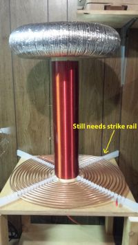
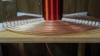
crashstudio, Tue Jun 09 2015, 02:00AMHere it is. I've completed all the components and have begun assembly. Any feedback is greatly appreciated at this stage. I really just want to be sure I'm on the right track.
All pics are below including the schematic I'm following. I'm assuming the safest bet is to ground the NST to RF, not house. Also, before you warn me I am going to install a strike rail.
The NST is 15kv 60ma
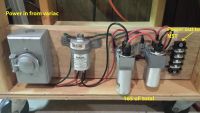
The A/C filter circuit consists of an RFI EMI Tesla Filter 15 Amp's 115/250vac and 2 PFC caps from microwaves in parallel totaling 165uF. TeslaMap suggests 165uF for optimum PFC.
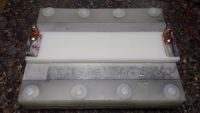
Capacitor measures 10.9nF - resonant cap for this NST is 10.6 (at the time I didn't know an LTR was better or I would have added more plates). It's constructed with 30 sheets of 8 X 10 polyethylene windows and 28 sheets of aluminum foil.
It will soon be replaced with an LTR MMC. I've already ordered 40 0.15uF, 2kV 942C20P15K-F caps and will be assembling 2 strings of 17 for a total of just over 17nF.
Toroid is 4" aluminum ducting with aluminum tape wrapped all around it and 8.5" pie pans bolted in the center. When I entered it's dimensions in TeslaMap it said the capacitance is 18.3pF

Re: At the assembly stage. Looking for feedback (no pun intended)
Blackcurrant, Tue Jun 09 2015, 11:50AM
A few things I would look out for
Keep all the HV parts smooth, so there's less likely to be any unwanted break out
you may want to put some plastic between coils, it might flash over near the bottom part
make sure the tunings ok take your time over this bit
put a sharp breakout point on the top so you know were it should be sparking from
If there's any small fires turn it off quick :)
Re: At the assembly stage. Looking for feedback (no pun intended)
Graham Armitage, Tue Jun 09 2015, 12:07PM
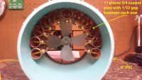
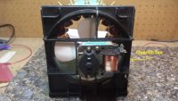
This build looks good. Nice construction too. I love the NST protection features - you will be happy you have those in place. I learned the hard way With regards to the ground, I always grounded the secondary to a dedicated RF ground, but kept he NST grounded to the house ground. I would worry about ground loops, but I am no expert. One of the best spark gaps I ever built was a forced air quenched gap. It worked really well. Fast quenching really helps. That said, I wonder if the length of copper tubing will allow the primary spark to travel along its length for too long before being extinguished? How do you adjust the spark gap for max voltage?
Graham Armitage, Tue Jun 09 2015, 12:07PM
This build looks good. Nice construction too. I love the NST protection features - you will be happy you have those in place. I learned the hard way
 With regards to the ground, I always grounded the secondary to a dedicated RF ground, but kept he NST grounded to the house ground. I would worry about ground loops, but I am no expert. One of the best spark gaps I ever built was a forced air quenched gap. It worked really well. Fast quenching really helps. That said, I wonder if the length of copper tubing will allow the primary spark to travel along its length for too long before being extinguished? How do you adjust the spark gap for max voltage?
Re: At the assembly stage. Looking for feedback (no pun intended)
crashstudio, Tue Jun 09 2015, 10:09PM
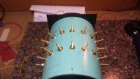
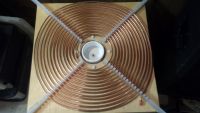
Each copper pipe is 4 1/4" long. I got the design from youtube and the guy showed it in action in a later video, seemed to work great. The gap between each one is 1/32", I got that from a couple different coilers. As far as adjusting the gap, I can change it but it would take a good amount of time so I'm just hoping it will work the way it is. Some day I'm going to design one that can be adjusted by turning a screw.
As far as the NST grounding I had the same concern, you're probably right. I'll just change it to mains ground. Thank you, and thanks for the compliment.
crashstudio, Tue Jun 09 2015, 10:09PM
Graham Armitage wrote ...
This build looks good. Nice construction too. I love the NST protection features - you will be happy you have those in place. I learned the hard way With regards to the ground, I always grounded the secondary to a dedicated RF ground, but kept he NST grounded to the house ground. I would worry about ground loops, but I am no expert. One of the best spark gaps I ever built was a forced air quenched gap. It worked really well. Fast quenching really helps. That said, I wonder if the length of copper tubing will allow the primary spark to travel along its length for too long before being extinguished? How do you adjust the spark gap for max voltage?
This build looks good. Nice construction too. I love the NST protection features - you will be happy you have those in place. I learned the hard way
 With regards to the ground, I always grounded the secondary to a dedicated RF ground, but kept he NST grounded to the house ground. I would worry about ground loops, but I am no expert. One of the best spark gaps I ever built was a forced air quenched gap. It worked really well. Fast quenching really helps. That said, I wonder if the length of copper tubing will allow the primary spark to travel along its length for too long before being extinguished? How do you adjust the spark gap for max voltage?
 Each copper pipe is 4 1/4" long. I got the design from youtube and the guy showed it in action in a later video, seemed to work great. The gap between each one is 1/32", I got that from a couple different coilers. As far as adjusting the gap, I can change it but it would take a good amount of time so I'm just hoping it will work the way it is. Some day I'm going to design one that can be adjusted by turning a screw.
As far as the NST grounding I had the same concern, you're probably right. I'll just change it to mains ground. Thank you, and thanks for the compliment.
Re: At the assembly stage. Looking for feedback (no pun intended)
crashstudio, Tue Jun 09 2015, 10:13PM
Thanks. You mean plastic between the bottom of the secondary and primary right?
crashstudio, Tue Jun 09 2015, 10:13PM
Blackcurrant wrote ...
A few things I would look out for
Keep all the HV parts smooth, so there's less likely to be any unwanted break out
you may want to put some plastic between coils, it might flash over near the bottom part
make sure the tunings ok take your time over this bit
put a sharp breakout point on the top so you know were it should be sparking from
If there's any small fires turn it off quick :)
Thanks. You mean plastic between the bottom of the secondary and primary right?
Re: At the assembly stage. Looking for feedback (no pun intended)
Hazmatt_(The Underdog), Wed Jun 10 2015, 03:50AM
Why so much primary?
You should have 5-10 turns of primary and that's it.
Find the resonant freq. of your system at turn 5-7, and adjust your secondary accordingly.
Remember, every excess inch of primary, AND HOOKUP is LOSS.
Hazmatt_(The Underdog), Wed Jun 10 2015, 03:50AM
Why so much primary?
You should have 5-10 turns of primary and that's it.
Find the resonant freq. of your system at turn 5-7, and adjust your secondary accordingly.
Remember, every excess inch of primary, AND HOOKUP is LOSS.
Re: At the assembly stage. Looking for feedback (no pun intended)
Blackcurrant, Wed Jun 10 2015, 07:05PM
yes, like a plastic tube to stop it jumping from the inner primary coil to the secondary. It might not happen but it does look close to me.
If your gap fails to fire, try a re-tune or link out one of the gaps.
Have you thought of a safe way to discharge the caps? If something fails there could still be charge in them, trust nothing!
Also the secondary coil may hold a bit of static after use
it'll be fun, good luck
Re: At the assembly stage. Looking for feedback (no pun intended)
Dr. H., Wed Jun 10 2015, 07:56PM
Hi there,
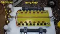
I am a bit worried about the terry filter -did you remove the unnecessary copper pads from the board ? On some of those boards the distance between them is really small (for easier soldering) and might flash over.
Cheers
Dr. H., Wed Jun 10 2015, 07:56PM
Hi there,
I am a bit worried about the terry filter -did you remove the unnecessary copper pads from the board ? On some of those boards the distance between them is really small (for easier soldering) and might flash over.
Cheers

Re: At the assembly stage. Looking for feedback (no pun intended)
crashstudio, Thu Jun 11 2015, 02:52AM
Dr. H... the board is blank. It was made primarily for a Terry filter. In this pic its not even complete. I'll post a new one
crashstudio, Thu Jun 11 2015, 02:52AM
Dr. H... the board is blank. It was made primarily for a Terry filter. In this pic its not even complete. I'll post a new one
Re: At the assembly stage. Looking for feedback (no pun intended)
Hazmatt_(The Underdog), Thu Jun 11 2015, 02:53AM
Some of the Vero-board is completely copperless, and this one looks to be that.
I'm a bit concerned about your 630V caps, I think they're going to die.
You might want to try to run your filter with some high voltage for a short while, turn off, and see if the caps are hot.
Re: At the assembly stage. Looking for feedback (no pun intended)
crashstudio, Thu Jun 11 2015, 03:00AM
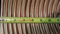
I followed the same design specs as many others with my power supply and TeslaMap has the primary at 82.9uH tapped at turn 14 -15
crashstudio, Thu Jun 11 2015, 03:00AM
Hazmatt_(The Underdog) wrote ...
Why so much primary?
You should have 5-10 turns of primary and that's it.
Find the resonant freq. of your system at turn 5-7, and adjust your secondary accordingly.
Remember, every excess inch of primary, AND HOOKUP is LOSS.
Why so much primary?
You should have 5-10 turns of primary and that's it.
Find the resonant freq. of your system at turn 5-7, and adjust your secondary accordingly.
Remember, every excess inch of primary, AND HOOKUP is LOSS.
I followed the same design specs as many others with my power supply and TeslaMap has the primary at 82.9uH tapped at turn 14 -15
Re: At the assembly stage. Looking for feedback (no pun intended)
Hazmatt_(The Underdog), Fri Jun 12 2015, 01:00AM
I used to follow what everyone else said too, until I realized I could get better results by leading in my own way and doing my own thing.
After this base is done, I will match the secondary to the primary, "by working backward", I get better performance that way.
Matt

Re: At the assembly stage. Looking for feedback (no pun intended)
crashstudio, Fri Jun 12 2015, 04:00AM
crashstudio, Fri Jun 12 2015, 04:00AM
Hazmatt_(The Underdog) wrote ...
I used to follow what everyone else said too, until I realized I could get better results by leading in my own way and doing my own thing.
After this base is done, I will match the secondary to the primary, "by working backward", I get better performance that way.
Matt

Well I "learn" backwards. I always start at the top and work my way down. Been learning like this sense I was a kid. Now I want to learn about Tesla Coils so I'm building one and will learn the rest as I go. I'm very intrigued by your design. I'm trying to understand how the inductance and resonance will work with so little turns and so much spacing. I would really appreciate if you could explain, it will help me learn. I for one have never been much for following anyone's lead either unless it was necessary so, like you, I will eventually break off into my own designs.
Also the caps you're concerned about are 2100v microwave oven caps and it's just the A/C conditioner for the low voltage side of the NST. TeslaMap suggests 166uF for PFC and those 2 in parallel read 165uF on my meter.
I used to follow what everyone else said too, until I realized I could get better results by leading in my own way and doing my own thing.
After this base is done, I will match the secondary to the primary, "by working backward", I get better performance that way.
Matt

Well I "learn" backwards. I always start at the top and work my way down. Been learning like this sense I was a kid. Now I want to learn about Tesla Coils so I'm building one and will learn the rest as I go. I'm very intrigued by your design. I'm trying to understand how the inductance and resonance will work with so little turns and so much spacing. I would really appreciate if you could explain, it will help me learn. I for one have never been much for following anyone's lead either unless it was necessary so, like you, I will eventually break off into my own designs.
Also the caps you're concerned about are 2100v microwave oven caps and it's just the A/C conditioner for the low voltage side of the NST. TeslaMap suggests 166uF for PFC and those 2 in parallel read 165uF on my meter.
Re: At the assembly stage. Looking for feedback (no pun intended)
Hazmatt_(The Underdog), Fri Jun 12 2015, 04:14AM
The little red caps on your filter are rated for 2100V? Wow!
With the spacing, the tank inductance will work just fine. It's the combination of L and C, as you already know, that does the trick.
I've got it all matched for the 15/60 NST, I just have to figure out what the Fo is. If it's real low because Lpri is low, I can offset that with Ctopload to lower the Lsec resonance point.
The main goal is always energy transfer. This system should store about 2 Joules of energy, which is pretty decent, and should give me a 5 foot spark.
The large spacing should help to not over-couple the secondary and still produce a fairly strong field that envelops the bottom portion of the secondary. Also with heavy connections, I will avoid a lot of loss. Any wire I have to use is 10 AWG silver teflon wire, which is more like rope!
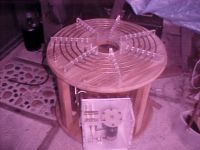
You can't see it in this photo, but this is the first coil with a hairpin tuner. The travel is only about 20", but that should be enough to give me what I need for fine tuning without the high losses of a tap and tap lead.
Re: At the assembly stage. Looking for feedback (no pun intended)
crashstudio, Sat Jun 13 2015, 04:37PM
I thought you were referring to the PFC caps in the ac conditioning circuit. The caps on the terry filter are 0.0033uF 1600V Metal Polypropylene
and here is the rest...
(2) 100 watt 1K ohm Dale resistors
(16) MOV's 1800V (Metal Oxide Varistor)
(12) 10M Ohm 1/2 Watt 5% Resistors
crashstudio, Sat Jun 13 2015, 04:37PM
Hazmatt_(The Underdog) wrote ...
The little red caps on your filter are rated for 2100V? Wow!
The little red caps on your filter are rated for 2100V? Wow!
I thought you were referring to the PFC caps in the ac conditioning circuit. The caps on the terry filter are 0.0033uF 1600V Metal Polypropylene
and here is the rest...
(2) 100 watt 1K ohm Dale resistors
(16) MOV's 1800V (Metal Oxide Varistor)
(12) 10M Ohm 1/2 Watt 5% Resistors
Print this page