another driver expieriment
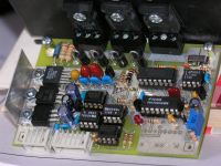
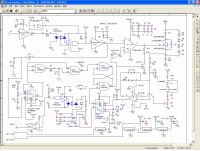
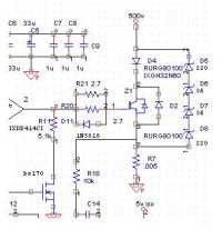
teravolt, Sun Oct 15 2006, 02:15AMI apoligize if I steped on someone elses thread but I'm excited about getting the board to work. I'm going to try to poast the scematic if any body has questions from the last thread. the only thing I don't like about this board is that I wanted the gate drive to be -5v to 20v but the IXDD414CI has a 1/3 2/3 treshold of vcc and in my last version of this pcb I could not get it go to -5 at the gate. If any body can help me I am looking for a simple scematic or IC that will take 5v logic and go to -5 and 15v and inverting and be fast. I would have used CMOS but it is to slow. thanks N.B.


Re: another driver expieriment
Marko, Sun Oct 15 2006, 11:36AM
I have little to say but O_O
Why did you use UCC's to drive just the optocouplers?
Are those boards silvered?
Marko, Sun Oct 15 2006, 11:36AM
I have little to say but O_O
Why did you use UCC's to drive just the optocouplers?
Are those boards silvered?

Re: another driver expieriment
Steve Conner, Sun Oct 15 2006, 03:24PM
Yea, it looks insanely complex! O_O What do all the extra bits do?
Steve Conner, Sun Oct 15 2006, 03:24PM
Yea, it looks insanely complex! O_O What do all the extra bits do?
Re: another driver expieriment
Marko, Sun Oct 15 2006, 04:32PM
'the extra bits' seem to be overcurrent protection, frequency divider (bistable) and a level shifter circuit made out of an UCC (?).
Entire thing is optoisolated and opto's are driven with UCC37324's again, I gueess that's for Uberspeed.
Marko, Sun Oct 15 2006, 04:32PM
'the extra bits' seem to be overcurrent protection, frequency divider (bistable) and a level shifter circuit made out of an UCC (?).
Entire thing is optoisolated and opto's are driven with UCC37324's again, I gueess that's for Uberspeed.
Re: another driver expieriment
teravolt, Sun Oct 15 2006, 06:56PM
FIRKRAGG I use the uccs to drive the optos because of there low on and off impedance. I tried using just a pull down but the off rise time was to slow. Normally these optos are inverting so the output is high when the LED is off so a standard pull down gives a great fall time and a shity rise time. Driving the LED helps speed it up. The other portion you mention is the current set point and the LT1016. The set point trimmer is just an adjustable referance for pin3. As the current through R7 goes up so does the voltage so U7 sets U1 A,B R-S FF. U1B6 does two things. it disables the IXDD414CI . Pin 2 on the driver goes to a high-Z and the BS170 turns on discharging the gate. R11 and the gate capaitance RC provides a soft shut down in a fault condition. I found this design in the IXDD414CI applications data at IXYS and moified it. it was originaly designed for bricks. The parts I added are the oneshots and optos.
U5A does two things also, 1: sets U1B, 2: sends a 1 second pulse to the LED, T-1528 F/O port, and ISO2. Fault is 1s so I can see a fault at the LED. The actual fault hapens at the falling edge about 200ns after the event. The UCC atached to the fault is used for a low impedance driver to the Zero circuitry.
U5 is used as a pulse detector and U1 C,D makes a 10ns pulse to reset U1A. Through this circuitry a pulse burst at the input will send only one 10ns reset pulse.
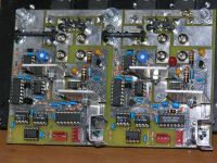
If the UCC37324 and optos are removed a F/O reciever and transmiter can be used but is more expensive. I missed a little of the scematic and added the missing gate resistors. this scematic goes from 0 to 5Mhz tested and when I get a decent scope I will have more to show. hear are some pictures of my first driver using 40n60s mini brick. this pcb works simularly and is a half bridge that has 200ns pulse widths. Hopefully I will reach the 100ns target for the 40n60s
How these circuit will behave with a tesla in a full bridge I dont know. My hope is to make a DRSSTC that is 5Mhz or regular tesla tht runs at or near CW. N.B.


Re: another driver expieriment
Marko, Fri Oct 20 2006, 08:53PM
What did you use to cover the boards? It looked like silver to me first but now it looks more like solder. Did you use some kind of flux for it?
Those boards look like factory craft...
Marko, Fri Oct 20 2006, 08:53PM
What did you use to cover the boards? It looked like silver to me first but now it looks more like solder. Did you use some kind of flux for it?
Those boards look like factory craft...
Re: another driver expieriment
teravolt, Sat Oct 21 2006, 04:21AM
I used the "expressPCB" program and in the program there is an option for ground plains. there budget 3.8*2.5" PCB has no green protective coating. I use the ground plain to reduce inductance in the circuit
teravolt, Sat Oct 21 2006, 04:21AM
I used the "expressPCB" program and in the program there is an option for ground plains. there budget 3.8*2.5" PCB has no green protective coating. I use the ground plain to reduce inductance in the circuit
Print this page