
HF gate drive experiments
Steve Conner, Thu Oct 12 2006, 12:01AMHi all
After chatting to Blackplasma, WaveRider and Firkragg about Class-E Tesla coils, I decided that I ought to try building one myself. My goal is to get as much power as possible at 27.12MHz using IRFP460s. (OK, so maybe the amount of power possible is "None", but I'll still have fun finding that out.)
Driving MOSFET gates at these frequencies is about the most difficult part, so I thought I would start with that. The gate looks like a resistance of a few ohms in series with a capacitor so big it might as well be a short-circuit.
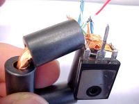
I have a HF transmitter that can put out 100W at 27.12MHz into a 50 ohm load, so my first thought was to make a step-down transformer that would transform 50 ohms to "A few" ohms. As a first attempt, I made a broadband transformer, using a ferrite core with 4 turns of coax. The core went through all 4 turns in series, and the screen was cut into 4 parts that I soldered in parallel. This gives a voltage ratio of 4:1, hence an impedance ratio of 16:1, which would transform 50 ohms to about 3 ohms. The core I used was an EMC suppressor I found in a junked printer.
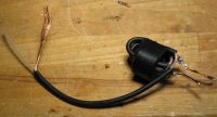
The transformer functioned as I expected up to 10MHz. I could feed it directly from my HF rig and light two 12V 20W halogen bulbs in parallel. But as I increased the frequency, the SWR began to get worse. By the time I reached 27MHz, the transmitter could barely light the bulbs before going into protection. I guessed this was due to leakage inductance, as it's not a true transmission-line transformer, even though it's made out of coax. I tried adding a variable capacitor in series with the input to resonate it, but the dip I got was very shallow, and the transmitter still wasn't happy.
So I used the antenna tuner to match it and could get both bulbs lit brightly at 27.12MHz. This worked great for about 20 seconds, then the bulbs went out as the ferrite core overheated and passed its curie point, and the coax sort of melted too...

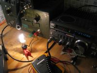
But I managed to deliver about 40W of "gate drive" into 3 ohms at 27MHz, which is a start.
Re: HF gate drive experiments
ragnar, Thu Oct 12 2006, 12:11AM
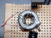
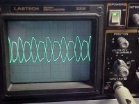
Here's the autotransformer I used to obtain synchronised inverted signals for my two-ended power gatedriver.
I regret that I'm having great difficulty matching the driver into an IRFP450 (even the transmission-line transformer seems to have too much inductance.. or something =-P)
I'll try again with a binocular core.
Below: the four-turn autotransformer is driven between turns #2 and #3. Turn #2 is grounded. Inverting and noninverting outputs can be drawn between #2 and #0, and #2 and #4 at 2x the input voltage.
Matching the outputs of the IXDD414s into an IRFP450 gate is proving difficult however -- GDT, transmission-line transformer/balun... none of it wants to work, no matter how much tweaking I can apply.
Later today I'll see if some sheer brute force can do it.


Re: HF gate drive experiments
WaveRider, Thu Oct 12 2006, 08:20AM
Steve: I've found that ferrites don't really like high-power high frequency for very long.. The powdered iron core (e.g. Amidon mix 2 or 7) toroids work better, altho leakage inductance can be higher.. (Low permeability mix). This seems to be what most hams use in their HF antenna baluns.
BP: The IXDD414 should not require matching...it already has a low impedance output.....of course, if you want resonant gate drive, that's another thing..

Re: HF gate drive experiments
ragnar, Thu Oct 12 2006, 09:11AM
Driving an IRFP450 with an IXDD414 at 10+ MHz straight of an IXDD414 isn't possible, which is why I transformer the impedance down a few times, and ensure the voltage resonates back up to a usable level.
ragnar, Thu Oct 12 2006, 09:11AM
Driving an IRFP450 with an IXDD414 at 10+ MHz straight of an IXDD414 isn't possible, which is why I transformer the impedance down a few times, and ensure the voltage resonates back up to a usable level.
Re: HF gate drive experiments
WaveRider, Thu Oct 12 2006, 09:25AM
Have you tried putting an inductor in parallel with the gate to "tune out" the gate capacitance.
The IXDD414 should then see a purely resistive load (at who knows what value...I should try a simulation with spice)
WaveRider, Thu Oct 12 2006, 09:25AM
Have you tried putting an inductor in parallel with the gate to "tune out" the gate capacitance.
from IXDD414                        To MOSFET gate
                     |  |
 --------------------|  |--------------------
                     |  |             |
                                      )
                     C                )  Inductor
                                      )  (for parallel resonance
                                      )    with gate and C)
                                      |
                                  -------
                                    ----
                                     --
The IXDD414 should then see a purely resistive load (at who knows what value...I should try a simulation with spice)
Re: HF gate drive experiments
Marko, Thu Oct 12 2006, 12:33PM
Inductor is actually rather put in series (or leakage inductance of GDT is used) so the driver doesn't 'see' anything more than his supply voltage, and resonant rise boosts gate voltage for a Q factor.
For this reason it's generally better to use a GDT, make driver run at relatively high voltage wich is stepped down with GDT, to just few volts. Resonant rise with gate capacitance lifts it to reasonable level, while reducing lload on the chip (since most of power is resonantly conserved with each cycle instead being shorted to ground).
It is completely normal for a common EMI ferrite core to blow up at 27Mhz 100W.
At that power level I knew to heat up those cores at 100kHz O_O
Re: HF gate drive experiments
ragnar, Thu Oct 12 2006, 01:14PM
I've only ever tried putting a parallel in series with the gate. I guess my flagrant ignorance is showing through, here
ragnar, Thu Oct 12 2006, 01:14PM
wrote ...
Have you tried putting an inductor in parallel with the gate to "tune out" the gate capacitance.
Have you tried putting an inductor in parallel with the gate to "tune out" the gate capacitance.
I've only ever tried putting a parallel in series with the gate. I guess my flagrant ignorance is showing through, here

Re: HF gate drive experiments
WaveRider, Thu Oct 12 2006, 01:50PM
By paralleling the inductor ant the gate, it should transform the gate resistance to a higher value.. parallel resonance should give an impedance proportional to 1/Rgate... in fact, it should be around
Rin_parallel approx L / (C * Rgate)
there will be a reactive (usually capacitive) component, but by judicious choice of L, you can make it small compared to Rin.
The main problem is the inductor will have a fairly small value... A couple of small turns of fat wire (50-60nH) should do the trick...
This may pose practical problems with tune-up, tho'...
Re: HF gate drive experiments
ragnar, Thu Oct 12 2006, 02:15PM
Since I managed to rip a 12MHz crystal off a dead CRT monitor board, I have a 12MHz fixed SSTC... not 13.56.
Edit: I canned the idea of any inductors after them not doing much... but now I have a nice 0V - 12V sinewave drive on the gate of my IRFP450... at 12MHz I'll attach pics soon.
My gatedriver assembly is drawing 1.4A at 12... 16W.. probably at least 10-12W being dissipated in the gate, I'd guess?
Re: HF gate drive experiments
ragnar, Fri Oct 13 2006, 05:14AM
OK, working a little more reliably now, limited only by the fact I haven't heatsinked the IRFP450.
It probably would have been better value for my time to try and find someone who would sell me a DEIC420, but even then I couldn't afford it if I wanted to.
Here's the proof:
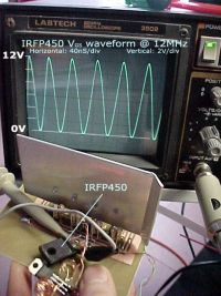
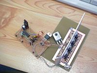
Ham radio not included. Or required
ragnar, Fri Oct 13 2006, 05:14AM
OK, working a little more reliably now, limited only by the fact I haven't heatsinked the IRFP450.
It probably would have been better value for my time to try and find someone who would sell me a DEIC420, but even then I couldn't afford it if I wanted to.

Here's the proof:


Ham radio not included. Or required

Re: HF gate drive experiments
..., Fri Oct 13 2006, 05:55AM
GO PB
You never cease to amaze me... I couldn't even get decent gate drive at 700khz, you have perfect drive at 12mhz!
And my old standby, I want plasma!
..., Fri Oct 13 2006, 05:55AM
GO PB

You never cease to amaze me... I couldn't even get decent gate drive at 700khz, you have perfect drive at 12mhz!
And my old standby, I want plasma!
Re: HF gate drive experiments
Avalanche, Fri Oct 13 2006, 07:57AM
Nice one, looks like you're getting that gate drive perfected! What are the heatsinked devices on the pcb, are they normal transistors or mosfets? Just trying to figure out what you're using now schematic wise
I'm off to Maplin in a few minutes when the traffic has died down, couldn't sleep properly thinking about class-e

Re: HF gate drive experiments
Steve Conner, Fri Oct 13 2006, 10:30AM
Wow, neat! Are you using any sort of matching network between the gate driver chips and the MOSFET gate, or just hard driving it? Also, is that an IRFP450LC or just a plain IRFP450?
Steve Conner, Fri Oct 13 2006, 10:30AM
Wow, neat! Are you using any sort of matching network between the gate driver chips and the MOSFET gate, or just hard driving it? Also, is that an IRFP450LC or just a plain IRFP450?
Re: HF gate drive experiments
ragnar, Fri Oct 13 2006, 11:10AM
Hi Steve, Avalanche,
The heatsinked IXDD414s on the PCB are top secret, and I can't tell you what they are. =-P
Ah, does a resistor count as a matching network? I'd also like to proudly note this is a plain boring cheap IRFP450, as opposed to the LC version which costs 5x as much. ^^
No series L or series C, I'm just 'hard driving',yes (although not hard enough...).
Re: HF gate drive experiments
WaveRider, Fri Oct 13 2006, 01:07PM
Goodo BP! It's always best to go for brute force first.. Make it look pretty later..........
WaveRider, Fri Oct 13 2006, 01:07PM
Goodo BP! It's always best to go for brute force first..
 Make it look pretty later..........
Re: HF gate drive experiments
teravolt, Sat Oct 14 2006, 05:08AM
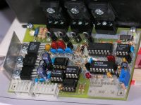
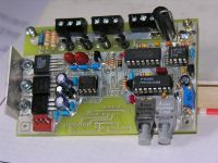
Hello all, I have also made a version of driver that uses the IXDD414CI. This is my second version of this circuit and I have been able to get 0 to 5Mhz out of it. The smallest pulse width is about 80ns. It has on board current protection and sends out a fault pulse. this driver is isolated to about 1200v by opto's and uses a raw dc foating supply to power the high side. I'm not able to give formal shematic or o-scope print at this time but will in a thread later. Thease drivers are pritty robust and I have goten them down to 20ns on a proto board. Presantly I am driving a standard igbt IXGH32N60C with about 1.3 ohms for a time of 100ns with about 16ns rise and fall times. This pcb will accomidate a F/O link or directly with optos.

Re: HF gate drive experiments
Marko, Sat Oct 14 2006, 12:48PM
These boards look absolutely awesome teravolt.
Have any higher resolution pics or schematics?
(I'm wondering what all those IC's and strange looking components are for )
)
Marko, Sat Oct 14 2006, 12:48PM
These boards look absolutely awesome teravolt.
Have any higher resolution pics or schematics?
(I'm wondering what all those IC's and strange looking components are for
 )
)Re: HF gate drive experiments
Avalanche, Sat Oct 14 2006, 02:40PM
Nice boards there!
Anyway along the same lines as BP's gate driver torture, I tried the MC34151P driver at 12Mhz yesterday. It claims to be a high-speed driver, and it has a schmitt triggered input. Just not high enough though With 12Mhz matched into its input, initial power-on looked promising with a fairly good sine-looking output, which didn't last long before it died away to nothing
  This was with no load. The chip didn't even get hot though, it just seems to shut down! Switching off for a few seconds and back on does the same, and I just cannot kill the chip.
So anyway I now have a nice 0.3 watt 4-24Mhz transmitter using various crystals and harmonics of, lets see if I can do anything constructive
Avalanche, Sat Oct 14 2006, 02:40PM
Nice boards there!
Anyway along the same lines as BP's gate driver torture, I tried the MC34151P driver at 12Mhz yesterday. It claims to be a high-speed driver, and it has a schmitt triggered input. Just not high enough though
 With 12Mhz matched into its input, initial power-on looked promising with a fairly good sine-looking output, which didn't last long before it died away to nothing
  This was with no load. The chip didn't even get hot though, it just seems to shut down! Switching off for a few seconds and back on does the same, and I just cannot kill the chip.
So anyway I now have a nice 0.3 watt 4-24Mhz transmitter using various crystals and harmonics of, lets see if I can do anything constructive

Re: HF gate drive experiments
teravolt, Sat Oct 14 2006, 06:45PM
hears a larger picture, my next version of this will use 2 IXDD414CI in parallel for driving brick gates at 30A peak. it will have no current feadback and be just a raw driver but will be fully isolated. I am hoping to get 100ns rise and fall times for large bricks but I don't know if is pausible. The trick is to reduce resistance and inductance as much as pausible between the driver and gate. The only problem with thease drivers is that they need a seperate power supply or DC to DC converter if you want to float them wich leeds to complexity of the bridge. N.B.


Re: HF gate drive experiments
Avalanche, Tue Oct 31 2006, 06:19PM
Anyone had any further luck with gate torture?
After quietly building several prototypes and blowing them up over the last few days, I've managed to get a fairly nice gate drive into an IRFP460 at 12Mhz, using a crystal oscillator and a class A-B RF amplifier matched into the gate. The A-B output stage is driven by the 74HCT logic chip, via a mini impedence matching transformer into the bases.
I am now absolutely gutted though, because 5 minutes ago I was running the thing without any heatsinks on my transistors (couldn't wait to check it out ) Nice 12Mhz across the gate went down to nothing as I turned up the bias too much, and the board hissed at me
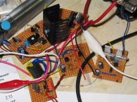
As soon as I manage to find some replacement transistors (I think I have some lying around) I'll replace them, fit a heatsink, and post some scope shots, but for now you'll have to imagine the scope shots and just make do with a picture of my HF driver board
(I think I need to cut down on capacitors next time )
)
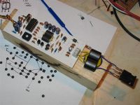
Failed prototypes:
Avalanche, Tue Oct 31 2006, 06:19PM
Anyone had any further luck with gate torture?
After quietly building several prototypes and blowing them up over the last few days, I've managed to get a fairly nice gate drive into an IRFP460 at 12Mhz, using a crystal oscillator and a class A-B RF amplifier matched into the gate. The A-B output stage is driven by the 74HCT logic chip, via a mini impedence matching transformer into the bases.
I am now absolutely gutted though, because 5 minutes ago I was running the thing without any heatsinks on my transistors (couldn't wait to check it out
 ) Nice 12Mhz across the gate went down to nothing as I turned up the bias too much, and the board hissed at me
As soon as I manage to find some replacement transistors (I think I have some lying around) I'll replace them, fit a heatsink, and post some scope shots, but for now you'll have to imagine the scope shots and just make do with a picture of my HF driver board

(I think I need to cut down on capacitors next time
 )
)
Failed prototypes:

Re: HF gate drive experiments
ragnar, Tue Oct 31 2006, 08:02PM
Fantastic!
I'm impressed that you can get away with the ferrites -- I found that a single turn around anything exceeded the 53nH permissible for resonance at 12MHz with the IRFP450... but you've got two turns =P
What's the secret? ^^
ragnar, Tue Oct 31 2006, 08:02PM
Fantastic!
I'm impressed that you can get away with the ferrites -- I found that a single turn around anything exceeded the 53nH permissible for resonance at 12MHz with the IRFP450... but you've got two turns =P
What's the secret? ^^
Re: HF gate drive experiments
Avalanche, Wed Nov 01 2006, 01:03PM
Probably the double 'binocular' core if anything... I found using a single ferrite ring I could barely get any decent coupling. Using the double I get a lot less leakage inductance (and it's easier to wind). I've calculated that I need .059uH for resonance, which is tiny! I'm not sure what grade the ferrite is, but they are the 'suppress noise on wires' type. I haven't actually tuned the gate drive for resonance yet, I just fired it up and it looked alright I'm going to have a go at fixing it back up now.
I can increase the voltage on the final output stage up to about 28 volts safely, and wind the transformer to suit, to get crazily low output impedences. The only problem is that the current draw on the primary then increases beyond what the transistors can handle, so they fizz out.
Have you measured the gate capacitance on a MOSFET, as they vary wildly especially between different brands.
Avalanche, Wed Nov 01 2006, 01:03PM
Probably the double 'binocular' core if anything... I found using a single ferrite ring I could barely get any decent coupling. Using the double I get a lot less leakage inductance (and it's easier to wind). I've calculated that I need .059uH for resonance, which is tiny! I'm not sure what grade the ferrite is, but they are the 'suppress noise on wires' type. I haven't actually tuned the gate drive for resonance yet, I just fired it up and it looked alright
 I'm going to have a go at fixing it back up now.
I can increase the voltage on the final output stage up to about 28 volts safely, and wind the transformer to suit, to get crazily low output impedences. The only problem is that the current draw on the primary then increases beyond what the transistors can handle, so they fizz out.
Have you measured the gate capacitance on a MOSFET, as they vary wildly especially between different brands.
Re: HF gate drive experiments
Marko, Wed Nov 01 2006, 01:22PM
Gate capacitances are exactly defined in mosfet's datasheet.
IRFP450 from fairchild has about 2nF, IRF's has 2,6 and etc. (it seems to vary somewhat).
You can try using thin strip instead of wire soldered as close as possible to mosfet, use highest coupling possible, or try some of those low-permeability HF powder cores and see if they are a good trade for inductance/coupling.
I admit I got bored of high frequency hunt since it's hard to get big sparks at >10Mhz. Efficiency drops quite fast over there due to mosfet's delays!
Re: HF gate drive experiments
Avalanche, Wed Nov 01 2006, 02:25PM
Yeah it looks like there is still way too much leakage afterall, even on that transformer.
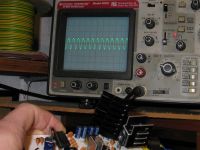
Here's some waveforms anyway, at 12Mhz into the gate of one IRFP460. The overall voltage is only about 2v peak to peak, so it isn't ideal. I was hoping to get at least 4v. However, the MOSFET itself is getting warm - about as warm as the heatsinks on the amplifier, so at least some power is going to the right place I don't think I am driving the final power output transistors hard enough just from the TTL, i'm going to try and push them a bit more. I will probably also need to add a DC bias to the gate of the MOSFET.
Gate waveform at 12Mhz
perfect layout and component choice, ready for mass production
Avalanche, Wed Nov 01 2006, 02:25PM
Yeah it looks like there is still way too much leakage afterall, even on that transformer.
Here's some waveforms anyway, at 12Mhz into the gate of one IRFP460. The overall voltage is only about 2v peak to peak, so it isn't ideal. I was hoping to get at least 4v. However, the MOSFET itself is getting warm - about as warm as the heatsinks on the amplifier, so at least some power is going to the right place
 I don't think I am driving the final power output transistors hard enough just from the TTL, i'm going to try and push them a bit more. I will probably also need to add a DC bias to the gate of the MOSFET.
Gate waveform at 12Mhz

perfect layout and component choice, ready for mass production


Re: HF gate drive experiments
ragnar, Sat Nov 04 2006, 12:26PM
Using my freshly acquired cheap thrills signal generator I had a little play around with some ferrite combinations.
At the (careful) expense of a short length of quality coax, I had a length of crosswoven braiding, and a hollow tube of thick, fingercutting copper foil.
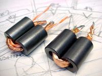
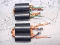
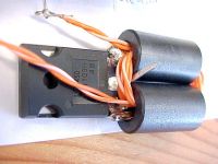
If you look at the FIRST picture, the LEFT transformer is formed with two small chokes. The primary is three turns of twisted-pair (wires in parallel). The secondary is a single turn of thick copper braiding (folded double to make it 2x as thick). After connecting an IRFP450 across (comparable input capacitance I measured for this particular FET is 2.67nF) to the secondary, and sweeping the primary with newfangled signalgen, it resonated at 14.35MHz, (implying ~46nH in a perfect world.)
If you look at the FIRST picture, the RIGHT transformer is wound with two turns of green twisted-pair (wires in parallel). The secondary is a single turn of hollow copper foil which *perfectly conforms (sizewize) to the inside wall of the ferrite. If you look carefully, you can see that the two-turn primary actually runs INSIDE the foil, and I've spliced it out of the foil at the ends, and to tighten the second turn. After connecting the same IRFP450 on the secondary, it was revealed to resonate at 13.6MHz, (implying ~51nH in a perfect world.)
Tomorrow I'll try combining all four ferrites into a circlar loop (though this may be heading the wrong way). Failing that... parallel secondaries, drive the primaries in series. =)


Re: HF gate drive experiments
Avalanche, Sat Nov 04 2006, 01:10PM
woh, getting closer now! I put a single turn copper wire secondary on my transformer above, it improved things slightly but still nowhere near good enough. Going by your results, it must have been fairly close afterall, as it's a very similar transformer. Maybe I just need to stand well back and push more power into the primary

Re: HF gate drive experiments
Marko, Sat Nov 04 2006, 01:22PM
If you have enough copper foil you can try putting a ferrite toroid on a double-sided PCB; drilling hole in the middle and then envelopint entire toroid with foil for lowest possible inductance (wider, flatter winding = less inductance) and then simply wind primary winding on it.
I hope you got what i'm trying to say ^^
Re: HF gate drive experiments
Avalanche, Sat Nov 04 2006, 05:06PM
Just gave litz wire a whirl, and it seems to perform nicely. Probably no real advantage except it's easier to push onto the core When I get around to it I'll work out the inductance properly like BP did, into a known capacitance value.
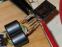
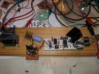
Something which has surprised me is how much difference the straight wire inductance makes going to the MOSFET G-S, it's easy to overlook it when probing. Even though there are huge thick solder joints you still have to be careful where the probes go. It probably isn't helped by the fact I am using a tacky 1:1 probe also...
In the pics nothing has changed except the point of probage... I'll soon be drilling holes in the FET to try and hook up to the die


slight progress update...
I think it's resonant now, all I've done is extend the length of the gate slightly and that seems to add enough
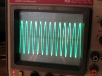
However, all I can get is around 1.5x the voltage I would get from the turns ratio, by resonant action. I think the q-factor is so bad it makes it pretty much impossible to achieve any decent amount of rise, but I could be wrong. I've also changed a few component values in my rf driver which has helped a lot! Scope shot is 100nS, 1v/div. I'm wondering if (when I add gate bias) this is 'enough'?
Avalanche, Sat Nov 04 2006, 05:06PM
Just gave litz wire a whirl, and it seems to perform nicely. Probably no real advantage except it's easier to push onto the core
 When I get around to it I'll work out the inductance properly like BP did, into a known capacitance value.
 Something which has surprised me is how much difference the straight wire inductance makes going to the MOSFET G-S, it's easy to overlook it when probing. Even though there are huge thick solder joints you still have to be careful where the probes go. It probably isn't helped by the fact I am using a tacky 1:1 probe also...
In the pics nothing has changed except the point of probage... I'll soon be drilling holes in the FET to try and hook up to the die


slight progress update...
I think it's resonant now, all I've done is extend the length of the gate slightly and that seems to add enough

However, all I can get is around 1.5x the voltage I would get from the turns ratio, by resonant action. I think the q-factor is so bad it makes it pretty much impossible to achieve any decent amount of rise, but I could be wrong. I've also changed a few component values in my rf driver which has helped a lot! Scope shot is 100nS, 1v/div. I'm wondering if (when I add gate bias) this is 'enough'?


Re: HF gate drive experiments
ragnar, Sun Nov 05 2006, 12:03AM
Of course, what you see on the scope isn't what's actually on the gate, but should be near enough... if the gate is actually swinging 5.5Vp/p, it might be worth trying class-E (the swing of voltage/current helps the gate to turn on/off at the right times...?) you'd notice that the gate impedance will change (wildly throughout the cycle) as you start to switch actual volts. ^^
Assuming this isn't your last FET, by all means hook it up to some power!
After some more twiddling, I'm going to recreate my two-IXDD414 driver (remember the one with the nasty inverted waveforms) in the hope of now driving my little mess of transformers. In fact, scrap the inverted signals, I'll put two in parallel instead.
edit:
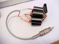
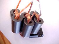
I made three identical copies of the orange-twisted-pair-and-braid ferrite pair... with the exception that the secondary now exits out the opposite side to the primary.
One by itself: Resonates at 12.2MHz, implying ~63nH
Two in parallel: Resonates at 14.1MHz, implying ~47nH
Three in parallel: Resonates at 15.2MHz, implying ~41nH
The Q is sufficiently low that the acceptable 'peak' ranges ~0.5MHz
Ack.
edit2:
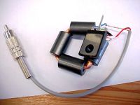
For the sake of it I tried the four-ferrite combo: Three primary turns, each made from a parallel twisted pair. The secondary is a close-fitting copper foil. It's crap -- resonates at 11.8MHz, implying 68nH.
Splat.
---
Firkragg, I know what you mean -- but instead of copper foil (which gets messy), I meant to try it with pipe through the middle and half-torus shaped washers. Even after trying copper foil, it all seemed to be in vain.
ragnar, Sun Nov 05 2006, 12:03AM
Of course, what you see on the scope isn't what's actually on the gate, but should be near enough... if the gate is actually swinging 5.5Vp/p, it might be worth trying class-E (the swing of voltage/current helps the gate to turn on/off at the right times...?) you'd notice that the gate impedance will change (wildly throughout the cycle) as you start to switch actual volts. ^^
Assuming this isn't your last FET, by all means hook it up to some power!
After some more twiddling, I'm going to recreate my two-IXDD414 driver (remember the one with the nasty inverted waveforms) in the hope of now driving my little mess of transformers. In fact, scrap the inverted signals, I'll put two in parallel instead.
edit:
I made three identical copies of the orange-twisted-pair-and-braid ferrite pair... with the exception that the secondary now exits out the opposite side to the primary.
One by itself: Resonates at 12.2MHz, implying ~63nH
Two in parallel: Resonates at 14.1MHz, implying ~47nH
Three in parallel: Resonates at 15.2MHz, implying ~41nH
The Q is sufficiently low that the acceptable 'peak' ranges ~0.5MHz
Ack.


edit2:
For the sake of it I tried the four-ferrite combo: Three primary turns, each made from a parallel twisted pair. The secondary is a close-fitting copper foil. It's crap -- resonates at 11.8MHz, implying 68nH.
Splat.


---
Firkragg, I know what you mean -- but instead of copper foil (which gets messy), I meant to try it with pipe through the middle and half-torus shaped washers. Even after trying copper foil, it all seemed to be in vain.
Re: HF gate drive experiments
Avalanche, Sun Nov 05 2006, 12:28PM
Excellent stuff! So with the improved setup you should be able to add some real inductance and get some resonant rise in the gate!
I found a 10Mhz crystal in an old cable modem yesterday... so I think I will probably 'cheat' and use that with my current setup edit: scrap that idea, I ruined it trying to remove it. Back to 12Mhz
Avalanche, Sun Nov 05 2006, 12:28PM
Excellent stuff! So with the improved setup you should be able to add some real inductance and get some resonant rise in the gate!
I found a 10Mhz crystal in an old cable modem yesterday... so I think I will probably 'cheat' and use that with my current setup
 edit: scrap that idea, I ruined it trying to remove it. Back to 12Mhz
Re: HF gate drive experiments
ragnar, Mon Nov 06 2006, 01:54AM
I've found my "signal generator" (ha) really handy for sweeping each new setup... as soon as I put any kind of power into the FET, the Fres drops as does the Q, but I'm still above the 10MHz mark... I'd really like to be at the 13.56MHz mark, however, but it's still really nice to have a ballpark estimate of the Fres/inductance before I start each time ^^
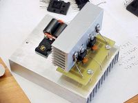
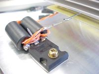
When I'd finished work yesterday afternoon, I milled a small board to accommodate two IXDD414s in parallel, a divider to float the input voltage at Vcc/2 (so that my signal generator could swing it), tantalum+ceramic power bypass caps (soldered directly to legs) and two capacitors for the fixed end of the halfbridge.
With 12V, 0.535A in, I'm swinging an IRFP450 at 11MHz at > 8Vp/p through a 4:1 transformer. (Q~2.67, pah)... the usable frequency range is pretty wide, and I can get 8V or more on the FET between ~10MHz and 11.5MHz.
I'm very happy with the efficiency, considering it took me IIRC ~1.6A at 12V to hard-drive 12Vp/p on the same FET at 12MHz.
And now, if I want more volts, it's easier to increase the supply voltage than to try and make a fullbridge from more IXDDs. I'll be a happy chap if I can get 12Vp/p, 11MHz on an IRFP450 with only two chips =D
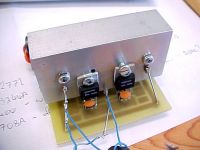
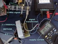
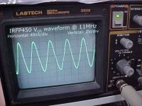
edit: update -- increasing the supply voltage to 18V caused a current draw of 1.06A and the waveform across the MOSFET is now 12Vp/p and I twiddled the freq to 11.5MHz.
The IXDDs do get warm though ^^
Now, time to build a boring variable-voltage power supply for more twiddling.
edit: update2 -- scrap the power supply, I wanna see some sparks (and hopefully not from the FET), which means winding a resonator of some description and making this mess rigid with a heatsink etc. =D
And my cheap thrills signal generator will prove mighty handy for sweeping the resonator Fres, too. Why didn't I build this years ago? ^^
Achoo.
ragnar, Mon Nov 06 2006, 01:54AM
I've found my "signal generator" (ha) really handy for sweeping each new setup... as soon as I put any kind of power into the FET, the Fres drops as does the Q, but I'm still above the 10MHz mark... I'd really like to be at the 13.56MHz mark, however, but it's still really nice to have a ballpark estimate of the Fres/inductance before I start each time ^^
When I'd finished work yesterday afternoon, I milled a small board to accommodate two IXDD414s in parallel, a divider to float the input voltage at Vcc/2 (so that my signal generator could swing it), tantalum+ceramic power bypass caps (soldered directly to legs) and two capacitors for the fixed end of the halfbridge.
With 12V, 0.535A in, I'm swinging an IRFP450 at 11MHz at > 8Vp/p through a 4:1 transformer. (Q~2.67, pah)... the usable frequency range is pretty wide, and I can get 8V or more on the FET between ~10MHz and 11.5MHz.
I'm very happy with the efficiency, considering it took me IIRC ~1.6A at 12V to hard-drive 12Vp/p on the same FET at 12MHz.
And now, if I want more volts, it's easier to increase the supply voltage than to try and make a fullbridge from more IXDDs. I'll be a happy chap if I can get 12Vp/p, 11MHz on an IRFP450 with only two chips =D


edit: update -- increasing the supply voltage to 18V caused a current draw of 1.06A and the waveform across the MOSFET is now 12Vp/p and I twiddled the freq to 11.5MHz.
The IXDDs do get warm though ^^
Now, time to build a boring variable-voltage power supply for more twiddling.

edit: update2 -- scrap the power supply, I wanna see some sparks (and hopefully not from the FET), which means winding a resonator of some description and making this mess rigid with a heatsink etc. =D
And my cheap thrills signal generator will prove mighty handy for sweeping the resonator Fres, too. Why didn't I build this years ago? ^^
Achoo.


Re: HF gate drive experiments
Steve Conner, Mon Nov 06 2006, 10:08AM
I guess you can't get stray inductance any lower than that! Richie explained to me that you can get the frequency to go higher than the self-resonant frequency by connecting a capacitor in series with the primary, so that could be the next thing to try. It's pretty impressive as is though!
Steve Conner, Mon Nov 06 2006, 10:08AM
I guess you can't get stray inductance any lower than that!
 Richie explained to me that you can get the frequency to go higher than the self-resonant frequency by connecting a capacitor in series with the primary, so that could be the next thing to try. It's pretty impressive as is though!
Re: HF gate drive experiments
ragnar, Mon Nov 06 2006, 10:10AM
I was about to mention that putting a capacitor in series with the gate would lower the overall capacitance, albeit increasing the voltage you need to drive it to, right?
ragnar, Mon Nov 06 2006, 10:10AM
I was about to mention that putting a capacitor in series with the gate would lower the overall capacitance, albeit increasing the voltage you need to drive it to, right?
Re: HF gate drive experiments
Steve Conner, Mon Nov 06 2006, 10:12AM
Yes, that's pretty much the idea. Capacitors in series have a lower capacitance, so the resonant frequency is pushed up. The capacitor goes in series with the primary though, ie the driver side not the gate side. It has the same effect electrically, but you don't have to worry so much about the physical size of it increasing stray inductance.
Re: HF gate drive experiments
Avalanche, Mon Nov 06 2006, 11:15AM
Awesome, I thought about putting a capacitor directly in series with the gate, but thought I must be missing something and it couldn't be that easy to reduce the gate capacitance
Only problem is it will form a potential divider, so the voltage will need a good boost. Won't the extra cap need to be a bit larger than the gate capacitance too?
Avalanche, Mon Nov 06 2006, 11:15AM
Awesome, I thought about putting a capacitor directly in series with the gate, but thought I must be missing something and it couldn't be that easy to reduce the gate capacitance

Only problem is it will form a potential divider, so the voltage will need a good boost. Won't the extra cap need to be a bit larger than the gate capacitance too?
Re: HF gate drive experiments
Steve Conner, Mon Nov 06 2006, 11:43AM
It's only really worthwhile if it's done as part of tuning the gate drive circuit to resonance. The circuit will have a natural frequency that it resonates at, set by the gate capacitance and the transformer and wiring leakage inductance.
If you want to operate below this frequency, then you need to add a series inductor to move the resonant frequency down. If you want to operate above it, you need a series capacitor to move the resonant frequency up.
Re: HF gate drive experiments
Avalanche, Mon Nov 06 2006, 12:23PM
Yeah I get that bit how you can shift the resonant frequency up by adding series capacitance to the LC, but won't the overall charge accumulated in the mosfet gate be halved? I was under the impression that the mosfet gate had to be fully charged before the thing could conduct properly I'm just going by what would happen if it weren't a resonant circuit, I'm probably totally wrong again anyway
Avalanche, Mon Nov 06 2006, 12:23PM
Yeah I get that bit how you can shift the resonant frequency up by adding series capacitance to the LC, but won't the overall charge accumulated in the mosfet gate be halved? I was under the impression that the mosfet gate had to be fully charged before the thing could conduct properly
 I'm just going by what would happen if it weren't a resonant circuit, I'm probably totally wrong again anyway
Re: HF gate drive experiments
Marko, Mon Nov 06 2006, 12:51PM
Gate charge is same, except series cap makes a voltage divider vith mosfet's capacitance.
But, you also get some Q-factor increase so you may need just to adjust input power a bit.
With stronger drivers it shouldn't be a problem though.
Making a good matching transformer with low ohmic resistance may also help a lot to increase Q if we need that.
Re: HF gate drive experiments
Avalanche, Mon Nov 06 2006, 02:46PM
Aha, I think I see where this is going, hopefully with enough Q the voltage can resonate back up hopefully without having to change anything
So if I add roughly 4nF of caps to the primary, my total will be near the 1.76nF required to resonate with .1uH. My plan is to add a small variable inductor in series with the gate, so I can adjust it until it hits resonance.
The only problem is that I cannot add a capacitor on the primary, because I'm using a center tapped primary
But if it's the way forward I'll have to do some serious rethinking. Would there be any reason why I cannot put say a 1nF cap in series with the primary, and add a larger inductor to the gate? (apart from the fact that the voltage would be tiny, so I'd have to increase the input) I just want to know if i'm missing anything before I go and make a new high voltage driver that doesn't need a center tapped primary...
update! It does resonant back up enough!
I cobbled together a small board to hold an IRFP460, some series caps and an inductor. Because of my driver design I decided to put the caps directly in series with the gate, on the secondary side, and it works pretty well. I've used 4x1nF caps (rated at 400v each, I guess they're poly caps) and a small series inductor below that to bring the total inductance in the secondary side to .1uH, with as little of that as possible on the source side of the fet.
Without changing anything on my driver since the last photo, the voltage resonates back to to 7v p-p across g-s, which can't be that bad considering the 4:1 turns ratio on the transformer, and the capacitive divider formsed by the gate and the 'gate mmc' This is with 15volts into my driver board.
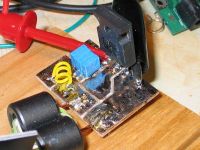
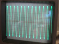
(1v, .1uS/div)
Avalanche, Mon Nov 06 2006, 02:46PM
Aha, I think I see where this is going, hopefully with enough Q the voltage can resonate back up hopefully without having to change anything

So if I add roughly 4nF of caps to the primary, my total will be near the 1.76nF required to resonate with .1uH. My plan is to add a small variable inductor in series with the gate, so I can adjust it until it hits resonance.
The only problem is that I cannot add a capacitor on the primary, because I'm using a center tapped primary

But if it's the way forward I'll have to do some serious rethinking. Would there be any reason why I cannot put say a 1nF cap in series with the primary, and add a larger inductor to the gate? (apart from the fact that the voltage would be tiny, so I'd have to increase the input) I just want to know if i'm missing anything before I go and make a new high voltage driver that doesn't need a center tapped primary...
update! It does resonant back up enough!
I cobbled together a small board to hold an IRFP460, some series caps and an inductor. Because of my driver design I decided to put the caps directly in series with the gate, on the secondary side, and it works pretty well. I've used 4x1nF caps (rated at 400v each, I guess they're poly caps) and a small series inductor below that to bring the total inductance in the secondary side to .1uH, with as little of that as possible on the source side of the fet.
Without changing anything on my driver since the last photo, the voltage resonates back to to 7v p-p across g-s, which can't be that bad considering the 4:1 turns ratio on the transformer, and the capacitive divider formsed by the gate and the 'gate mmc'
 This is with 15volts into my driver board.

(1v, .1uS/div)
Re: HF gate drive experiments
ragnar, Tue Nov 07 2006, 12:36PM
Very nice, Avalanche! Though I'm not sure if it'd have been more straightforward to add the C to the primary ^^ (well, that's a given in my case ) I'll have to outpwn your IRFP460 with 12Vp/p, 11.5MHz for IRFP450 19.08W input.
I found my last LM317 today, too, and with some big heatsinks I can now make a variable power supply for safer tweaking. =D
Next target, 13.56MHz, and sparks, of course. ^^
ragnar, Tue Nov 07 2006, 12:36PM
Very nice, Avalanche! Though I'm not sure if it'd have been more straightforward to add the C to the primary ^^ (well, that's a given in my case
 ) I'll have to outpwn your IRFP460 with 12Vp/p, 11.5MHz for IRFP450 19.08W input.
I found my last LM317 today, too, and with some big heatsinks I can now make a variable power supply for safer tweaking. =D
Next target, 13.56MHz, and sparks, of course. ^^
Re: HF gate drive experiments
Avalanche, Tue Nov 07 2006, 03:10PM
I'm starting to consider winding a resonator too and making some sparks, I almost forgot about that part
outpwnage, doh! I think I can boost the p-p value on my gate a bit more, just by turning up the input, but i'm max'd out at 15v in at the moment. I'll just have to find a bigger transformer to run the driver, then see (or smell) what happens...
I'm quite happy with the performance of the capacitance on the secondary side, so will probably stick with it and my current driver setup. Lots of small caps in parallel seem to perform better than just one large cap at HF, and I have hundreds of these 1nf's anyway. Just need to get on with the class-e part now!
So far this has kept me entertained a lot longer than my medium frequency sstcs. I was looking at HV mosfets the other day, and various techniques to run the things in parallel. Still haven't dropped the idea of base feeding...
Avalanche, Tue Nov 07 2006, 03:10PM
I'm starting to consider winding a resonator too and making some sparks, I almost forgot about that part

outpwnage, doh!
 I think I can boost the p-p value on my gate a bit more, just by turning up the input, but i'm max'd out at 15v in at the moment. I'll just have to find a bigger transformer to run the driver, then see (or smell) what happens...
I'm quite happy with the performance of the capacitance on the secondary side, so will probably stick with it and my current driver setup. Lots of small caps in parallel seem to perform better than just one large cap at HF, and I have hundreds of these 1nf's anyway. Just need to get on with the class-e part now!
So far this has kept me entertained a lot longer than my medium frequency sstcs. I was looking at HV mosfets the other day, and various techniques to run the things in parallel. Still haven't dropped the idea of base feeding...

Re: HF gate drive experiments
Sulaiman, Tue Nov 07 2006, 04:19PM
Have you tested the gate drive with a load/power on the drain yet?
The miller (feedback) capacitance will change the load quite a bit I think.
At such high frequency you may need to consider 'cascode' operation
Sulaiman, Tue Nov 07 2006, 04:19PM
Have you tested the gate drive with a load/power on the drain yet?
The miller (feedback) capacitance will change the load quite a bit I think.
At such high frequency you may need to consider 'cascode' operation
Re: HF gate drive experiments
Avalanche, Tue Nov 07 2006, 05:13PM
I haven't tried that yet, but i'm about to... I'm guessing I will probably have to spend a while getting the nice gate drive back again
I briefly ran across the 'cascode' thing when I was looking into running mosfets in series for higher voltage, I never thought of the advantage of dividing the mosfet capacitance as well by doing that so I suppose that's good news.
-Update- 10v p-p, 12Mhz
Avalanche, Tue Nov 07 2006, 05:13PM
I haven't tried that yet, but i'm about to... I'm guessing I will probably have to spend a while getting the nice gate drive back again

I briefly ran across the 'cascode' thing when I was looking into running mosfets in series for higher voltage, I never thought of the advantage of dividing the mosfet capacitance as well by doing that so I suppose that's good news.
-Update- 10v p-p, 12Mhz

Re: HF gate drive experiments
ragnar, Thu Nov 09 2006, 12:10AM
For a better impedance ratio, I've decided to go back to four IXDDs, two in parallel for each leg of a fullbridge (24V/turn, anyone? =P)
And so I can outpwn j00 all, my target remains at 13.56MHz (ISM band). ^^
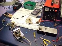
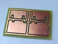
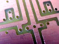
ragnar, Thu Nov 09 2006, 12:10AM
For a better impedance ratio, I've decided to go back to four IXDDs, two in parallel for each leg of a fullbridge (24V/turn, anyone? =P)
And so I can outpwn j00 all, my target remains at 13.56MHz (ISM band). ^^


Re: HF gate drive experiments
Avalanche, Thu Nov 09 2006, 12:19PM
pwned
I'm having some minor problems with my driver now, after increasing the input voltage. As it heats up, the drive waveform slowly deteriorates, so I have to re-adjust the bias to get it back. I've made some huge heatsinks to combat it though.
One thing I did find when switching an actual load with the mosfet was that my gate waveforms actually seemed to improve - which was a nice surprise.
bp, you have the same calculator as me
Avalanche, Thu Nov 09 2006, 12:19PM
pwned

I'm having some minor problems with my driver now, after increasing the input voltage. As it heats up, the drive waveform slowly deteriorates, so I have to re-adjust the bias to get it back. I've made some huge heatsinks to combat it though.
One thing I did find when switching an actual load with the mosfet was that my gate waveforms actually seemed to improve - which was a nice surprise.
bp, you have the same calculator as me

Re: HF gate drive experiments
Marko, Thu Nov 09 2006, 12:56PM
You definitely have bad caps somewhere in the circuit.
I had some of those little blue ones and after I used them as shunt cap they melted, spilled their guts and embedded into surrounding plastic objects and themselves mutually (philadephia experiment?)
You have plenty about that in my and bp's old threads.
All caps must be polypropylene, same for gate drive, almost anything else will heat up dramatically and change capacitance with that.
Also try to move them away from mosfet and heatsink physically (little inductance won't bother you since you aare already tuning the circuit).
Once it's working properly your circuit shouldn't draw any singificant current without load nor get too hot either.
O_o
Marko, Thu Nov 09 2006, 12:56PM
I'm having some minor problems with my driver now, after increasing the input voltage. As it heats up, the drive waveform slowly deteriorates, so I have to re-adjust the bias to get it back. I've made some huge heatsinks to combat it though.
You definitely have bad caps somewhere in the circuit.
I had some of those little blue ones and after I used them as shunt cap they melted, spilled their guts and embedded into surrounding plastic objects and themselves mutually (philadephia experiment?)
You have plenty about that in my and bp's old threads.
All caps must be polypropylene, same for gate drive, almost anything else will heat up dramatically and change capacitance with that.
Also try to move them away from mosfet and heatsink physically (little inductance won't bother you since you aare already tuning the circuit).
Once it's working properly your circuit shouldn't draw any singificant current without load nor get too hot either.
O_o
Re: HF gate drive experiments
WaveRider, Thu Nov 09 2006, 03:11PM
Been lurking for a while now.. I am amazed by the ways you all find to torture various components!
A tip on the capacitors: Where high RF voltages and currents are encountered, nothing beats silver-mica caps. They cost a bit, but the performance is worth it.. (Example: my HF coil uses mica caps in the output matching.. It must pass amperes of RF current at 200-300 volts and it does not even get warm. On the other hand, the series matching coil, made out of 2 sq mm wire, gets noticeably hot, indicating significant current flowing in the circuit.)
If I may throw a suggestion in, I would shy away from the IXDD414 at much more than 10MHz. Its switching speed is not good enuf. Instead of going to all the trouble to parallel the things, you could cook up a nice simple class-C or class-BC bipolar or mosfet amplifier ( the BLF175 would loaf along in this service) to feed the gate resonant drive of the final PA mosfet. Of course, it costs a bit (about USD25 from Digikey), but 10, 13.56 or why not 29 MHz can be within reach. The DEIC420 will also work well, but will set you back 30-40 dollars...
Check out this site for hams building high power class-E rigs at respectible frequencies...
WaveRider, Thu Nov 09 2006, 03:11PM
Been lurking for a while now.. I am amazed by the ways you all find to torture various components!

A tip on the capacitors: Where high RF voltages and currents are encountered, nothing beats silver-mica caps. They cost a bit, but the performance is worth it.. (Example: my HF coil uses mica caps in the output matching.. It must pass amperes of RF current at 200-300 volts and it does not even get warm. On the other hand, the series matching coil, made out of 2 sq mm wire, gets noticeably hot, indicating significant current flowing in the circuit.)
If I may throw a suggestion in, I would shy away from the IXDD414 at much more than 10MHz. Its switching speed is not good enuf. Instead of going to all the trouble to parallel the things, you could cook up a nice simple class-C or class-BC bipolar or mosfet amplifier ( the BLF175 would loaf along in this service) to feed the gate resonant drive of the final PA mosfet. Of course, it costs a bit (about USD25 from Digikey), but 10, 13.56 or why not 29 MHz can be within reach. The DEIC420 will also work well, but will set you back 30-40 dollars...
Check out this site for hams building high power class-E rigs at respectible frequencies...
Re: HF gate drive experiments
Avalanche, Thu Nov 09 2006, 03:23PM
I'm using a class-AB amplifier to produce my gate drive now, and with a bit of persuasion I've found it is possible to get ordinary easily available power transistors up to 12Mhz, which is what i'm doing now. It's up to a point now where it's fairly reliable, so I can draw up and post the schematic if anyone's interested
I started off with a class-A amp and a cheap-ish RF transistor (BLY89C) producing a couple of watts, but they are tricky (and relatively expensive) to get hold of. You also don't want to go blowing those things up, because they contain a toxic substance The class A is probably the easiest way to get some power out of a single device, but I found you need a good RF transistor for it to do any good.
Avalanche, Thu Nov 09 2006, 03:23PM
I'm using a class-AB amplifier to produce my gate drive now, and with a bit of persuasion I've found it is possible to get ordinary easily available power transistors up to 12Mhz, which is what i'm doing now. It's up to a point now where it's fairly reliable, so I can draw up and post the schematic if anyone's interested

I started off with a class-A amp and a cheap-ish RF transistor (BLY89C) producing a couple of watts, but they are tricky (and relatively expensive) to get hold of. You also don't want to go blowing those things up, because they contain a toxic substance
 The class A is probably the easiest way to get some power out of a single device, but I found you need a good RF transistor for it to do any good.
Re: HF gate drive experiments
Sulaiman, Thu Nov 09 2006, 07:39PM
Heatsinks;
I used to use them by the kilogramme, but now I prefer CPU-cooler types
an extra power connection/use but worth it for the size/weight/cost
(not suitable at very high voltages)
Silver-mica capacitors are good but incredibly expensive and bulky
Up to 1 MHz I haven't found anything better than polypropylens foil/film
(MKP, MMKP, MK/MMKP etc.) (less lossy than silver-mica)
My small experience at tens of MHz makes me lean towards 'Transmitter' 'Doorknob' ceramic capacitors due to cost/availability.
If you've got thousands of pF at tens of kV - it's probably a lossy/poor dc-rated ceramic
Re: HF gate drive experiments
WaveRider, Thu Nov 09 2006, 08:08PM
Silver micas are more expensive than polypro caps, but the ones I buy from Digikey are about 1.50-3.00 each and they are not terribly bulky...not to bad if you only need a few of them. Loss factors for teflon, polypro and polyethylene are slightly lower, but the dielectric strength of mica sheets(breakdown field strength) is very high in comparison.. They also have excellent temperature stability.
If I had to use plastic dielectric caps in high power CW RF applications, I would probably use teflon, as it's breakdown properties and loss performance are very good and it is also pretty temperature stable.. (In fact, I usually use teflon based PCBs for my microwave projects above 3-4 GHz... Excellent electrical properties, but can be a bit soft and bendy..)
Re: HF gate drive experiments
Marko, Thu Nov 09 2006, 08:16PM
I tried to talk him into it, he won't do it!
Yeah, CPU heatsinks rule definitely!
They are cheap, compact, available and can still dissipate hundreds of watts when fanned properly.
I hope steve conner will scrounge up something at time with his driver...
Marko, Thu Nov 09 2006, 08:16PM
you could cook up a nice simple class-C or class-BC bipolar or mosfet amplifier
I tried to talk him into it, he won't do it!
Heatsinks;
I used to use them by the kilogramme, but now I prefer CPU-cooler types
an extra power connection/use but worth it for the size/weight/cost
(not suitable at very high voltages)
Yeah, CPU heatsinks rule definitely!

They are cheap, compact, available and can still dissipate hundreds of watts when fanned properly.
I hope steve conner will scrounge up something at time with his driver...

Re: HF gate drive experiments
Avalanche, Thu Nov 09 2006, 10:38PM
Oh yes, cpu heatsinks. I have loads of those old pentium 1 ones, they perform so well it makes you realise just how ridiculous modern cpu's are...
anyway steve already has his source of driving RF, and probably a working coil... I'm just waiting for him to drop the bomb and outpwn us all I think I would be tempted to use the LC version of the fet at those frequencies though
I lashed a quick primary up on my coil today, and got a tube to light once again. It's nowhere near class-e yet though.
As for my shunt cap, it's a 'little blue one' rated 100pF, 2Kv I found it on an old monitor board. I'm going to order a shedload of random polypropylene caps soon, I don't think I can afford to go mica just yet.
Avalanche, Thu Nov 09 2006, 10:38PM
Oh yes, cpu heatsinks. I have loads of those old pentium 1 ones, they perform so well it makes you realise just how ridiculous modern cpu's are...
anyway steve already has his source of driving RF, and probably a working coil... I'm just waiting for him to drop the bomb and outpwn us all
 I think I would be tempted to use the LC version of the fet at those frequencies though
I lashed a quick primary up on my coil today, and got a tube to light once again. It's nowhere near class-e yet though.
As for my shunt cap, it's a 'little blue one' rated 100pF, 2Kv I found it on an old monitor board. I'm going to order a shedload of random polypropylene caps soon, I don't think I can afford to go mica just yet.
Re: HF gate drive experiments
ragnar, Fri Nov 10 2006, 04:37PM
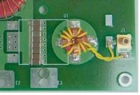
I noticed this and thought you guys might like to know... this is how the big guys (DEI) do it:
They used this setup at 12.2MHz - 14.9MHz to drive special shiny IXYSRF/DEI MOSFETs. Note that it's a 10:1 impedance transformer; 10 turns on the primary, and four parallelled copper straps form the secondary, anchored to concentric rings of copper within the PCB. Mind you, they're only using silly >.< expensive RF FETs.
If I have any time to try this myself, I'd even be tempted to design a set of "sandwich" PCBs which contain the appropriate artwork to commutate both the primary and secondary with the simple addition of copper links through the two boards, corresponding to inside/outside the ferrite toroid. Hmmm. ^^

Re: HF gate drive experiments
Marko, Fri Nov 10 2006, 04:44PM
That's very close to my idea, although I tought to strip-up entire toroid.
I would alsouse HF carbonyl instead of ferrite to lower losses.
What material are those motherboard chokes from (seems to be powder but un-ordinary?)

Marko, Fri Nov 10 2006, 04:44PM
That's very close to my idea, although I tought to strip-up entire toroid.
I would alsouse HF carbonyl instead of ferrite to lower losses.
What material are those motherboard chokes from (seems to be powder but un-ordinary?)

Re: HF gate drive experiments
Steve Conner, Fri Nov 10 2006, 04:50PM
Avalanche: I don't have anything more than what I showed in the first post You guys are all ahead of me now.
Firkragg: if you mean the output filter chokes for the core voltage regulator, they should be hydrogen reduced iron powder. (the low frequency kind of iron powder that's not too good at RF)
Steve Conner, Fri Nov 10 2006, 04:50PM
Avalanche: I don't have anything more than what I showed in the first post
 You guys are all ahead of me now.
Firkragg: if you mean the output filter chokes for the core voltage regulator, they should be hydrogen reduced iron powder. (the low frequency kind of iron powder that's not too good at RF)
Re: HF gate drive experiments
Marko, Fri Nov 10 2006, 07:09PM
Not output filter, but HF buck chokes. They are supposed to work at hundreds of Khz so I tought, if they aren't 'normal' powdered iron, possibly of lower permeability, I wondered how much could they be pushed..
Steve: since you already pwn a quite powerful 27Mhz transmitter you can just try to power a resonator directly.
After you match it properly you can get some sparks from that transmitter ^^
(or, I quess, you don't want to punish it any more?)
Marko, Fri Nov 10 2006, 07:09PM
if you mean the output filter chokes for the core voltage regulator, they should be hydrogen reduced iron powder. (the low frequency kind of iron powder that's not too good at RF)
Not output filter, but HF buck chokes. They are supposed to work at hundreds of Khz so I tought, if they aren't 'normal' powdered iron, possibly of lower permeability, I wondered how much could they be pushed..
Steve: since you already pwn a quite powerful 27Mhz transmitter you can just try to power a resonator directly.
After you match it properly you can get some sparks from that transmitter ^^
(or, I quess, you don't want to punish it any more?)
Re: HF gate drive experiments
Steve Conner, Fri Nov 10 2006, 08:09PM
I already tried powering a neon lamp and a plasma globe off it:

and it didn't seem to like it much :(
Steve Conner, Fri Nov 10 2006, 08:09PM
I already tried powering a neon lamp and a plasma globe off it:

and it didn't seem to like it much :(
Re: HF gate drive experiments
ragnar, Tue Nov 14 2006, 07:07AM
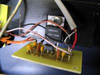
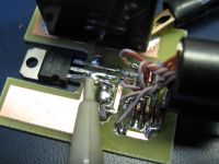
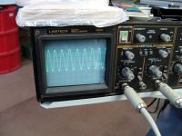
The kind of power I'd be switching through the coil isn't going to be that huge -- I don't need a 400W coil, why use a MOSFET so big to handle that kind of power?
So I dug out my IRF730s, built a proper circuit board with nice bypass caps and divider (for halfbridge), and made a board to hold the IRF730 and my self-DC-biasing circuit.


Re: HF gate drive experiments
..., Tue Nov 14 2006, 07:26AM
and...
Waveforms looks perfect at +12/-7
Are you running class e gate drive, or is that just pure power into the gate? Looking at the board it looks like that latter... Good work!
..., Tue Nov 14 2006, 07:26AM
and...
Waveforms looks perfect at +12/-7

Are you running class e gate drive, or is that just pure power into the gate? Looking at the board it looks like that latter... Good work!
Re: HF gate drive experiments
ragnar, Tue Nov 14 2006, 10:16AM
and...
Waveforms looks perfect at +12/-7
Are you running class e gate drive, or is that just pure power into the gate? Looking at the board it looks like that latter... Good work!
Gate drive is using the single IXDD414 at ~14MHz straight into the ferrite transformer. The IXDD gets much hotter than the FET, so there's work to be done. I can afford to add another turn to the ferrite.
The gate is floating at 4.7V, but the impedance of the floating supply is ~5Kohm. If I lower this to perhaps 1-2Kohm then I think it'll float properly.
Re: HF gate drive experiments
Avalanche, Tue Nov 14 2006, 02:33PM
Nice work
Any thoughts on making the gate drive resonant, that might help with the driver heating (then again it might not).
I copied your biasing circuit thing, but I then decided to add an extra transistor. The current taken from the extra winding on the gate drive transformer is used to provide a tiny regulated (zener) supply, and a pot is used to bias an npn transistor which provides the bias for the mosfet from the regulated +5v rail. This way it's still failsafe if the driver blows up.
I'll have to get back into this, my stuff has been temporarily abandoned
Avalanche, Tue Nov 14 2006, 02:33PM
Nice work

Any thoughts on making the gate drive resonant, that might help with the driver heating (then again it might not).
I copied your biasing circuit thing, but I then decided to add an extra transistor. The current taken from the extra winding on the gate drive transformer is used to provide a tiny regulated (zener) supply, and a pot is used to bias an npn transistor which provides the bias for the mosfet from the regulated +5v rail. This way it's still failsafe if the driver blows up.
I'll have to get back into this, my stuff has been temporarily abandoned

Re: HF gate drive experiments
ragnar, Tue Nov 14 2006, 09:32PM


Mine seemed pretty failsafe, but there's really no guarantee that the gate will discharge properly, except that under DC any charge will short through the inductors.
Steve will remember though my describing my 6.5MHz class-E coil which would run with no gatedrive. The resonant circuit was so finely tuned and of sufficient Q that when gate drive was removed, there was enough leakage/capacitance from the channel that the drain current managed to force the FET on and off... dangerous!!
ragnar, Tue Nov 14 2006, 09:32PM
Avalanche wrote ...
Any thoughts on making the gate drive resonant, that might help with the driver heating (then again it might not).
I can afford to add a bit more inductance, because the IRF730 gate capacitance is on the order of ~700pF, not ~2600pF. I'll make the secondary two turns, and change the primary from two to four or five.. that should reduce the magnetizing current, too.Any thoughts on making the gate drive resonant, that might help with the driver heating (then again it might not).
wrote ...
I copied your biasing circuit thing, but I then decided to add an extra transistor. The current taken from the extra winding on the gate drive transformer is used to provide a tiny regulated (zener) supply, and a pot is used to bias an npn transistor which provides the bias for the mosfet from the regulated +5v rail. This way it's still failsafe if the driver blows up.
Pffft!! Well bahhh, fine. Complicate my circuit. See if I care. I copied your biasing circuit thing, but I then decided to add an extra transistor. The current taken from the extra winding on the gate drive transformer is used to provide a tiny regulated (zener) supply, and a pot is used to bias an npn transistor which provides the bias for the mosfet from the regulated +5v rail. This way it's still failsafe if the driver blows up.


Mine seemed pretty failsafe, but there's really no guarantee that the gate will discharge properly, except that under DC any charge will short through the inductors.
Steve will remember though my describing my 6.5MHz class-E coil which would run with no gatedrive. The resonant circuit was so finely tuned and of sufficient Q that when gate drive was removed, there was enough leakage/capacitance from the channel that the drain current managed to force the FET on and off... dangerous!!
Re: HF gate drive experiments
Avalanche, Tue Nov 14 2006, 10:47PM
lol, sorry, I'm just used to complicating other peoples circuits It's what kept me in employment for a year by making me look like I knew what I was doing, before I got the boot
I don't think it's any more failsafe than your version, I think I just did it so I could adjust the bias when messing around with my driver. Sourcing the bias current from a regulated rail might help with the impedence thing you mentioned, I'm not sure.
No gate drive is pretty impressive I wonder if I'm having a similar 'problem' with my setup. Somehow I'm seeing an unwanted 24Mhz when I put a load on, which probably has something to do with the extra capacitance in series with the gate
Avalanche, Tue Nov 14 2006, 10:47PM
wrote ...
Pffft!! Well bahhh, fine. Complicate my circuit. See if I care.
Pffft!! Well bahhh, fine. Complicate my circuit. See if I care.
lol, sorry, I'm just used to complicating other peoples circuits
 It's what kept me in employment for a year by making me look like I knew what I was doing, before I got the boot
I don't think it's any more failsafe than your version, I think I just did it so I could adjust the bias when messing around with my driver. Sourcing the bias current from a regulated rail might help with the impedence thing you mentioned, I'm not sure.
No gate drive is pretty impressive
 I wonder if I'm having a similar 'problem' with my setup. Somehow I'm seeing an unwanted 24Mhz when I put a load on, which probably has something to do with the extra capacitance in series with the gate
Re: HF gate drive experiments
ragnar, Wed Nov 15 2006, 03:08AM
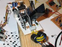
I revised my transformer to use a four-turn primary, two-turn secondary, and single-turn bias winding... and when I connected it back up to the IXDD414 and IRF730, it still runs hot... but I didn't need (or at least, didn't want) to add any extra inductance -- resonance was ~15MHz, and the Q is so low that 13.56MHz is just fine.
The efficiency is a little disappointing, because it draws 980mA at 22V.. but I could justify this saying that, as opposed to driving the IRFP450, I'm getting almost 18V p/p across the gate, I'm driving it "significantly" faster (up to 14MHz not 11.5MHz), or that the IXDD gets less efficient as its load increases, blah blah. It works, and with a 40mm fan, it stays cool enough (hot.), for now.
After mounting the IRF730 to a free heatsink, I wound a little resonator, plonked it on a groundplane, and used my signal generator to find that, tweaking the height of the primary, it works at ~12.7 - 14MHz.
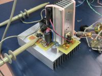
The picture below shows what the combined gatedriver/bias/decoupling/FET looks like.

Re: HF gate drive experiments
..., Wed Nov 15 2006, 05:37AM
Are those some microchip rubber bands I spy
It certainly looks evil....
..., Wed Nov 15 2006, 05:37AM
Are those some microchip rubber bands I spy

It certainly looks evil....
Print this page