
5 MHz CW TC with PLL tracking oscillator
WaveRider, Mon Oct 09 2006, 02:15PMHi all!
Playing around with class-E tesla coils and amplifiers has tempted me to try a tesla coil that "auto tunes" the oscillator using a NE564 PLL. Hence, I present my first prototype using a PLL tuned oscillator for a tesla coil.
Using the NE564 PLL/VCO running at 4 times the resonant frequency , I use two 74LS74 D flip-flops to divide by 4 (so I can get 0 and 90 deg outputs for trimming the feedback phase more easily).
An IXDD414 driver chip is used with a 2SK2698 MOSFET. Further impedance matching and phase correction is achieved with an LC network that feeds the TC primary (sorta like the DRSSTC).
Some details:
1. Secondary: 24m 1.5mm[sup]2[/sup] pvc coated wire on 90mm diam PVC drain pipe.
2. Primary: 10 turns of 1.0mm diam enameled wire close wound on top of secondary as close to the bottom as possible for max magnetic coupling.
3. PLL feedback used antenna (electric field) pickup.
4. Input phase can be adjusted about 45 deg. Another approx 20 deg variation can be had on output adjustment.
5. Typical running frequency at 80-100 watt input: 4.83MHz. Will vary with power as a result of plasma discharge capacitive loading at the top.
Now, some pix:
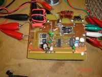
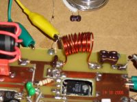
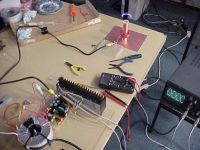
The circuit board with PLL/VCO, frequency dividing flip-flops, MOSFET driver, voltage regulators and power mosfet.
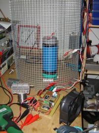
The full setup
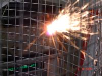
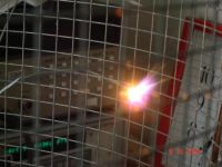
Sparks! Power input is about 75 watts (30 volts in, 2.5 amps). Bright sparks are from zinc coated wire that I used as a topload.
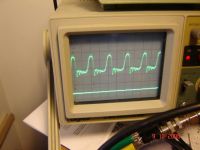
The MOSFET drain waveform (roughly...there is some ringing from the oscilloscope lead..) Peak drain voltage is about 100V with 30V DC input. This depends heavily on the plasma load.
The plasma "flame" is very quiet and very hot. Startup is reliable and immediate. The PLL tracks changes in frequency as the plasma develops (as the PLL tries to keep the phase difference between the antenna pickup and VCO output at 90 deg...the MOSFET amplifier, matching network and input phase control make up the rest of the required 270 deg phase shift for max output power). Fan cooling of the heatsink for the power transistor must be used for reliable CW operation. My plan is to add PWM voltage control to the MOSFET drain circuit to achieve audio modulation... After seeing some of the spectacular audio modulated tesla coils by Steve Conner, EVR, etc., I just have to try it myself.. Comments, assistance, questions welcome!
Schematics simulations and detailed documentation to come soon.
EDIT 20061011
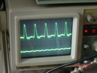
Adding another turn to the matching network inductor, I get something closer to class-E switching operation. The power MOSFET now gets only slightly warm with 200W operation.
Scope shot of Vds
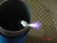
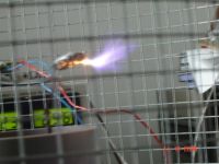
The discharge (could not get close with a ruler to measure...too hot...)
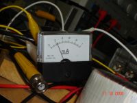
Current meter shows Idd from 100V DC supply.
Bad news!!! I smell smoke!!! Operating at 200W caused my gray PVC drain-pipe coil form to burn... only on the inside!!!??? The plastic must be slightly lossy or I exceeded the breakdown capacity at some point...
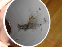
The outside (and coil windings) were unharmed! Sh*t!! I'll have to try a new coil form material (teflon??) or maybe a better quality PVC pipe. For now, I'll rewind the coil on another piece of PVC.
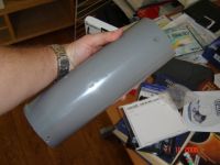
Thankfully, the electronics were not at all harmed. The PLL refused to lock and flames shot out of the top of my PVC coil form along with copious amounts of smoke... Gotta air the place out before the wife returns! What a stink!!!

EDIT 20061120:
In order to reduce the possibility of interference and enhance safety, I mounted the tesla coil driver PCB in a diecast aluminium box.
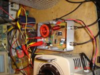
And using some short lengths of RG58U coax to conect to the resonator in the Faraday cage, EMI can be reduced to very low levels. Before using the coax and enclosure for the driver board, there was considerable detectible field (even in other rooms of the house...because of coupling into the power supply). Now, the power supply decoupling seems quite good. The field strength meter barely deflects.
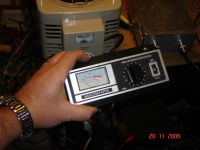
Close to the faraday cage, there is still an evanescent field close to the wire mesh that is readily detectible.
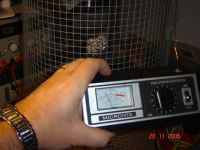
It helps to keep power supply leads and other 'large' metal objects at least 10-20 cm away from the cage in order to minimise coupling to the resonator field.
Here's another spark pic.
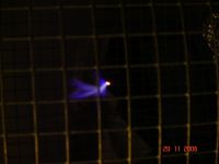
I am presently constructing a PWM modulator based on the TL494 much like the one found on EVR's website.
Hope to have some audio mod working in a few days!!!
Re: 5 MHz CW TC with PLL tracking oscillator
ragnar, Mon Oct 09 2006, 08:57PM
Wow, neato! I bet those IXDD414s are fun =-)
That's what I love about PLL -- you can tweak it so it starts up at one frequency, and then tunes for the corona loading.
Audio modulation is with these reasonably silent coils is very rewarding, and I might mention that a little bit of FM is surprisingly effective so long as you sit on the F > Fres side of the peak and don't modulate too deeply. Although I always found the band of good class-E operation to be very narrow on my coils, there's enough slope to the curve to make frequency modulation worthwhile (and surprisingly easy if one is using a permutation of the 4046 chip)
By the way, if I didn't know better I'd suggest your shunt capacitor looks a wee bit too big; Vds crashing down (discharging into the channel) every cycle..?
When you get round to it, for the sake of audio clarity, try this:
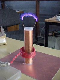
I found an even distribution of corona around the thin copper wire provided a little less volume but greater clarity (of high and low frequencies) than audio reproduced by a plasma from a single point.
If you're looking for a challenge, try running the primary remotely through a metre and a half of coaxial cable. This was one of my challenges for my quadraphonic system -- they all ran from a central control unit, but the 'speakers' could be moved around individually.
Ohh that coax was fun.
ragnar, Mon Oct 09 2006, 08:57PM
Wow, neato! I bet those IXDD414s are fun =-)
That's what I love about PLL -- you can tweak it so it starts up at one frequency, and then tunes for the corona loading.
Audio modulation is with these reasonably silent coils is very rewarding, and I might mention that a little bit of FM is surprisingly effective so long as you sit on the F > Fres side of the peak and don't modulate too deeply. Although I always found the band of good class-E operation to be very narrow on my coils, there's enough slope to the curve to make frequency modulation worthwhile (and surprisingly easy if one is using a permutation of the 4046 chip)
By the way, if I didn't know better I'd suggest your shunt capacitor looks a wee bit too big; Vds crashing down (discharging into the channel) every cycle..?
When you get round to it, for the sake of audio clarity, try this:

I found an even distribution of corona around the thin copper wire provided a little less volume but greater clarity (of high and low frequencies) than audio reproduced by a plasma from a single point.
If you're looking for a challenge, try running the primary remotely through a metre and a half of coaxial cable. This was one of my challenges for my quadraphonic system -- they all ran from a central control unit, but the 'speakers' could be moved around individually.
Ohh that coax was fun.


Re: 5 MHz CW TC with PLL tracking oscillator
Marko, Mon Oct 09 2006, 09:06PM
Yep, cap looks somewhat too big.
Legendary class E operation looks like almost perfect halfwawe-sine, no ringing at bottom as all energy from cap is supposed to be wasted at that time.
With my present class E coil I put the cap few more cm away from mosfet and little ringing showed up at peak of waveform. It doesn't bother me into getting cap closer as it would be difficult, and I'l always have some leakage inductance.
How does your gate waveform look =) ?
One ''extra'' :) question to waverider if I may: If I put a ferrite toroid/bead over both leads (wich are passing close together, current in opposite diretions) can I reduce leakage inductance that way?
Re: 5 MHz CW TC with PLL tracking oscillator
ragnar, Tue Oct 10 2006, 09:29AM
I saw your nice fix in the attachments thread =-)
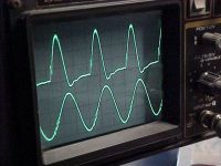
Here are my waveforms (tuned slightly > Fres prior to modulation, hence the overshoot)
Top wave is Vgs, bottom wave is Vprobe-hanging-near-coil
ragnar, Tue Oct 10 2006, 09:29AM
I saw your nice fix in the attachments thread =-)
Here are my waveforms (tuned slightly > Fres prior to modulation, hence the overshoot)
Top wave is Vgs, bottom wave is Vprobe-hanging-near-coil

Re: 5 MHz CW TC with PLL tracking oscillator
WaveRider, Tue Oct 10 2006, 10:26AM
Hi BP, Firkragg
Yes, the drain cap is too big when the coil is run at low power (75 watts, VDD=30V)
Here, I am running the coil at nearly 250W (VDD=115V). The peak voltage is about 250V on the scope. The plasma loading effects reduce the coil input impedance and the matching network behaves more like it should (giving almost class-E operation).
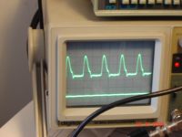
This waveform is already pretty good in that the power mosfet runs relatively cool. Fan cooling of the heatsink is almost not necessary (the driver chip and voltage regs get hotter than the MOSFET). I plan to modify the phase lead network at the PLL sense antenna input. I should be able to "dial up" class-E...I almost can do it now...just need a few more degrees of phase...
Firkragg: A ferrite bead around the primary input leads should not change primary leakage inductance much. A bead on the leads will reduce common mode radiation (ground-loops, power-supply contamination with RF, etc..). In my case, I use an air-core variable capacitor in the matching network to tune out primary leakage inductance. All other capacitors in the matching network are silver-mica type RF caps. They can handle large RF currents without heating up.
An amusing sidenote: I used my normal alligator-clip test leads to connect the air-variable cap across the TC primary.. after 10 seconds, I began to smell overheating vinyl insulation... The leads were overheating badly!! I estimate about 10A of reactive RF current was flowing.. My small test leads could not cope... There's a lesson in this.
  Now I use nice fat leads...
The gate waveform is pretty much a square wave, given that the gate is driven directly by the output of the IXDD414 (a bipolar totem pole circuit). No resonant drive, just a big fat on-off gate signal that resembles (thankfully) the output of the flip-flop Q signal with about 30ns of delay...
BP: I have cooked up a simple PWM circuit with some 555s, a couple of transistors and the usual caps and resistors to get 0-90% duty cycle modulation using a p-ch mosfet. Pulse freq us about 50kHz. The RF amplifier RF choke and decoupling capacitor should comfortably accomodate 15kHz audio bandwidth for modulating the drain circuit. I'll let you know how it goes.
Modulating the frequency of the VCO is not so easy in my case, because the PLL loop bandwidth is about 10 kHz.. Freqs lower than 10kHz would be greatly attenuated because of the PLL trying to correct the frequency.
I believe you when you say that the coax created problems... Improper matching will cause ringing at harmonics of the fundamental as well as transmission line transformer effects which complicate the design of matching networks. Moreover, if PLL tuning is used, phase shifts introduced by transmission line delays must be compensated for if good performance is to be had. Small cables can also introduce losses, reducing spark size, but short runs with good cable shouldn't be very lossy, if system is well matched.
In fact, my first HF coil used a coax feed from my class-E RF amplifier. I used an SWR meter to see when I had a good match (small reflected power). Worked reasonably well, but was a bit bulky and was not well suited to the PLL tuning idea...
EDIT Hi again BP... Just saw your new message. Looks great! You said the top waveform is Vgs... Is this a typo? It looks a lot like Vds..
I love the "fiery loop" pic. Question: With sustained operation, does your secondary begin to heat up a bit (particularly near the base of the coil)? Mine does when I crank it to 250W, but since I used fairly thick gauge windings, it never gets extremely hot...
WaveRider, Tue Oct 10 2006, 10:26AM
Hi BP, Firkragg
Yes, the drain cap is too big when the coil is run at low power (75 watts, VDD=30V)
Here, I am running the coil at nearly 250W (VDD=115V). The peak voltage is about 250V on the scope. The plasma loading effects reduce the coil input impedance and the matching network behaves more like it should (giving almost class-E operation).

This waveform is already pretty good in that the power mosfet runs relatively cool. Fan cooling of the heatsink is almost not necessary (the driver chip and voltage regs get hotter than the MOSFET). I plan to modify the phase lead network at the PLL sense antenna input. I should be able to "dial up" class-E...I almost can do it now...just need a few more degrees of phase...
One ''extra'' :) question to waverider if I may: If I put a ferrite toroid/bead over both leads (wich are passing close together, current in opposite diretions) can I reduce leakage inductance that way?
Firkragg: A ferrite bead around the primary input leads should not change primary leakage inductance much. A bead on the leads will reduce common mode radiation (ground-loops, power-supply contamination with RF, etc..). In my case, I use an air-core variable capacitor in the matching network to tune out primary leakage inductance. All other capacitors in the matching network are silver-mica type RF caps. They can handle large RF currents without heating up.
An amusing sidenote: I used my normal alligator-clip test leads to connect the air-variable cap across the TC primary.. after 10 seconds, I began to smell overheating vinyl insulation... The leads were overheating badly!!
 I estimate about 10A of reactive RF current was flowing.. My small test leads could not cope... There's a lesson in this.
  Now I use nice fat leads...
The gate waveform is pretty much a square wave, given that the gate is driven directly by the output of the IXDD414 (a bipolar totem pole circuit). No resonant drive, just a big fat on-off gate signal that resembles (thankfully) the output of the flip-flop Q signal with about 30ns of delay...
BP: I have cooked up a simple PWM circuit with some 555s, a couple of transistors and the usual caps and resistors to get 0-90% duty cycle modulation using a p-ch mosfet. Pulse freq us about 50kHz. The RF amplifier RF choke and decoupling capacitor should comfortably accomodate 15kHz audio bandwidth for modulating the drain circuit. I'll let you know how it goes.
Modulating the frequency of the VCO is not so easy in my case, because the PLL loop bandwidth is about 10 kHz.. Freqs lower than 10kHz would be greatly attenuated because of the PLL trying to correct the frequency.
I believe you when you say that the coax created problems... Improper matching will cause ringing at harmonics of the fundamental as well as transmission line transformer effects which complicate the design of matching networks. Moreover, if PLL tuning is used, phase shifts introduced by transmission line delays must be compensated for if good performance is to be had. Small cables can also introduce losses, reducing spark size, but short runs with good cable shouldn't be very lossy, if system is well matched.
In fact, my first HF coil used a coax feed from my class-E RF amplifier. I used an SWR meter to see when I had a good match (small reflected power). Worked reasonably well, but was a bit bulky and was not well suited to the PLL tuning idea...
EDIT Hi again BP... Just saw your new message. Looks great! You said the top waveform is Vgs... Is this a typo? It looks a lot like Vds..
I love the "fiery loop" pic. Question: With sustained operation, does your secondary begin to heat up a bit (particularly near the base of the coil)? Mine does when I crank it to 250W, but since I used fairly thick gauge windings, it never gets extremely hot...
Re: 5 MHz CW TC with PLL tracking oscillator
Marko, Tue Oct 10 2006, 12:42PM
Oh, no, I didn't think it for primary, but for leads between mosfet and shunt cap wich seem to cause some extra ringing. I wondered If I can 'couple' them together with a ferrite bead (both of them trough same bead) to kill leakage inductance at that few cm of wires.
(those long leads at top of the pic)
I guess it's not important anyway.
With my coil I got sparks up to about 10cm long with interrupter, and some 6cm in CW, at about 80W input power (power of supply transformer, I don't know for matching and other stuff).
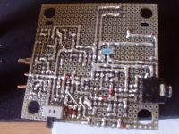
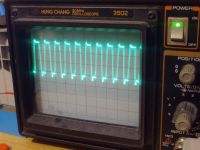
This is how my hard-drive gate waveform looks at 2Mhz.
It could go even faster without the 1 ohm resistor but I don't want to cook the UCC unneedingly.
Single UCC is as close as pssible to mosfet with gate reistor.
Some sparks at unknown <100W (nothing impressive but just for your measure), about 7cm long streamers, coil powered from a triac dimmer.

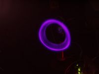
On the right pic you can see the coil sucessfully opening a small portal to another plane of existence, but I had to close it before nasties started coming trough.
Woops, I spammed the thread enough. I guess It's a frustration after my own class E thread got repeatedly ignored
Marko, Tue Oct 10 2006, 12:42PM
A ferrite bead around the primary input leads should not change primary leakage inductance much.
Oh, no, I didn't think it for primary, but for leads between mosfet and shunt cap wich seem to cause some extra ringing. I wondered If I can 'couple' them together with a ferrite bead (both of them trough same bead) to kill leakage inductance at that few cm of wires.
(those long leads at top of the pic)
I guess it's not important anyway.
With my coil I got sparks up to about 10cm long with interrupter, and some 6cm in CW, at about 80W input power (power of supply transformer, I don't know for matching and other stuff).

This is how my hard-drive gate waveform looks at 2Mhz.
It could go even faster without the 1 ohm resistor but I don't want to cook the UCC unneedingly.

Single UCC is as close as pssible to mosfet with gate reistor.
Some sparks at unknown <100W (nothing impressive but just for your measure), about 7cm long streamers, coil powered from a triac dimmer.


On the right pic you can see the coil sucessfully opening a small portal to another plane of existence, but I had to close it before nasties started coming trough.
Woops, I spammed the thread enough. I guess It's a frustration after my own class E thread got repeatedly ignored

Re: 5 MHz CW TC with PLL tracking oscillator
Steve Conner, Tue Oct 10 2006, 01:17PM
Firkragg: I'll let you away with the threadjacking this time, since your pic of the "portal" was neat.
The ferrite bead would increase the common-mode inductance, but it's the differential mode inductance that causes your problem, and the bead won't change this any more than binding the two wires together tightly or shortening then.
Re: 5 MHz CW TC with PLL tracking oscillator
WaveRider, Tue Oct 10 2006, 01:43PM
Firkragg: The ring of fire is great! How did you do it?
I get about 5 cm of fat hot flame with a couple of cms of hairy streamers at the tip with 220W of DC power on the drain. My point-and-click digital camera is not to good with close-ups...nonetheless, I'll try to get a photo with a ruler scale in the picture.. My main interest is in audio mod, not streamer length, tho...
Yeah..SteveC is right. The ferrite bead in your case will not do much. Can you make PCBs? Use a double-sided board with one side unetched (as a ground plane) and put the components on the etched side...RF microstrip style. This cuts trace inductance and reduces radiation and coupling into adjacent conductors massively. (This is what I've done.) With over 200V RF signal in the MOSFET drain, I see a little over 0.1V RF on the power supply rails. This is good for preventing EMI (keeps thos angry hams away!)
Firkragg... I lurked lots in your and BPs Class-E threads. You guys are doing lots of interesting stuff! Sorry for not being more interactive... I've been burdened with lots of work/personal stuff lately. My little bit of free time was spent on "projecting" rather than HV forum posting...sorry for being a bit absent!
WaveRider, Tue Oct 10 2006, 01:43PM
Firkragg: The ring of fire is great! How did you do it?
I get about 5 cm of fat hot flame with a couple of cms of hairy streamers at the tip with 220W of DC power on the drain. My point-and-click digital camera is not to good with close-ups...nonetheless, I'll try to get a photo with a ruler scale in the picture.. My main interest is in audio mod, not streamer length, tho...
Yeah..SteveC is right. The ferrite bead in your case will not do much. Can you make PCBs? Use a double-sided board with one side unetched (as a ground plane) and put the components on the etched side...RF microstrip style. This cuts trace inductance and reduces radiation and coupling into adjacent conductors massively. (This is what I've done.) With over 200V RF signal in the MOSFET drain, I see a little over 0.1V RF on the power supply rails. This is good for preventing EMI (keeps thos angry hams away!)

Firkragg... I lurked lots in your and BPs Class-E threads. You guys are doing lots of interesting stuff! Sorry for not being more interactive... I've been burdened with lots of work/personal stuff lately. My little bit of free time was spent on "projecting" rather than HV forum posting...sorry for being a bit absent!
Re: 5 MHz CW TC with PLL tracking oscillator
Steve Conner, Tue Oct 10 2006, 02:31PM
What were you thinking! The whole point of forums is to use up any free time that you might spend on outdated 20th century pursuits like actually building things.

Steve Conner, Tue Oct 10 2006, 02:31PM
WideRaver wrote ...
My little bit of free time was spent on "projecting" rather than HV forum posting
My little bit of free time was spent on "projecting" rather than HV forum posting
What were you thinking! The whole point of forums is to use up any free time that you might spend on outdated 20th century pursuits like actually building things.


Re: 5 MHz CW TC with PLL tracking oscillator
ragnar, Tue Oct 10 2006, 03:04PM
RiveWader, the ring of fire is an oldie but a goodie -- if you've a secondary made from thin enamelled wire, simply unwind a top turn, power up, and watch him spray around -- noisy... until he melts into a ball, that is. =-)
I've got a couple of good "vortex" pics on my other PC.
For the sake of audio, I found my 6.5MHz coil _aaalmost_ totally silent... not a hissing or spraying noise to be heard anywhere near it... but there was still the slightest 'rippling' noise as the plasma flailed in the air. Multiple discharge points to reduce the size of the plasma (and disturbances from airflow, etc) will also reduce the noise if you can cause them to share the corona load evenly.
The plasma appearance at > 6MHz is just amazing... which is why I'm so keen on getting my 13.56MHz coil going...
**strokes new gatedrivers**
I'm quite close, I'll let you know how it goes. I've found fixed-frequency pursuits to be a rewarding challenge... because then I never have an excuse to complain about retuning all my resonant circuits because I fiddled the freq

Re: 5 MHz CW TC with PLL tracking oscillator
Marko, Tue Oct 10 2006, 06:01PM
Oh, but wasn't that the point..? I'l see what can I do, don't bother with me anymore ^^.
I just taped long enough piece of litz wire to the topload, and curved the very tip of it for some 90 deg.
Wire would spin up and produce such effect...
Marko, Tue Oct 10 2006, 06:01PM
and the bead won't change this any more than binding the two wires together tightly or shortening then.
Oh, but wasn't that the point..?
 I'l see what can I do, don't bother with me anymore ^^.
The ring of fire is great! How did you do it?
I just taped long enough piece of litz wire to the topload, and curved the very tip of it for some 90 deg.
Wire would spin up and produce such effect...
Re: 5 MHz CW TC with PLL tracking oscillator
WaveRider, Tue Oct 10 2006, 07:01PM
BP: Look forward to seeing your 13.56MHz coil in action!! What gate drivers are you using? (UCC37322??)
The IXDD414 is good to about 10MHz. After that, its dissipation (even unloaded) becomes too great. I think there is IXYS sells a version that will work to 30MHz, but I'm not sure...
Thanks for the tips on the "ring of blue fire" and your experiences with audio mod... I'm really happy with the power output of the coil... I will make the PCB layout for the PWM module tomorrow!
Re: 5 MHz CW TC with PLL tracking oscillator
Marko, Tue Oct 10 2006, 07:26PM
Oh, sure, the power of DEIC420
They look like they could work up to 100Mhz with resonant drive, and I don't think you really need such stuff yet if you swich to resonant drive.
Interesting thing was that MAX4422's wich have only MOS output stage worked very poorly compared to UCC's even at frequencies where bipolar output stage should be suffering greatly.
I even blew two due to overloading.
BP and I are using UCC's, now, although I'm not aiming for uber-high frequencies over long sparks yet so I use hard drive.
Marko, Tue Oct 10 2006, 07:26PM
The IXDD414 is good to about 10MHz. After that, its dissipation (even unloaded) becomes too great. I think there is IXYS sells a version that will work to 30MHz, but I'm not sure...
Oh, sure, the power of DEIC420

They look like they could work up to 100Mhz with resonant drive, and I don't think you really need such stuff yet if you swich to resonant drive.
Interesting thing was that MAX4422's wich have only MOS output stage worked very poorly compared to UCC's even at frequencies where bipolar output stage should be suffering greatly.
I even blew two due to overloading.
BP and I are using UCC's, now, although I'm not aiming for uber-high frequencies over long sparks yet so I use hard drive.
Re: 5 MHz CW TC with PLL tracking oscillator
Avalanche, Tue Oct 10 2006, 08:28PM
All this class-e stuff lately has got me working on a 'secret' class-e coil, about 8Mhz. Whether or not it'll ever work is beyond me right now.
Is their any reason the drive into the final MOSFET needs to be a square wave? You could maybe just use ordinary bipolar transistor stages to achieve the various stages of amplification required to drive the final output device, and match it into the gate capacitance of the MOSFET. I would think, that because those big power MOSFETs have such a narrow linear region, you can drive them with a sine wave and maybe bias it if required to the point where you are getting a 50% duty cycle. Or have I lost the plot? In the days of pirate radio rig building, I used to use bog standard 2n3904's at over 100Mhz, so I'm a bit wary of using anything other than bipolar transistors at high frequencies. There are some very nice RF power transistors available, which would probably be fun to play around with in a Tesla coil application. Not cheap though!
For my class-e coil, I'm basically making a powerful transmitter, and base feeding the resonator... is this cheating?

Re: 5 MHz CW TC with PLL tracking oscillator
ragnar, Tue Oct 10 2006, 08:58PM
Base feed isn't cheating, it's novel, and congrats if you ever get it to work. You'll need plenty of volts =-P
Let's be careful not to hijack RiveWader's thread too much...
Do you remember that PDF we read a while ago showing a 45W gatedriver? 3.6nF MOSFET with square-wave drive at 30MHz... yowch! I could do with one of those about now...
Avalanche, biasing the MOSFET is acceptable, so long as you can guarantee that your gatedriver will never fail
If you haven't already read about my uber self-DC-biasing gate-driver and transformer, I'll link you or email you about it. Just ask =-)
I'm about to try out these IXDD414s at highish frequencies, I'll let you know how they go, WaveRider =-)
[edit: so far so good at 12MHz... the edges are a lil slopey, but it appears for now to be holding up... using the same secret technique I used with the UCCs, at least]
ragnar, Tue Oct 10 2006, 08:58PM
Base feed isn't cheating, it's novel, and congrats if you ever get it to work. You'll need plenty of volts =-P
Let's be careful not to hijack RiveWader's thread too much...

wrote ...
BP: Look forward to seeing your 13.56MHz coil in action!! What gate drivers are you using? (UCC37322??)
The UCC37322 chip is part of my gatedriver, but they really only act as a buffer to convert the 5V logic to a slightly lower impedance drive that can swing an IRF510. I'm trying to tweak a transmission line transformer on a binocular core to provide the drive from the IRF510 into a power MOSFET.BP: Look forward to seeing your 13.56MHz coil in action!! What gate drivers are you using? (UCC37322??)
Do you remember that PDF we read a while ago showing a 45W gatedriver? 3.6nF MOSFET with square-wave drive at 30MHz... yowch! I could do with one of those about now...

Avalanche, biasing the MOSFET is acceptable, so long as you can guarantee that your gatedriver will never fail

If you haven't already read about my uber self-DC-biasing gate-driver and transformer, I'll link you or email you about it. Just ask =-)
I'm about to try out these IXDD414s at highish frequencies, I'll let you know how they go, WaveRider =-)
[edit: so far so good at 12MHz... the edges are a lil slopey, but it appears for now to be holding up... using the same secret technique I used with the UCCs, at least]
Re: 5 MHz CW TC with PLL tracking oscillator
Marko, Tue Oct 10 2006, 09:24PM
I's called class C if I get you right.
The problem is acheiving enough power with such bjt's, though.
Not to jack this, I think it's better to move to my or blackplasma's thread already opened in TC's.
Marko, Tue Oct 10 2006, 09:24PM
Is their any reason the drive into the final MOSFET needs to be a square wave? You could maybe just use ordinary bipolar transistor stages to achieve the various stages of amplification required to drive the final output device, and match it into the gate capacitance of the MOSFET. I would think, that because those big power MOSFETs have such a narrow linear region, you can drive them with a sine wave and maybe bias it if required to the point where you are getting a 50% duty cycle.
I's called class C if I get you right.
The problem is acheiving enough power with such bjt's, though.
Not to jack this, I think it's better to move to my or blackplasma's thread already opened in TC's.
Re: 5 MHz CW TC with PLL tracking oscillator
Steve Conner, Tue Oct 10 2006, 09:32PM
Avalanche: Base feeding will work, but the base usually has a rather high impedance, of the order of 1kOhm, while class-E amps like the ones we're using want to see a load of some tens of ohms. This guy successfully did it, but off a vacuum tube oscillator that would have an output impedance of a few K anyway.
You could use a matching network to drive it, but link coupling with a separate primary coil in the classical Tesla style is better, in that it gives a lower Q (hence easier tuning and less losses) for a given impedance step-up ratio. Richie Burnett and I proved this mathematically by accident while we were trying to design a DRSSTC base-fed by an L-match network.
What you said about sine wave drive and multi-stage amplification seems pretty much right.
WaveRider: didn't you experiment with base feeding but find that link coupling worked better?
Steve Conner, Tue Oct 10 2006, 09:32PM
Avalanche: Base feeding will work, but the base usually has a rather high impedance, of the order of 1kOhm, while class-E amps like the ones we're using want to see a load of some tens of ohms. This guy successfully did it, but off a vacuum tube oscillator that would have an output impedance of a few K anyway.

You could use a matching network to drive it, but link coupling with a separate primary coil in the classical Tesla style is better, in that it gives a lower Q (hence easier tuning and less losses) for a given impedance step-up ratio. Richie Burnett and I proved this mathematically by accident while we were trying to design a DRSSTC base-fed by an L-match network.
What you said about sine wave drive and multi-stage amplification seems pretty much right.
WaveRider: didn't you experiment with base feeding but find that link coupling worked better?
Re: 5 MHz CW TC with PLL tracking oscillator
WaveRider, Wed Oct 11 2006, 08:14AM
Yes! That's the one (EUR 31 or so from Digikey)...
SteveC: No, I did not try base feeding because the impedance at the fundamental parallel resonance would be quite high (as you mentioned). The losses incurred in any base-connected impedance transformer going from 10-15 ohms to 1000 ohms or so would likely be quite high. Also, it is more difficult to control the coupling. Inductive coupling at the base using a few turns worked far better (at least in simulation). I should think about it some more before saying anything else.... By adding or removing primary loops, I could actually get a match to a 50 ohm system at various power levels. (Lower power, less plasma loading, fewer primary turns....i.e. real part of primary input impedance decreases as the "flame" gets bigger at the top of the coil...)
Avalanche: RF power MOSFETS are used all over the place up to a few GHz (in mobile telephone base stations, broadcast transmitters, etc.) They are indeed pricey, tho'.. Unlike the MOSFETS we are using here (with "lossy" polysilicon gates) RF MOSFETS use metal gates.
WaveRider, Wed Oct 11 2006, 08:14AM
Oh, sure, the power of DEIC420
Yes! That's the one (EUR 31 or so from Digikey)...
SteveC: No, I did not try base feeding because the impedance at the fundamental parallel resonance would be quite high (as you mentioned). The losses incurred in any base-connected impedance transformer going from 10-15 ohms to 1000 ohms or so would likely be quite high. Also, it is more difficult to control the coupling. Inductive coupling at the base using a few turns worked far better (at least in simulation). I should think about it some more before saying anything else....
 By adding or removing primary loops, I could actually get a match to a 50 ohm system at various power levels. (Lower power, less plasma loading, fewer primary turns....i.e. real part of primary input impedance decreases as the "flame" gets bigger at the top of the coil...)
Avalanche: RF power MOSFETS are used all over the place up to a few GHz (in mobile telephone base stations, broadcast transmitters, etc.) They are indeed pricey, tho'.. Unlike the MOSFETS we are using here (with "lossy" polysilicon gates) RF MOSFETS use metal gates.
Re: 5 MHz CW TC with PLL tracking oscillator
WaveRider, Fri Oct 13 2006, 01:11PM
Hi all,
Added some extra info to this webpage. Posted the schematic for your perusal as well as some thoughts. No mathematics or heavy theory.....yet (MMMwwaahhhhahahahah!)
WaveRider, Fri Oct 13 2006, 01:11PM
Hi all,
Added some extra info to this webpage. Posted the schematic for your perusal as well as some thoughts. No mathematics or heavy theory.....yet (MMMwwaahhhhahahahah!)

Re: 5 MHz CW TC with PLL tracking oscillator
WaveRider, Wed Oct 18 2006, 05:15PM
News: Just broke 300W on a single 2SK2698 MOSFET.. (After sacrificing a couple to the god of blue smoke.. ) Rewinding my coil after my plastic tube coilform met a firey end meant sacrificing a turn or two.. Hence, the resonant frequency shifted somewhat.. Would not function properly until I lowered the resonant frequency using a small alu foil topload. This had the unexpected desireable effect of givind a better match to the output of the final amplifier... Now I get stable, efficient, almost class-E operation over a fair range of operating powers..
Also, added some simulation results to my PLL Tesla Coil page. basically I used NEC (an antenna solver) to study the effects of winding loss in a tesla coil resonator. Even small losses can have a strong effect, particularly in CW coils operating at "high" powers. No attempt has been made at modeling the arc, yet... (Perhaps a new thread??)
WaveRider, Wed Oct 18 2006, 05:15PM
News: Just broke 300W on a single 2SK2698 MOSFET.. (After sacrificing a couple to the god of blue smoke..
 ) Rewinding my coil after my plastic tube coilform met a firey end meant sacrificing a turn or two.. Hence, the resonant frequency shifted somewhat.. Would not function properly until I lowered the resonant frequency using a small alu foil topload. This had the unexpected desireable effect of givind a better match to the output of the final amplifier... Now I get stable, efficient, almost class-E operation over a fair range of operating powers..
 Also, added some simulation results to my PLL Tesla Coil page. basically I used NEC (an antenna solver) to study the effects of winding loss in a tesla coil resonator. Even small losses can have a strong effect, particularly in CW coils operating at "high" powers. No attempt has been made at modeling the arc, yet... (Perhaps a new thread??)
Re: 5 MHz CW TC with PLL tracking oscillator
Marko, Wed Oct 18 2006, 05:37PM
The worst 'drawback' of class E I found is it's sensitivity to change in load impedance (and reactance).
If I didn't let out a breakout on my little coil topload peak coltage would become enormous and coil would start drawing insane currents, burning most of power on the mosfet due to mismatch (heavy over-dampness). I would have to drastiically retune the coupling to make coil work like that and then I would get puny output with breakout point.
Winding HF coils like 'normal' coils probably isn't best practice at all (I had over 1k unloaded impedance), but that's what we got...
Re: 5 MHz CW TC with PLL tracking oscillator
WaveRider, Fri Oct 20 2006, 09:49AM
Hi Firkragg! 1k input impedance should not create problems, unless you risk "overvolting" your MOSFET. (BTW-how did you measure the impedance?) The problem is if you happen to start up near the series resonant frequency of the coupled coil...and particularly if your MOSFET is seeing a capacitive load reactance (which switching circuits do not like very much).
Large currents will result. (I've smoked a few MOSFETs verifying this theory! )
)
I've done some computations using a rigorous model that indicate that the highest fields are attained at the top of your coil between the series and parallel resonances. At the peak voltage point, the primary feedpoint will likely exhibit a fair bit of capacitive reactance...which, for the health of your MOSFET switch, is best to tune out using a matching network. See the bottom of my PLL tesla coil page where I try to continually add stuff..... (I couldn't resist giving my coil a name from Norse mythology...given the trend here at 4HV! )
)
WaveRider, Fri Oct 20 2006, 09:49AM
Hi Firkragg! 1k input impedance should not create problems, unless you risk "overvolting" your MOSFET. (BTW-how did you measure the impedance?) The problem is if you happen to start up near the series resonant frequency of the coupled coil...and particularly if your MOSFET is seeing a capacitive load reactance (which switching circuits do not like very much).
Large currents will result. (I've smoked a few MOSFETs verifying this theory!
 )
)I've done some computations using a rigorous model that indicate that the highest fields are attained at the top of your coil between the series and parallel resonances. At the peak voltage point, the primary feedpoint will likely exhibit a fair bit of capacitive reactance...which, for the health of your MOSFET switch, is best to tune out using a matching network. See the bottom of my PLL tesla coil page where I try to continually add stuff..... (I couldn't resist giving my coil a name from Norse mythology...given the trend here at 4HV!
 )
)Re: 5 MHz CW TC with PLL tracking oscillator
Marko, Fri Oct 20 2006, 11:26AM
Unloaded impedance isn't measured, just roughly estimated using DC resistance and skin depth at my operating frequency.
I don't know wha is the real impedance when coil is loaded with CW spark though..
Too high impedance is always bad (bad Q factor = lower voltage rise, lots of heating in the secondary, etc).
I would just run it up with PLL and it would work unless I detune from class E (thn mosfet dies from overheating).
You can see more pix of the coil (with new secondary) here

Re: 5 MHz CW TC with PLL tracking oscillator
WaveRider, Fri Oct 20 2006, 12:15PM
How can you compute impedance from skin depth and dc resistance for a non-arcing coil? (Skin depth can give you the AC surface resistance of the windings, but nothing else..) You are modeling an inductively coupled resonant circuit.
If the input impedance is dominated by inductance (just below the parallel resonance), little current is drawn from the DC supply... If, on the other hand, you excite the series resonance, the low feedpoint impedance can cause excessive current to flow in the MOSFET drain...thereby smoking it. Somewhere in between generates the highest voltage in the coil.. I discuss in my PLL Tesla coil page that it seems that the "maximum spark" is obtained where the feedpoint impedance exhibits significant capacitive reactance (which puts strain on switching elements). Of course, the loading of the primary with any capacitance (MOSFET drain capacitance, parallel drain capacitor, for example) causes more capacitive reactance to appear as well as introducing a second resonance that can possibly kill mosfets.. I am putting together some computations that show the effects of this..
To stabilise things, some series inductance seems to be needed in the primary circuit.. As you see in my driver circuit, a variable parallel capacitance can be used in conjunction with a bit of extra series inductance to adjust for ideal match while the all-pass phase shift network can correct phase errors introduced by the matching network. I can freely dial up class E or class C operation and anywhere in between..
Re: 5 MHz CW TC with PLL tracking oscillator
Marko, Fri Oct 20 2006, 08:41PM
Oh, stupid me ^
I see I nowhere mentioned that I used prsimary itself as a charging 'choke' instead of separate class E stage.
With big enogh decoupling cap it seems to work just as well.
AFAIK (sccording to r. burnett) when coil is tuned into resonance it's unloaded base impedance *is* just the AC resistance of windings, and it grows bigger when sparks load the coil.
I never had any serious 'out-of-tune' problems since coil seems to draw relatively little current no matter if it is higher or lower than resonance.
The 'capacitiveness' thing you are mentioning doesn't seem to be a problem at all as capacitance is very small and I don't think it will look like soemthing more than few hundred pf on the mosfet.
When I decide approximate number of primary turns the fun begins - lots of moving up-down and changing number of turns, until best mach and nicest class E waveform is acheived.
(toast for a 'scientific' approach ^^)
Re: 5 MHz CW TC with PLL tracking oscillator
WaveRider, Sat Oct 21 2006, 09:17AM
Yours is a perfectly good way to handle the coupling problem. As the coupling goes down, the capacitance effect decreases (as primary self-inductance begins to dominate). I designed my matching circuit as an attempt to transfer maximum power to the secondary while maintaining something close to class-E transistor switching (using a variable capacitor to vary the primary coupling). It seems to work... Yesterday, I ran the coil for two hours. The transistor was barely warm to the touch (I was using fan cooling.) The base of my coil did get a little bit warm, tho' not enough to hurt the PVC insulation or coil form...
WaveRider, Sat Oct 21 2006, 09:17AM
Oh, stupid me ^I figured I was missing a bit of info..
I see I nowhere mentioned that I used prsimary itself as a charging 'choke' instead of separate class E stage.
You are quite right...as long as we are talking about series-like resonance. Add in the effect of the coupling (primary) coil on secondary resonant frequencies and things become more complicated ..even more when we add capacitors/inductors to the primary circuit..
AFAIK (sccording to r. burnett) when coil is tuned into resonance it's unloaded base impedance *is* just the AC resistance of windings, and it grows bigger when sparks load the coil.
The effect I am describing may or may not be a problem... Depends on many things (coupling, losses and loading, etc.) I just found it interesting to model and discover that the max voltage at the top of the coil may not necessarily occur at the "resonant" frequencies seen at the primary coil input terminals.
I never had any serious 'out-of-tune' problems since coil seems to draw relatively little current no matter if it is higher or lower than resonance.
The 'capacitiveness' thing you are mentioning doesn't seem to be a problem at all as capacitance is very small and I don't think it will look like soemthing more than few hundred pf on the mosfet.
When I decide approximate number of primary turns the fun begins - lots of moving up-down and changing number of turns, until best mach and nicest class E waveform is acheived.
(toast for a 'scientific' approach ^^)
Yours is a perfectly good way to handle the coupling problem. As the coupling goes down, the capacitance effect decreases (as primary self-inductance begins to dominate). I designed my matching circuit as an attempt to transfer maximum power to the secondary while maintaining something close to class-E transistor switching (using a variable capacitor to vary the primary coupling). It seems to work... Yesterday, I ran the coil for two hours. The transistor was barely warm to the touch (I was using fan cooling.) The base of my coil did get a little bit warm, tho' not enough to hurt the PVC insulation or coil form...
Re: 5 MHz CW TC with PLL tracking oscillator
Marko, Sat Oct 21 2006, 11:52AM
It's a base impedance, considered when secondary is unloaded and without the primary mess.
The base of your coil is getting warm because secondary is coupling capacitively to primary, causing heavy dielectric losses in PVC.
I melted the base of my first secondary that way, so I use a wide former-less primary wich is set higher to keep coupling same.
Marko, Sat Oct 21 2006, 11:52AM
You are quite right...as long as we are talking about series-like resonance. Add in the effect of the coupling (primary) coil on secondary resonant frequencies and things become more complicated ..even more when we add capacitors/inductors to the primary circuit..
It's a base impedance, considered when secondary is unloaded and without the primary mess.
The base of your coil is getting warm because secondary is coupling capacitively to primary, causing heavy dielectric losses in PVC.
I melted the base of my first secondary that way, so I use a wide former-less primary wich is set higher to keep coupling same.
Re: 5 MHz CW TC with PLL tracking oscillator
ragnar, Sun Oct 22 2006, 01:49AM
The base of my secondary gets hottest regardless of where the primary is. =P
It's probably something to do with that big copper plate I put there.

ragnar, Sun Oct 22 2006, 01:49AM
The base of my secondary gets hottest regardless of where the primary is. =P
It's probably something to do with that big copper plate I put there.


Re: 5 MHz CW TC with PLL tracking oscillator
WaveRider, Mon Oct 23 2006, 07:20AM
Hi Firkragg and "balsamplack"
The lower windings of the coil get hot because the current near the base of the coil is maximum (can be amps to 10s of amps depending on power level, loading, etc..)
These HF coils behave a lot like a 1/4 wave transmission line which is open at the end and shorted at the other. Current is high at the shorted end (where the coil is connected to a "ground-plane" or faraday cage) and voltage is high at the open end..
I did some simulations here when I was attempting to get my Royer/Armstrong coils to work. (The primary geometry is a little bit different, but the resonator behaviour should be the same..) This plot shows the normalised coil current along the helix for a coil with no topload and the primary wound right at the base. It is highest at the base (0m) and small at the top (25m), therefore copper (ohmic) losses from the current are highest here...so the base gets hot!
WaveRider, Mon Oct 23 2006, 07:20AM
Hi Firkragg and "balsamplack"

The lower windings of the coil get hot because the current near the base of the coil is maximum (can be amps to 10s of amps depending on power level, loading, etc..)
These HF coils behave a lot like a 1/4 wave transmission line which is open at the end and shorted at the other. Current is high at the shorted end (where the coil is connected to a "ground-plane" or faraday cage) and voltage is high at the open end..
I did some simulations here when I was attempting to get my Royer/Armstrong coils to work. (The primary geometry is a little bit different, but the resonator behaviour should be the same..) This plot shows the normalised coil current along the helix for a coil with no topload and the primary wound right at the base. It is highest at the base (0m) and small at the top (25m), therefore copper (ohmic) losses from the current are highest here...so the base gets hot!
Re: 5 MHz CW TC with PLL tracking oscillator
WaveRider, Mon Nov 20 2006, 02:20PM
I have updated the original post with some field measurements after installing the driver board in an RF tight box.
I'm working on an audio-mod board. The circuit is based on the TL494 (similar to EVRs Plasmatronic driver).
Also, I have made some minor modifications to the PLL/driver circuit. I will post these to my web site in a couple of days.
Re: 5 MHz CW TC with PLL tracking oscillator
WaveRider, Tue Nov 28 2006, 11:58AM
I have completed the audio modulator! It works well. The arc delivers a crystal-clear rendition of Tim O'Briens "Fiddler's Dream.."

Enjoy!
I will attempt to put together some "How I did it" documentation as soon as possible...
WaveRider, Tue Nov 28 2006, 11:58AM
I have completed the audio modulator! It works well. The arc delivers a crystal-clear rendition of Tim O'Briens "Fiddler's Dream.."

Enjoy!
I will attempt to put together some "How I did it" documentation as soon as possible...
Re: 5 MHz CW TC with PLL tracking oscillator
ragnar, Tue Nov 28 2006, 12:15PM
Beautiful work, WaveRider!
It looks and sounds a lot like my quadraphonic system. The cage I'm sure much reduces its susceptibility to nearby metal objects/sheet, interference with the driver circuitry, fingers, hands, hair etc! =D
I'm keen to hear about your modulator. This is what I'm hoping to pull off with my 13.56MHz coil -- a suitably 'fixed' drive frequency (i.e. +/- a few%) and a class-G/class-H modulator.
Suggestion, if you get the chance -- consider an electrode geometry that causes the discharge to fan out.
Re: 5 MHz CW TC with PLL tracking oscillator
WaveRider, Tue Nov 28 2006, 02:36PM
Hi BP,
Thanks for the kudos!
My modulator is simple... (Valve am transmitter enthusiasts would recognise it as a solid state version of "plate modulation") I will post the prototype schematic when I get the chance to make a presentable drawing, but in words: It's a push-pull DC-DC converter that utilises the PWM capability of the TL494 chip. It operates at 100kHz and uses a ferrite core transformar and ultra-fast rectifiers. Care must be taken to not use filter caps that are too large...in order to avoid excessive high-frequency audio roilloff. Like EVR's Plasmatronic, I modulate the "dead time" of the pulse waveform to modulate the output voltage...which is fed to the drain of the power amplifier stage of my PLL-based class-e TC. Even given the "point" nature of the arc, the sound is loud and clear. Modulation is only about 20% or so.... (It's being driven by my MP3 player... Measly output signal is in no danger of overmodulating the thing! )
)
There are ways to improve the modulator, but I am pretty pleased with this prototype... The sound is better than I imagined it would be given the simplicity of the circuit!
WaveRider, Tue Nov 28 2006, 02:36PM
Hi BP,
Thanks for the kudos!
My modulator is simple... (Valve am transmitter enthusiasts would recognise it as a solid state version of "plate modulation") I will post the prototype schematic when I get the chance to make a presentable drawing, but in words: It's a push-pull DC-DC converter that utilises the PWM capability of the TL494 chip. It operates at 100kHz and uses a ferrite core transformar and ultra-fast rectifiers. Care must be taken to not use filter caps that are too large...in order to avoid excessive high-frequency audio roilloff. Like EVR's Plasmatronic, I modulate the "dead time" of the pulse waveform to modulate the output voltage...which is fed to the drain of the power amplifier stage of my PLL-based class-e TC. Even given the "point" nature of the arc, the sound is loud and clear. Modulation is only about 20% or so.... (It's being driven by my MP3 player... Measly output signal is in no danger of overmodulating the thing!
 )
)There are ways to improve the modulator, but I am pretty pleased with this prototype... The sound is better than I imagined it would be given the simplicity of the circuit!
Re: 5 MHz CW TC with PLL tracking oscillator
..., Tue Nov 28 2006, 03:19PM
Wow That is really good!
Do you have any way to test the quiet and max modulation output? I would have imagined that with such a small amount spark it would be hard to get a decen't listening level...
..., Tue Nov 28 2006, 03:19PM
Wow
 That is really good!
Do you have any way to test the quiet and max modulation output? I would have imagined that with such a small amount spark it would be hard to get a decen't listening level...
Re: 5 MHz CW TC with PLL tracking oscillator
ragnar, Tue Nov 28 2006, 09:55PM
The amplitude of sound you can get from a given 'volume' of plasma is often surprising. With my four ~4MHz coils I had to modulate quite deep to make it suitably audible amongst, e.g. people talking.
WaveRider's spark isn't all that 'small' either =)
ragnar, Tue Nov 28 2006, 09:55PM
The amplitude of sound you can get from a given 'volume' of plasma is often surprising. With my four ~4MHz coils I had to modulate quite deep to make it suitably audible amongst, e.g. people talking.
WaveRider's spark isn't all that 'small' either =)
Re: 5 MHz CW TC with PLL tracking oscillator
..., Tue Nov 28 2006, 11:21PM
I always imagined you needed the huge sparkage like on EVR's PlasmaSonic system. I tried making a small '494 based coil and even with 1" sparks (a lot of them) I couldn't get usable sound before it started to clip.
..., Tue Nov 28 2006, 11:21PM
I always imagined you needed the huge sparkage like on EVR's PlasmaSonic system. I tried making a small '494 based coil and even with 1" sparks (a lot of them) I couldn't get usable sound before it started to clip.
Re: 5 MHz CW TC with PLL tracking oscillator
WaveRider, Thu Nov 30 2006, 02:25PM
The spark is not huge, but it can be a few cms long. Remember, the coil is not operating at full power when being audio modulated. It runs somewhere near 60-75%. The sound is very clear and quite loud. The MP3 player clips before the coil does, so I need a better audio source to test the full range..
I have updated my PLL tesla coil page with the circuit that I used for the modulator. I don't think I made any errors in the schematic.. If you build this circuit, be sure ti use good low-loss capacitors in the 100V transformer circuit.
Re: 5 MHz CW TC with PLL tracking oscillator
WaveRider, Fri Jan 19 2007, 03:08PM
Hi all,
Sorry about the silence, but I have not been able to spend much time "projecting" lately. However, I have been taking little snapshots of free time to prepare a first draft of some detailed notes on my Class-E audio modulated coil. They can be found on my PLL Tesla page. Hope it is informative... I welcome any comments/questions on how to improve the presentation or correct errors.. Also, to those experienced people: I put in lots of warnings to discourage those who may attempt construction without understanding the dangers. Please do not be put off by my overcautiousness.
Cheers and enjoy..
Re: 5 MHz CW TC with PLL tracking oscillator
ragnar, Fri Jan 19 2007, 03:46PM
hi Bill,
glad to know you're alright -- and cheers for the progress on your page. **reads carefully**
I've been talking to Steve about some of the quirks I encounter with high-frequency class-E setups, and I'm documenting them, along with how I got around them -- the problems (and the solutions) are definitely not obvious (at least not to me!) at first. I decided to grow a spine and stop being a pussy, and I made a proper flywheel circuit to couple the resonator the the drain/RFC. I also invested in some air-dielectric variable caps (which I've been meaning to do for a while for other projects); it's really a pain switching combinations of these 250pF 10kV ceramics in and out for effect.
Some of the issues I was confronted with:
-- If drive duty cycle is even just smidgin > 50%, the whole output circuit crashes with no explanation,
-- gatedrive from 9V-11V is fine... as I drive it to 12V-15V, less and less happens on the output until no power flows,
-- device's own output plus forgotten capacitance between the drain tab, e.g. silicone pad, and heatsink sometimes exceeds desirable shunt capacitance; no matter how little extra capacitance you add, it'll always be too much! As a ballpark figure, my particular silicone pads yield about 40pF capacitance between the drain tab and a heatsink.
-- triple/quadruple check that resonator is actually being driven at fundamental! Inspecting waveforms whilst driving at harmonics often gives the (wrong) impression that parts of the circuit are working
-- even a little stray inductance between the shunt capacitor and the switching device can ruin things at high frequencies; I've found it much better to connect the cap to the drain tab, rather than the drain pin or even an inch away on the PCB.
I'm not sure how much of this applies, but at 13.56MHz, I feels like I'm working with a totally different beast. Then again, that may just be the feeling of inexperience!
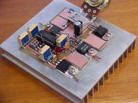
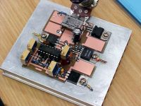
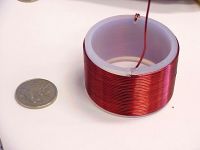
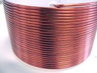
I've attached some pics, including
-- high frequency gate driver transformer techniques,
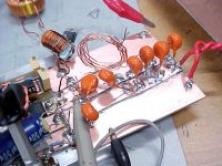
-- (what I pretend is a) good RF PCB layout,
-- more durable secondary wound around teflon PFA former (coin is approx one inch diameter),
-- my very ugly, very lossy "output board" (better than none at all!)
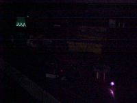
-- whole setup as seen in the dark (highlights are scope, power supply and breakout),
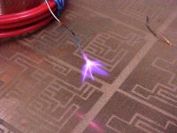
-- closeup of breakout (moire effects on camera are from CCD susceptibility to electric field?),
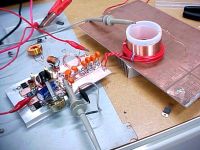
-- driver, output stage, resonator and groundplane all framed,
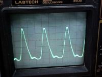
-- some not-too-bad drain-source voltage waveforms (but my 20MHz oscilloscope is probably lying),
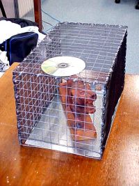
-- EM-shielding cage which I will soon put to use (CD is for scale, Tiger is for effect)
Enjoy =)

ragnar, Fri Jan 19 2007, 03:46PM
hi Bill,
glad to know you're alright -- and cheers for the progress on your page. **reads carefully**
I've been talking to Steve about some of the quirks I encounter with high-frequency class-E setups, and I'm documenting them, along with how I got around them -- the problems (and the solutions) are definitely not obvious (at least not to me!) at first. I decided to grow a spine and stop being a pussy, and I made a proper flywheel circuit to couple the resonator the the drain/RFC. I also invested in some air-dielectric variable caps (which I've been meaning to do for a while for other projects); it's really a pain switching combinations of these 250pF 10kV ceramics in and out for effect.
Some of the issues I was confronted with:
-- If drive duty cycle is even just smidgin > 50%, the whole output circuit crashes with no explanation,
-- gatedrive from 9V-11V is fine... as I drive it to 12V-15V, less and less happens on the output until no power flows,
-- device's own output plus forgotten capacitance between the drain tab, e.g. silicone pad, and heatsink sometimes exceeds desirable shunt capacitance; no matter how little extra capacitance you add, it'll always be too much! As a ballpark figure, my particular silicone pads yield about 40pF capacitance between the drain tab and a heatsink.
-- triple/quadruple check that resonator is actually being driven at fundamental! Inspecting waveforms whilst driving at harmonics often gives the (wrong) impression that parts of the circuit are working
-- even a little stray inductance between the shunt capacitor and the switching device can ruin things at high frequencies; I've found it much better to connect the cap to the drain tab, rather than the drain pin or even an inch away on the PCB.
I'm not sure how much of this applies, but at 13.56MHz, I feels like I'm working with a totally different beast. Then again, that may just be the feeling of inexperience!

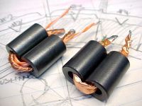
I've attached some pics, including
-- high frequency gate driver transformer techniques,
-- (what I pretend is a) good RF PCB layout,
-- more durable secondary wound around teflon PFA former (coin is approx one inch diameter),
-- my very ugly, very lossy "output board" (better than none at all!)
-- whole setup as seen in the dark (highlights are scope, power supply and breakout),
-- closeup of breakout (moire effects on camera are from CCD susceptibility to electric field?),
-- driver, output stage, resonator and groundplane all framed,
-- some not-too-bad drain-source voltage waveforms (but my 20MHz oscilloscope is probably lying),
-- EM-shielding cage which I will soon put to use (CD is for scale, Tiger is for effect)
Enjoy =)


Re: 5 MHz CW TC with PLL tracking oscillator
..., Sat Jan 20 2007, 01:36AM
good stuff Matt!
One advantage for going with the 13.56mhz is that the resonator is nice and small I can't imagine what that would look like with a couple kw being pumped into it...
I wonder what would happen if you bought some commercial piece of gear that runs at 13.56mhz (plasma etcher?) and added a resonator to it...
..., Sat Jan 20 2007, 01:36AM
good stuff Matt!
One advantage for going with the 13.56mhz is that the resonator is nice and small
 I can't imagine what that would look like with a couple kw being pumped into it...
I wonder what would happen if you bought some commercial piece of gear that runs at 13.56mhz (plasma etcher?) and added a resonator to it...

Re: 5 MHz CW TC with PLL tracking oscillator
WaveRider, Sat Jan 20 2007, 12:16PM
Hi Matt,
Thanks for the concern.. I'm still around, just a little quiet these days..
I'm not sure about this one, but it could be a problem with saturation of the gate drive transformer cores. I would need to know more about your gate-drive setup.
With careful design of the matching network, you should be able to tune this out. In my opinion, this is a classic impedance matching problem and must be viewed as such. Give me more details and perhaps I can help you out.. (e.g. DC load line of PA transistor, resonator geometry, etc.)
It helps to look at each stage separately. That's why I designed the PLL, amplifier, and resonator as separate system elements. I think it makes things easier to stick together in this case.
Again, I would need to know more about your circuit. Also, your 20MHz scope is not likely to show the true waveform very well. However, if you see a stong waveform at 13.56MHz, it is likely that the fundamental resonance is the dominant one.
Ahhh! You have discovered part of the black art of RF engineering. KISS! Keep it short stupid!! Other rules include: always use good ground planes as the earth reference, always decouple all power supplies, no flying leads, use PCB traces backed with a groundplane wherever possible,
component leads as short as possible (surface mount is even better), watch out for inadvertent unwanted feedback by parasitic coupling (use shields around snsitive circuits), everything in a good RF-tight enclosure......
Also, 10kV ceramic caps might be a bit of overkill... Voltage on the primary should never be more than 300-400V or so...
In fact, your board backed with the heat sink looks very neat and clean, as a good RF board should be. The heatsink should be the earth reference (tied to the copper on the back of your PCB).
Perhaps we should move this to another more suitable thread. I am very interested in continuing this discussion given a bit more information about your circuit. We could do some simulations and try to design a proper matching circuit.
Keep up the good work!!!
WaveRider, Sat Jan 20 2007, 12:16PM
Hi Matt,
Thanks for the concern.. I'm still around, just a little quiet these days..

wrote ...
-- If drive duty cycle is even just smidgin > 50%, the whole output circuit crashes with no explanation,
At 13.56MHz, things do indeed become more difficult. Even around 5MHz,you ned to take some care with layout and connections. Certainly, if the switching duty cycle is >50%, you are likely to get high (possibly destructive) drain currents. Class-E switching is always less than 50% duty cycle...-- If drive duty cycle is even just smidgin > 50%, the whole output circuit crashes with no explanation,
wrote ...
-- gatedrive from 9V-11V is fine... as I drive it to 12V-15V, less and less happens on the output until no power flows,
-- gatedrive from 9V-11V is fine... as I drive it to 12V-15V, less and less happens on the output until no power flows,
I'm not sure about this one, but it could be a problem with saturation of the gate drive transformer cores. I would need to know more about your gate-drive setup.
wrote ...
-- device's own output plus forgotten capacitance between the drain tab, e.g. silicone pad, and heatsink sometimes exceeds desirable shunt capacitance; no matter how little extra capacitance you add, it'll always be too much! As a ballpark figure, my particular silicone pads yield about 40pF capacitance between the drain tab and a heatsink.
-- device's own output plus forgotten capacitance between the drain tab, e.g. silicone pad, and heatsink sometimes exceeds desirable shunt capacitance; no matter how little extra capacitance you add, it'll always be too much! As a ballpark figure, my particular silicone pads yield about 40pF capacitance between the drain tab and a heatsink.
With careful design of the matching network, you should be able to tune this out. In my opinion, this is a classic impedance matching problem and must be viewed as such. Give me more details and perhaps I can help you out.. (e.g. DC load line of PA transistor, resonator geometry, etc.)
It helps to look at each stage separately. That's why I designed the PLL, amplifier, and resonator as separate system elements. I think it makes things easier to stick together in this case.
wrote ...
-- triple/quadruple check that resonator is actually being driven at fundamental! Inspecting waveforms whilst driving at harmonics often gives the (wrong) impression that parts of the circuit are working
-- triple/quadruple check that resonator is actually being driven at fundamental! Inspecting waveforms whilst driving at harmonics often gives the (wrong) impression that parts of the circuit are working
Again, I would need to know more about your circuit. Also, your 20MHz scope is not likely to show the true waveform very well. However, if you see a stong waveform at 13.56MHz, it is likely that the fundamental resonance is the dominant one.
wrote ...
-- even a little stray inductance between the shunt capacitor and the switching device can ruin things at high frequencies; I've found it much better to connect the cap to the drain tab, rather than the drain pin or even an inch away on the PCB.
-- even a little stray inductance between the shunt capacitor and the switching device can ruin things at high frequencies; I've found it much better to connect the cap to the drain tab, rather than the drain pin or even an inch away on the PCB.
Ahhh! You have discovered part of the black art of RF engineering. KISS! Keep it short stupid!!
 Other rules include: always use good ground planes as the earth reference, always decouple all power supplies, no flying leads, use PCB traces backed with a groundplane wherever possible,
 component leads as short as possible (surface mount is even better), watch out for inadvertent unwanted feedback by parasitic coupling (use shields around snsitive circuits), everything in a good RF-tight enclosure......
Also, 10kV ceramic caps might be a bit of overkill... Voltage on the primary should never be more than 300-400V or so...
In fact, your board backed with the heat sink looks very neat and clean, as a good RF board should be. The heatsink should be the earth reference (tied to the copper on the back of your PCB).
Perhaps we should move this to another more suitable thread. I am very interested in continuing this discussion given a bit more information about your circuit. We could do some simulations and try to design a proper matching circuit.
Keep up the good work!!!
Print this page