
COIN SHRINKING: in a B-field of improved uniformity
Signification, Fri Feb 27 2015, 06:29AMWhile working with inductor design for the critical current damping of very large Xe flashlamps, the subject came up of the strength of the magnetic field generated inside a coil by a large current pulse.
Here is a sample of the discussion of what form the B-field would take under increasingly large parameters (current, coil thickness, etc.)
...clip...from the 'other' guy...
"" And yes, I agree with you that the maximum will be on a ring around
the center, and this ring is in a plane that the axis is normal
(perpendicular in 2 dimensions) to. Except, I give some chance that the
maximum is at the center point. But if the layer length of the coil is
decreased, and the inside diameter is not decreased, and especially if
also the outside diameter is decreased, then at some point the maximum
will definitely become a ring rather than a point.""
Well, this prompted me to tackle a rather large programming task--I used, for the first time, a free programming language called "PROCESSING" (I got the manual from ebay). I decided to plot the B-field inside the coil using the Biot-Savart law. This allows me to accurately plot B at any point in space. Using various, and sometimes huge, parameters for winding configurations and current, I was easily able to get beautiful full color plots of the -entire- cross sectional B-field (not just axial). I color-coded the B strength in 24-bit color following the continuous spectrum with red representing the most intense B and blue the weakest. Somewhat, to my surprise, I could not find any maxima forming in the central region of even the thickest coil with impractically huge currents flowing. The central region of a cross-sectional area showed mostly blue and cyan (about 80%) while the green, yellow, reddish, hugged the inner wall.
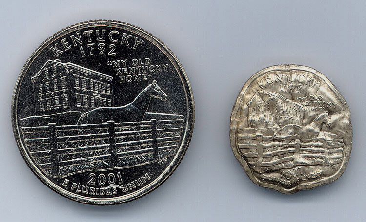
In quarter-shrinking, I always found that the outer perimeter of the coin was the most distorted--usually with a ripple'ed edges. Does anyone know how, or if, the 'frequency' of those ripples have anything to do with the LC resonant frequency? NOW, would the quality of the shrunken coin be improved if, during the shrinking process, the coin is confined to that uniform central region? Of course this would require the coin to be centered in a larger diameter coil, and probably also need a significantly more energetic capacitor charge since a fraction of the field (the extremely non-uniform outer portion) is not utilized.
Briefly, here is how I see the general coin-shrinking process (please correct me or add/subtract information as needed): The coil's counter mmf results in a huge coin current of about 10 times that in a 10-turn coil due to 'transformer action' + the coin acting as a single shorted turn. The direction of this induced coin current obeys Lenz's law and flows as circular eddy currents in such a direction as to interact with the induced B-field producing a Lorentz force directed radically to the coin's center thus shrinking it.
Re: COIN SHRINKING: in a B-field of improved uniformity
Andy, Fri Feb 27 2015, 06:40AM
I would say that the two fields are oppsite, but that the coin can produce larger current to equal the primary, amp.turns, but the strength ist related to turns more j,E,B, so it can compress more than the primary.
It should show closest to the wire as at that point is the closest field reverasble., oppsite equal,oppsite.
Re: COIN SHRINKING: in a B-field of improved uniformity
DerAlbi, Fri Feb 27 2015, 02:41PM
If you see ripples in the metal imho the current is to low and pulse is too long.
Here is why i think this: While the coil inside shrinks the coil outside expands.
I am just guessing here, but since those guys here

have no ripples (correct me, but i dont know what to look for - i just find them good enough).. i think we need to think for the difference to other guys.
The link presents a vaporizing coil. It has a very high expansion force.
What i think can go wrong - specially then the pulse is too long - that the outside coil doesnt perfecly expand but due to springaction it kind of oscillates during expansion with one of its mechanical eigenfrequencies.
The faster the outside coil expands (explodes) the needed eigenfrequency gets higher and higher until its just smoth.
Maybe if you could give an example what effect you want to avoid (pics!) the would be a more solid discussion.
DerAlbi, Fri Feb 27 2015, 02:41PM
If you see ripples in the metal imho the current is to low and pulse is too long.
Here is why i think this: While the coil inside shrinks the coil outside expands.
I am just guessing here, but since those guys here
have no ripples (correct me, but i dont know what to look for - i just find them good enough).. i think we need to think for the difference to other guys.
The link presents a vaporizing coil. It has a very high expansion force.
What i think can go wrong - specially then the pulse is too long - that the outside coil doesnt perfecly expand but due to springaction it kind of oscillates during expansion with one of its mechanical eigenfrequencies.
The faster the outside coil expands (explodes) the needed eigenfrequency gets higher and higher until its just smoth.
Maybe if you could give an example what effect you want to avoid (pics!) the would be a more solid discussion.
Re: COIN SHRINKING: in a B-field of improved uniformity
Signification, Sat Feb 28 2015, 08:59PM
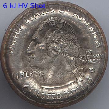
DerAlbi: In the video, I think these guys are using WAY to much capacitance and energy! The ripples I spoke of are along the thickness of the edge of the coin, not over the surface. If you inked the edge of the quarter and rolled it down the floor, it would draw a sine wave! At the outer perimeter, the coin is not flat for only about 10% along a diameter.
--------------
Andy: Yes, I think your last statement may explain the strange perimeter pattern, though I am still wondering if this sinesoidal deformation is related to the LC constant.
---------------
The following is from several years ago...At first I only had ten 32uF 4.5kJ, I don't even remember if I ever used all ten. The result was a quarter that you had to compare with another one to see it was actually smaller (in dia.). Then I got my first giant energy capacitors! Two orange Maxwell energy caps each rated at 12kV @ 70uF. I used them in parallel and charged them with a rectified NST. each coin was centered in ten turns of 10AWG magnet wire. First shot: @ 5kV (1750J) gave -noticeable- results. Then after a 10kV shot, it took a while to find the quarter (in a giant holography sandbox) and there was a LOT of 'thinned' razer sharp exploded shrapnel (NEVER do this unless the coil is covered and in something virtually bullet-proof!). When I finally found it--I was shocked--looking at that TINY little quarter (it was heads). It was too hot to pick up.
So I found it took a variable (use a variac to the NST) energy cap bank (140uF in my case) of a minimum of, say, 2kJ to a maximum of 6kJ to 7kJ to control the quarter diameter from just un-noticable to -much- smaller than a dime (7kJ). I could control the voltage to get diameters precisely equal to a nickel, a penny, and a dime. And much smaller, although past this they start getting very thick--to the point they look fake. Note that this is all with the same ten-turn 10AWG wire and 140uF capacitance. I intend to broaden these two parameters. A good project would be to find the least-energy capacitor bank to shrink to the smallest desired diameter.
A RE-USABLE COIL:
I found (to my surprise) that if I coated the coil in fiber (cloth) resin it became much more resilient to the current pulse! I got a few shots at medium energy until it was un-usable. The coil did not explode, but the coin AND wire shrunk! I remember then cranking the energy up and the coil exploded while the coin shrunk less, of course, than normal for this energy level. Then I made big (really big) blocks of cloth fiber, but have not tried them YET! I encased wire of 10AWG, 3-layer 10AWG, ribbon magnet ~1/4" wide x 1/16" thick, and a monster coil of ten turns of huge square (1/4" x 1/4") magnet wire which took a special tool to wind. I will post some photos of this stuff soon (people got all my quarters though, I did manage to hold onto my last one until I traded it for a laser ruby!--I will make more). I will include a photo showing the rig with which I plan to shrink coins in the uniform field, but I am afraid that these big potted 'shrinkers' may not protect the -inside- of the coil in the blast BUT my new method very well could, as the coil will be protected inside also.
A REALLY strange effect: After looking at the dime-sized quarter a while, a regular quarter appears "freakishly" expanded.
Signification, Sat Feb 28 2015, 08:59PM
DerAlbi: In the video, I think these guys are using WAY to much capacitance and energy! The ripples I spoke of are along the thickness of the edge of the coin, not over the surface. If you inked the edge of the quarter and rolled it down the floor, it would draw a sine wave! At the outer perimeter, the coin is not flat for only about 10% along a diameter.
--------------
Andy: Yes, I think your last statement may explain the strange perimeter pattern, though I am still wondering if this sinesoidal deformation is related to the LC constant.
---------------
The following is from several years ago...At first I only had ten 32uF 4.5kJ, I don't even remember if I ever used all ten. The result was a quarter that you had to compare with another one to see it was actually smaller (in dia.). Then I got my first giant energy capacitors! Two orange Maxwell energy caps each rated at 12kV @ 70uF. I used them in parallel and charged them with a rectified NST. each coin was centered in ten turns of 10AWG magnet wire. First shot: @ 5kV (1750J) gave -noticeable- results. Then after a 10kV shot, it took a while to find the quarter (in a giant holography sandbox) and there was a LOT of 'thinned' razer sharp exploded shrapnel (NEVER do this unless the coil is covered and in something virtually bullet-proof!). When I finally found it--I was shocked--looking at that TINY little quarter (it was heads). It was too hot to pick up.
So I found it took a variable (use a variac to the NST) energy cap bank (140uF in my case) of a minimum of, say, 2kJ to a maximum of 6kJ to 7kJ to control the quarter diameter from just un-noticable to -much- smaller than a dime (7kJ). I could control the voltage to get diameters precisely equal to a nickel, a penny, and a dime. And much smaller, although past this they start getting very thick--to the point they look fake. Note that this is all with the same ten-turn 10AWG wire and 140uF capacitance. I intend to broaden these two parameters. A good project would be to find the least-energy capacitor bank to shrink to the smallest desired diameter.
A RE-USABLE COIL:
I found (to my surprise) that if I coated the coil in fiber (cloth) resin it became much more resilient to the current pulse! I got a few shots at medium energy until it was un-usable. The coil did not explode, but the coin AND wire shrunk! I remember then cranking the energy up and the coil exploded while the coin shrunk less, of course, than normal for this energy level. Then I made big (really big) blocks of cloth fiber, but have not tried them YET! I encased wire of 10AWG, 3-layer 10AWG, ribbon magnet ~1/4" wide x 1/16" thick, and a monster coil of ten turns of huge square (1/4" x 1/4") magnet wire which took a special tool to wind. I will post some photos of this stuff soon (people got all my quarters though, I did manage to hold onto my last one until I traded it for a laser ruby!--I will make more). I will include a photo showing the rig with which I plan to shrink coins in the uniform field, but I am afraid that these big potted 'shrinkers' may not protect the -inside- of the coil in the blast BUT my new method very well could, as the coil will be protected inside also.
A REALLY strange effect: After looking at the dime-sized quarter a while, a regular quarter appears "freakishly" expanded.
Re: COIN SHRINKING: in a B-field of improved uniformity
Uspring, Wed Mar 04 2015, 11:24AM
Uspring, Wed Mar 04 2015, 11:24AM
The central region of a cross-sectional area showed mostly blue and cyan (about 80%) while the green, yellow, reddish, hugged the inner wall.For long and thin tightly wound solenoids the field is nearly homogeneous inside the coil. For shorter thicker ones, the filed is somewhat weaker in the center. If the coil is not tightly wound, i.e. you have some room between the windings, the field is a bit stronger near the winding and weaker inbetween. This does not depend on current strength. A larger current will just multiply the field by a constant factor.
Does anyone know how, or if, the 'frequency' of those ripples have anything to do with the LC resonant frequency?Possibly this has to do with the fact, that the field is not homogeneous near the windings. Or the coin might just buckle in some way.
Note that this is all with the same ten-turn 10AWG wire and 140uF capacitance. I intend to broaden these two parameters. A good project would be to find the least-energy capacitor bank to shrink to the smallest desired diameter.There is an optimal time constant (i.e. 1/sqrt(L*C)) for shrinking. The current induced in the coin will increase for shorter pulses, since the voltage induced in the coin is proportional to the rate of change of the magnetic field. At a certain point, though, the induced current will produce a strong field opposite to that of the coil. That will limit the coin current. Going beyond that point will only increase losses due to ESR and coil resistance. That has been discussed e.g. here:
Re: COIN SHRINKING: in a B-field of improved uniformity
klugesmith, Thu Mar 05 2015, 07:40PM
Let me begin with a respectful bow toward someone who has actually made and used a quarter shrinker. My 52 uF 20 kV (10.4 kJ) Aerovox capacitor was purchased with that in mind, but I stopped after cutting cans in half with 1 kJ. Too many projects, too little time. And I don't want to risk damage to the capacitor, lately serving as a door stop.
Using "transformer action" formula to predict current in the shorted turn is wrong in my opinion. It works in ordinary transformer applications, where the secondary ampere-turns practically cancel the primary ampere-turns. A small remainder of ampere-turns cyclically magnetizes the core, enough that the induced "back EMF" matches the applied volts per turn.
I think a better model starts with the secondary volts per turn (similar to primary volts per turn) divided by the resistance of the shorted turn. In the Al-can case, that's substantially less than N times the primary current. The resulting current does reduce the B-field that would be there if no workpiece were present, and reduces the inductance seen by power source. Has anyone here seen a quantitative model published, even in the simplified case where workpiece and coil don't move?
The system ought to be linear for all energy levels too low for metal to move during the shot. (Except the coil and workpiece resistivity increase progressively during the shot because of Joule heating.) In a quarter-shrinker fired with insufficient energy to move things, before-and-after temperature measurements could show how 100% of original capacitor energy is partitioned between coil heating and workpiece heating.
klugesmith, Thu Mar 05 2015, 07:40PM
Signification wrote ...
Briefly, here is how I see the general coin-shrinking process (please correct me or add/subtract information as needed): The coil's counter mmf results in a huge coin current of about 10 times that in a 10-turn coil due to 'transformer action' + the coin acting as a single shorted turn. The direction of this induced coin current obeys Lenz's law and flows as circular eddy currents in such a direction as to interact with the induced B-field producing a Lorentz force directed radically to the coin's center thus shrinking it.
Briefly, here is how I see the general coin-shrinking process (please correct me or add/subtract information as needed): The coil's counter mmf results in a huge coin current of about 10 times that in a 10-turn coil due to 'transformer action' + the coin acting as a single shorted turn. The direction of this induced coin current obeys Lenz's law and flows as circular eddy currents in such a direction as to interact with the induced B-field producing a Lorentz force directed radically to the coin's center thus shrinking it.
Let me begin with a respectful bow toward someone who has actually made and used a quarter shrinker. My 52 uF 20 kV (10.4 kJ) Aerovox capacitor was purchased with that in mind, but I stopped after cutting cans in half with 1 kJ. Too many projects, too little time. And I don't want to risk damage to the capacitor, lately serving as a door stop.
Using "transformer action" formula to predict current in the shorted turn is wrong in my opinion. It works in ordinary transformer applications, where the secondary ampere-turns practically cancel the primary ampere-turns. A small remainder of ampere-turns cyclically magnetizes the core, enough that the induced "back EMF" matches the applied volts per turn.
I think a better model starts with the secondary volts per turn (similar to primary volts per turn) divided by the resistance of the shorted turn. In the Al-can case, that's substantially less than N times the primary current. The resulting current does reduce the B-field that would be there if no workpiece were present, and reduces the inductance seen by power source. Has anyone here seen a quantitative model published, even in the simplified case where workpiece and coil don't move?
The system ought to be linear for all energy levels too low for metal to move during the shot. (Except the coil and workpiece resistivity increase progressively during the shot because of Joule heating.) In a quarter-shrinker fired with insufficient energy to move things, before-and-after temperature measurements could show how 100% of original capacitor energy is partitioned between coil heating and workpiece heating.
Re: COIN SHRINKING: in a B-field of improved uniformity
hen918, Thu Mar 05 2015, 09:09PM
Even when it does move things, the energy should still end up as heat
hen918, Thu Mar 05 2015, 09:09PM
klugesmith wrote ...
Let me begin with a respectful bow toward someone who has actually made and used a quarter shrinker. My 52 uF 20 kV (10.4 kJ) Aerovox capacitor was purchased with that in mind, but I stopped after cutting cans in half with 1 kJ. Too many projects, too little time. And I don't want to risk damage to the capacitor, lately serving as a door stop.
Using "transformer action" formula to predict current in the shorted turn is wrong in my opinion. It works in ordinary transformer applications, where the secondary ampere-turns practically cancel the primary ampere-turns. A small remainder of ampere-turns cyclically magnetizes the core, enough that the induced "back EMF" matches the applied volts per turn.
I think a better model starts with the secondary volts per turn (similar to primary volts per turn) divided by the resistance of the shorted turn. In the Al-can case, that's substantially less than N times the primary current. The resulting current does reduce the B-field that would be there if no workpiece were present, and reduces the inductance seen by power source. Has anyone here seen a quantitative model published, even in the simplified case where workpiece and coil don't move?
The system ought to be linear for all energy levels too low for metal to move during the shot. (Except the coil and workpiece resistivity increase progressively during the shot because of Joule heating.) In a quarter-shrinker fired with insufficient energy to move things, before-and-after temperature measurements could show how 100% of original capacitor energy is partitioned between coil heating and workpiece heating.
Signification wrote ...
Briefly, here is how I see the general coin-shrinking process (please correct me or add/subtract information as needed): The coil's counter mmf results in a huge coin current of about 10 times that in a 10-turn coil due to 'transformer action' + the coin acting as a single shorted turn. The direction of this induced coin current obeys Lenz's law and flows as circular eddy currents in such a direction as to interact with the induced B-field producing a Lorentz force directed radically to the coin's center thus shrinking it.
Briefly, here is how I see the general coin-shrinking process (please correct me or add/subtract information as needed): The coil's counter mmf results in a huge coin current of about 10 times that in a 10-turn coil due to 'transformer action' + the coin acting as a single shorted turn. The direction of this induced coin current obeys Lenz's law and flows as circular eddy currents in such a direction as to interact with the induced B-field producing a Lorentz force directed radically to the coin's center thus shrinking it.
Let me begin with a respectful bow toward someone who has actually made and used a quarter shrinker. My 52 uF 20 kV (10.4 kJ) Aerovox capacitor was purchased with that in mind, but I stopped after cutting cans in half with 1 kJ. Too many projects, too little time. And I don't want to risk damage to the capacitor, lately serving as a door stop.
Using "transformer action" formula to predict current in the shorted turn is wrong in my opinion. It works in ordinary transformer applications, where the secondary ampere-turns practically cancel the primary ampere-turns. A small remainder of ampere-turns cyclically magnetizes the core, enough that the induced "back EMF" matches the applied volts per turn.
I think a better model starts with the secondary volts per turn (similar to primary volts per turn) divided by the resistance of the shorted turn. In the Al-can case, that's substantially less than N times the primary current. The resulting current does reduce the B-field that would be there if no workpiece were present, and reduces the inductance seen by power source. Has anyone here seen a quantitative model published, even in the simplified case where workpiece and coil don't move?
The system ought to be linear for all energy levels too low for metal to move during the shot. (Except the coil and workpiece resistivity increase progressively during the shot because of Joule heating.) In a quarter-shrinker fired with insufficient energy to move things, before-and-after temperature measurements could show how 100% of original capacitor energy is partitioned between coil heating and workpiece heating.
Even when it does move things, the energy should still end up as heat
Re: COIN SHRINKING: in a B-field of improved uniformity
Uspring, Fri Mar 06 2015, 09:36AM
Uspring, Fri Mar 06 2015, 09:36AM
Has anyone here seen a quantitative model published, even in the simplified case where workpiece and coil don't move?IMHO a transformer model with a coupling lower than one might work. A k<1 will account for not all of the primary field going through the secondary and vice versa.
Re: COIN SHRINKING: in a B-field of improved uniformity
klugesmith, Fri Mar 06 2015, 08:24PM
The available energy is not enough to vaporize (or even melt) more than a tiny fraction of the copper mass.
Aside from heating, the workpiece and coil consume energy in plastic deformation, being torn to bits, and being launched at high velocity. The last part soon converts to air motion, damage to the fragment shield, and heat.
Sig's report of re-using shrinker coils was enlightening. My thoughts in that department had drifted toward a flexible shaft coupling geometry.

klugesmith, Fri Mar 06 2015, 08:24PM
DerAlbi wrote ...
... those guys here have no ripples ...
The link presents a vaporizing coil. It has a very high expansion force.
It always bugged me that the Hackerbot video caption says their coil vaporized.... those guys here
have no ripples ...The link presents a vaporizing coil. It has a very high expansion force.
The available energy is not enough to vaporize (or even melt) more than a tiny fraction of the copper mass.
Aside from heating, the workpiece and coil consume energy in plastic deformation, being torn to bits, and being launched at high velocity. The last part soon converts to air motion, damage to the fragment shield, and heat.
Sig's report of re-using shrinker coils was enlightening. My thoughts in that department had drifted toward a flexible shaft coupling geometry.

Re: COIN SHRINKING: in a B-field of improved uniformity
Signification, Sat Mar 07 2015, 10:11PM
I remember once when Washington's right profile was deeply imprinted in a piece of the rosin--I must have had the quarter un-centered in that direction. I just checked the coupler on my homemade ciolwinder--A great match!
Signification, Sat Mar 07 2015, 10:11PM
I remember once when Washington's right profile was deeply imprinted in a piece of the rosin--I must have had the quarter un-centered in that direction. I just checked the coupler on my homemade ciolwinder--A great match!
Re: COIN SHRINKING: in a B-field of improved uniformity
Bert, Mon Mar 23 2015, 02:37AM
Interesting work, Sig! I mostly agree with your conclusions.
It looks like we have similar Maxwell capacitors - mine are Maxwell model 33252, 70 uF at 12 kV, arranged in a bank of two or three caps in parallel. I've found them to be very reliable. Maxwell spec's them for a lifetime of 100,000 shots at 100 kA/shot, and after shrinking well over 6,000 coins, the only failure I encountered was during a cold snap in the winter of 2014. The Quarter Shrinker is housed in an unheated enclosed porch. Unbeknownst to me, the castor oil dielectric fluid "froze" during an extended cold wave. I now know (with 20-20 hindsight and a discussion with GA's capacitor engineers) that when castor oil freezes at around 14F (-10C), small amounts of dissolved water come out of solution and are absorbed by the kraft paper dielectric. This significantly reduces its dielectric strength. During charging, one cap in the pair abruptly faulted at about 8500 volts, dumping about 5 kJ of energy into the short-circuited cap. Fortunately, the welded metal case held, preventing any fluid leakage, but the capacitor was destroyed, The remaining caps now have strip heaters to keep them toasty all winter long.
I'll be very interested in your progress towards more permanent work coils, When I first started shrinking coins, I also looked at various techniques to keep the work coil together including experimenting with fiberglass and resin. However, the heaviest radial forces seem to be confined to the 1 or 2 turns that are directly over the coin. I was unable to find any approach that would keep this portion of the coil from self-destructing at anywhere near normal shrinking energies. I think it may be an energy density thing associated with coin shrinking, since epoxy-reinforced work coils DO work quite well for commercial electromagnetic metal forming. These EM forming systems seem to spread out repulsion forces more evenly across the work coil or they use field shaping techniques. For example, I looked at using a heavy slotted cylindrical conductor (a "flux concentrator") between the work coil and coin to more evenly distribute forces across the entire length of the work coil. While this might prolong the work coil's life, I concluded that the presence of the gap in the concentrator would cause an unacceptable "kink" in the coin at the gap. And, that double-build 200C magnet wire was easy to use for multiple coin diameters and, even if sacrificial, was still very cost-effective.
I agree that coin wrinkling may be mechanical buckling. Once it begins, further shrinking may intensify the effect. And, some coins, such as US small (golden) dollars, seldom show any wrinkling even though magnetic forces are similar. I found that wrinkling can be prevented, or at least minimized, by using the appropriate dowel material to hold the coin firmly in position perpendicular to the coil H-field while also constraining the perimeter of the coin during the initial stages of shrinking. Choosing the right material is important. I initially used wooden dowels, but these quickly shattered and often left an imprint of the wood grain on the coin's faces. I also tried a variety of polymer rods. Denser or harder polymers caused the surface features of the coins to become unattractively flattened. After much experimentation, I got the best results with natural UHMW rod for US clad coins, and nylon for some silver alloy coins. Curiously, clad coins sometimes contain hidden cladding defects between the outer Ci-Ni layers and the inner Cu substrate. During shrinking, the improperly bonded regions cause interesting force imbalances and "Mutant coins"
Raising the natural frequency of the LC circuit does have some interesting effects on the final shape of coins even when using identical energy levels. A lower bank capacitance and higher voltage results in the outer edge of the coin becoming significantly thicker along the perimeter than in the center - a property likened to "toroiding". Using a higher bank capacitance reduces, but does not eliminate this effect, particularly for large coins. Using even higher bank capacitance seems to reduce shrinking efficiency - probably because of reduced di/dt. The "sweet spot" for single-layer coils seems to be with "square" shaped ~10-turn coils with diameter approximately equal to length. We use #10 through #14 AWG round 200C double-build magnet wire to cover various coin sizes from dimes through Silver Eagles (0.7 - 1.6"). Work coil current measurements with a Pearson CT shows that work coils seem to stay intact during most/all of the first current half-cycle, even though the shape of the coil may change dramatically prior to self-destructing. There is some evidence that the inertial of the work coil helps "keep things together" during the critical 1/4 cycle to the first primary current peak, and it's not especially critical that the coil stay intact after this point.
Re: COIN SHRINKING: in a B-field of improved uniformity
Signification, Wed Apr 01 2015, 07:16PM
Bert,
6000 coins...WOW!!! I'm at about 30 (..don't have a convenient setup yet) ...don't relax during the procedure, no matter how many--it just takes one tiny slip... Also you seem to be on track to advancement in the art. What is your trigger method?
It does seem like our setups will be similar in time and space! Yes, I looked at the Maxwell capacitors that I have (2) and they are the same model--are yours orange? I an a bit concerned...It has been several years since I used them and they were outside (unenclosed back porch) in some rather hard freezes!! Do you have a source for these? I have just received the following from McMaster Carr: (all 1-1/4" dia x 2' long for ~1" quarters). I ordered then after reading your message:
1) Easy-to-Machine ABS Rod
2) Self-Lubricating MDS-filled Nylon Rod (Black)
3) Self-Lubricating Oil-Filled UHMW Polyethylene rod
all to be cut for end pieces.
I have not found a great formula yet for reusable windings (haven't really tried so far either) but hope to have the time soon. As I mentioned, I will try keeping the coin in a constant B-strength region, which require a first try of centering the the coin in the ends of the 1-1/4" rods. I plan to drill a 'coin sink' pit with a depth of 1/2 the coin thickness on each rod end. I tested this by using a 1" wood bit (with those nasty teeth at the outer edged filed away). I found this difficult to center. Then I discovered that on the inside of plastic caps (for spray paint etc.) the center has a small cup that is -exactly- 1-1/4" ID and usually a dimple dead center in which to punch a hole, after it is slid over the rod--it's a perfect fit! I also have 8, 9, 10, 12 gauge wire and 6 and 8 gauge insulated wire. I previously used 9 turns of 10AWG magnet.
I want to try insulated wire buried in fiberglass-cloth resin. Since I am not placing the coin edge at the outer ID of the coil, there will be a 1/8" gap all around the 1-1/4" ID which I plan to have filled with the potting. I realize this may require more cap energy (maybe close to the one klugesmith mentioned for coin-shrinking use-I don't recall the specs, but they caught my attention), but if it works--so what, right? Is efficiency that important here if you get a reusable coil that puts out excellent coins? One sort of wild thought was to form a Brooks config with a 3x3 coil. Here, I am worried about divergent B-Fields, but have learned, especially with shrinking, the unexpected seems to work more often than not. I want to work on tuning, decaying oscillations, critical damping...
I have found that PAM non-stick (for cooking) to be invaluable in removing the cured cloth resin.
I do have some samples of potted coils that I want to post photos of. I can't believe I let people take my last coin!!!!!!!!!!!
...more when I get started again...
Re: COIN SHRINKING: in a B-field of improved uniformity
Bert, Tue Apr 07 2015, 08:34PM
We used to use a trigatron for many years but it sometimes unexpectedly self-discharged (surprise - BANG!!). I HATE 6 kJ surprises. Sometimes it failed to fire (particularly at lower voltage levels). And, it required excessive maintenance. After many years we converted to a a solenoid-driven switch (see below). This has been relatively trouble-free ever since and reliably works over a wide range of voltages. The only problem is that some of the zinc in (from the brass electrodes) is vaporized, and deposited as zinc oxide on the inner surfaces of the Lexan housing. I would strongly recommend using some type of housing around the gap to reduce the noise level when the switch fires.
No such luck. I got mine off eBay over 15 years ago, and mine are also orange. Had to drive to central Ohio to pick them up. Simply storing them in a cold place should be OK as long as they have thoroughly warmed up before applying voltage to them. Maxwell specs their storage temperature range as -20C - 60C (-4F - 140F). However, the Maxwell engineer I talked with said that these caps could be stored at even colder temperatures as long as they had fully stabilized to a temperature above -10C (14F) before voltage was applied.
Increasing the space between inside of the coil and coin reduces coupling and seems to decrease shrinkage "efficiency". I've always try to minimize this space but not so much that flashovers occur between the coin and coil.
Many years ago, an experimenter in the Pacific Northwest told me that he was efficiently shrinking coins using a multilayer coil wound with something like 16 - 18 turns of vinyl-insulated hookup wire, so your proposed technique might work as long as you can prevent the coin from twisting relative to the now shorter coil. He was using relatively small Sprague 14uF 20kV energy discharge caps off the surplus market.

Bert, Tue Apr 07 2015, 08:34PM
Signification wrote ...
Bert,
6000 coins...WOW!!! I'm at about 30 (..don't have a convenient setup yet) ...don't relax during the procedure, no matter how many--it just takes one tiny slip... Also you seem to be on track to advancement in the art. What is your trigger method?
Bert,
6000 coins...WOW!!! I'm at about 30 (..don't have a convenient setup yet) ...don't relax during the procedure, no matter how many--it just takes one tiny slip... Also you seem to be on track to advancement in the art. What is your trigger method?
We used to use a trigatron for many years but it sometimes unexpectedly self-discharged (surprise - BANG!!). I HATE 6 kJ surprises. Sometimes it failed to fire (particularly at lower voltage levels). And, it required excessive maintenance. After many years we converted to a a solenoid-driven switch (see below). This has been relatively trouble-free ever since and reliably works over a wide range of voltages. The only problem is that some of the zinc in (from the brass electrodes) is vaporized, and deposited as zinc oxide on the inner surfaces of the Lexan housing. I would strongly recommend using some type of housing around the gap to reduce the noise level when the switch fires.
Signification wrote ...
It does seem like our setups will be similar in time and space! Yes, I looked at the Maxwell capacitors that I have (2) and they are the same model--are yours orange? I an a bit concerned...It has been several years since I used them and they were outside (unenclosed back porch) in some rather hard freezes!! Do you have a source for these?
It does seem like our setups will be similar in time and space! Yes, I looked at the Maxwell capacitors that I have (2) and they are the same model--are yours orange? I an a bit concerned...It has been several years since I used them and they were outside (unenclosed back porch) in some rather hard freezes!! Do you have a source for these?
No such luck. I got mine off eBay over 15 years ago, and mine are also orange. Had to drive to central Ohio to pick them up. Simply storing them in a cold place should be OK as long as they have thoroughly warmed up before applying voltage to them. Maxwell specs their storage temperature range as -20C - 60C (-4F - 140F). However, the Maxwell engineer I talked with said that these caps could be stored at even colder temperatures as long as they had fully stabilized to a temperature above -10C (14F) before voltage was applied.
Signification wrote ...
I want to try insulated wire buried in fiberglass-cloth resin. Since I am not placing the coin edge at the outer ID of the coil, there will be a 1/8" gap all around the 1-1/4" ID which I plan to have filled with the potting. I realize this may require more cap energy (maybe close to the one klugesmith mentioned for coin-shrinking use-I don't recall the specs, but they caught my attention), but if it works--so what, right? Is efficiency that important here if you get a reusable coil that puts out excellent coins?
I want to try insulated wire buried in fiberglass-cloth resin. Since I am not placing the coin edge at the outer ID of the coil, there will be a 1/8" gap all around the 1-1/4" ID which I plan to have filled with the potting. I realize this may require more cap energy (maybe close to the one klugesmith mentioned for coin-shrinking use-I don't recall the specs, but they caught my attention), but if it works--so what, right? Is efficiency that important here if you get a reusable coil that puts out excellent coins?
Increasing the space between inside of the coil and coin reduces coupling and seems to decrease shrinkage "efficiency". I've always try to minimize this space but not so much that flashovers occur between the coin and coil.
Signification wrote ...
One sort of wild thought was to form a Brooks config with a 3x3 coil. Here, I am worried about divergent B-Fields, but have learned, especially with shrinking, the unexpected seems to work more often than not. I want to work on tuning, decaying oscillations, critical damping...
I have found that PAM non-stick (for cooking) to be invaluable in removing the cured cloth resin.
Many years ago, an experimenter in the Pacific Northwest told me that he was efficiently shrinking coins using a multilayer coil wound with something like 16 - 18 turns of vinyl-insulated hookup wire, so your proposed technique might work as long as you can prevent the coin from twisting relative to the now shorter coil. He was using relatively small Sprague 14uF 20kV energy discharge caps off the surplus market.

Print this page