
Induction heated nightmare
Davebmx, Wed Jan 14 2015, 06:20PMHi everyone hope your all having a nice new year!
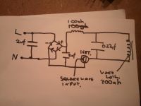
I'm hoping that someone may be able to assist me on a project im currently working on which is a mains powered induction heater.
im using a quasi resonant arangement using a single fga25n120 igbt triggered by an adjsutable square wave generator coded onto an 8 bit chip. Its basically a clone of a very cheap style of induction hob.
my oscillator is run from a seperate 15v supply and the heater will succesfully heat object in the work coil if i bypass the rectifier and use a 16v bench top power supply.
However when i switch to a 10a variac connected to the rectifier i see a huge magnetic field in the coil which just moves the work piece but doesnt heat it and i see whopping current drain even at low voltages.
Now i'm pretty sure its something small i am overlooking as its a simple circuit! please note im running all my mains tests through an isolation transformer so i can scope it.
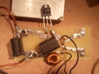
Ive included a quick sketch of my circuit and also a photo of the quick testing pcb i made up please dont bash the design i made it in 20 mins :]
please note the igbt has been desoldered to test if its died or not but is right over where it solders on to the board
i'd be very grateful for any help as its not something im too familiar with and its quite frustrating not not knowing why i cant get it to work
regards
also i just noticed my 5uf cap is wrong on the diagram, it goes from the negative location to after the choke on the positive rail not before! ooops
Dave
Re: Induction heated nightmare
..., Wed Jan 14 2015, 06:45PM
As drawn your bridge rectifier will not work, which would explain your issues. Be safe.
..., Wed Jan 14 2015, 06:45PM
As drawn your bridge rectifier will not work, which would explain your issues. Be safe.
Re: Induction heated nightmare
Davebmx, Wed Jan 14 2015, 07:09PM
Thanks for the reply! i just scribbled the rectifier but it is correct on the pcb!
regards
Dave
Davebmx, Wed Jan 14 2015, 07:09PM
Thanks for the reply! i just scribbled the rectifier but it is correct on the pcb!
regards
Dave
Re: Induction heated nightmare
Kolas, Wed Jan 14 2015, 09:38PM
well, either your IGBT/mosfet is a short, or your rectifier is backwards (which might have produced a dead switch also)
there's many ways to test the switch, and its fairly easy to check your rectifier.
Kolas, Wed Jan 14 2015, 09:38PM
well, either your IGBT/mosfet is a short, or your rectifier is backwards (which might have produced a dead switch also)
there's many ways to test the switch, and its fairly easy to check your rectifier.
Re: Induction heated nightmare
Davebmx, Thu Jan 15 2015, 10:06AM
Thanks Kolas, the rectifier works as it should i have just drawn it wrong. i have also tested it with a different rectifier and a bunch of caps in parallel equaling about 20 000 uf as i had thought it might be ripple that was killing the igbt even though this circuit should be able to handle unsmoothed rectified dc. i wonder now if im getting some sort of ringing that is causing the igbt to switch out of zvs. i have noticed a change in the square wave output of the oscillator when the circuit is connected to a power supply that looks very saw tooth with distinct Sinusoidal properties! i will try get some snaps of the scope tonight
regards
Dave
Re: Induction heated nightmare
Dr. Dark Current, Thu Jan 15 2015, 02:31PM
Hello,
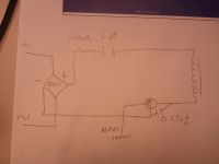
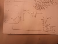
the 100uH inductor is placed wrong, I think it's usually used only as a noise suppresion inductor before the 5uF cap. The work coil would then go from the positive end of the 5uF filter cap to the IGBT collector, and the 0.27uF cap would go in parallel to the igbt (between the collector and emitter).
Re: Induction heated nightmare
Davebmx, Thu Jan 15 2015, 03:10PM
Hi Dr Dark Current and thanks for your reply!
Ive done a quick redraw following what you have said. Would this alter the circuit from a parallel resonant circuit to a series resonant?
anyway heres the drawing is this what you meant?
regards Dave
Davebmx, Thu Jan 15 2015, 03:10PM
Hi Dr Dark Current and thanks for your reply!
Ive done a quick redraw following what you have said. Would this alter the circuit from a parallel resonant circuit to a series resonant?
anyway heres the drawing is this what you meant?
regards Dave

Re: Induction heated nightmare
Davebmx, Thu Jan 15 2015, 03:37PM
sorry did you mean like this?
regards
Dave
Davebmx, Thu Jan 15 2015, 03:37PM
sorry did you mean like this?
regards
Dave

Re: Induction heated nightmare
Kolas, Thu Jan 15 2015, 08:15PM
I'm pretty sure that this circuit was closer to correct before, having the little cap be PFC for the work coil making a parallel resonant circuit. But something to realize here is that in order to achieve ZCS you need to be switching based on the tank's current via feed back. A simple 555 circuit is unlikely to be "tuned" correctly. Any work pieces inside the coil will cause the effective inductance of your work coil will change, and therefore the resonant frequency has changed.
I also believe that the 100uh inductor is meant to add impedance to the tank and acts as a fail safe (it needs to be a matched inductor to your PFC)
i recommend you read this page.

Re: Induction heated nightmare
Davebmx, Fri Jan 16 2015, 10:15AM
Hi Kolas!
been through Mr Burnetts page many times haha! he does say that aslong as the frequency is on the high side of resonance it should only cause loss of power or for the whole thing to drop out of resonance but i am having catastrophic failure of the igbt? the heater will also be used to heat the same load everytime so once i find the resonance i can just leave it calibrated. under 16v dc from my bench supply the heater draws 4 amps and gently heats the load in the coil. when i hook it up to a 10a variac running through a rectifier and 20 000uf of smoothing at about 15 volts it appears to be trying to draw 40amps! im assuming for some reason or another the igbt is latching open causing the work coil to act as a huge heating element, resulting in the huge current drain.
regards
Dave
Re: Induction heated nightmare
Wolfram, Fri Jan 16 2015, 02:13PM
This is not right, see the attached schematic, taken from . The rectifier is drawn wrong in the application note, but otherwise it's correct
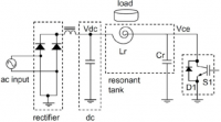
That's true for the LCLR or series resonant induction heaters driven from a half- or fullbridge, but not for this quasi-resonant circuit we're discussing here. For the quasi-resonant circuit, it is generally very important to have¨close to zero voltage switching at all times. The application note I linked shows some example waveforms. This type of induction heater is generally very easy to kill when operating open-loop from an oscillator.
Wolfram, Fri Jan 16 2015, 02:13PM
This is not right, see the attached schematic, taken from
 . The rectifier is drawn wrong in the application note, but otherwise it's correct
Davebmx wrote ...
Hi Kolas!
been through Mr Burnetts page many times haha! he does say that aslong as the frequency is on the high side of resonance it should only cause loss of power or for the whole thing to drop out of resonance but i am having catastrophic failure of the igbt?
Hi Kolas!
been through Mr Burnetts page many times haha! he does say that aslong as the frequency is on the high side of resonance it should only cause loss of power or for the whole thing to drop out of resonance but i am having catastrophic failure of the igbt?
That's true for the LCLR or series resonant induction heaters driven from a half- or fullbridge, but not for this quasi-resonant circuit we're discussing here. For the quasi-resonant circuit, it is generally very important to have¨close to zero voltage switching at all times. The application note I linked shows some example waveforms. This type of induction heater is generally very easy to kill when operating open-loop from an oscillator.
Re: Induction heated nightmare
Davebmx, Sun Jan 25 2015, 04:53PM
thankyou Wolfram that is an excellent source¬
so, if i stick to my initial circuit sans the dodgy rectifier drawing i am in the right direction? I have the oscillator coded to an 8 bit chip as i have always planned to integrate feedback resonant control later on. To add this function however i would need to know what i should be measuring and also where to measure it from. I'm assuming i would need to measure it directly from the work coil through a large value resistor but how do i find the resonant frequency if i cant get the circuit to run without the feedback initially to get my baseline figures?
kind regards
Dave
Re: Induction heated nightmare
Linas, Sun Jan 25 2015, 07:24PM
I like this circuit, it should heat up quite fast :D
(complete short circuit)
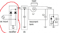
Linas, Sun Jan 25 2015, 07:24PM
I like this circuit, it should heat up quite fast :D
(complete short circuit)

Re: Induction heated nightmare
hen918, Sun Jan 25 2015, 10:09PM
Yeah, I noticed that, I almost commented at the time.
You would have thought Fairchilds' QC would have picked that one up before it was published. It should be a bridge rectifier like in the other diagrams in that PDF.
hen918, Sun Jan 25 2015, 10:09PM
Yeah, I noticed that, I almost commented at the time.
You would have thought Fairchilds' QC would have picked that one up before it was published. It should be a bridge rectifier like in the other diagrams in that PDF.
Re: Induction heated nightmare
Wolfram, Tue Jan 27 2015, 06:17AM
I already mentioned this in my previous post.
Wolfram, Tue Jan 27 2015, 06:17AM
Wolfram wrote ...
The rectifier is drawn wrong in the application note, but otherwise it's correct.
The rectifier is drawn wrong in the application note, but otherwise it's correct.
I already mentioned this in my previous post.
Re: Induction heated nightmare
Davebmx, Wed Feb 04 2015, 09:59AM
This circuit is proving to be a real pain!
I have the square wave oscillator working well so i was hoping someone might have a good schematic for a mains powered induction heater similar to this but easier to get working? Something of a half wave topology that will be a bit more resilient to frequency change?
regards
Dave
Print this page