
Parallel Full Bridge (8 switches)
zzz_julian_zzz, Mon Dec 22 2014, 03:11AMHi Everyone,
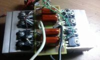
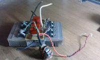
I'm finished building my new QCW DRSSTC bridge. This new parallel bridge was created after I blew my last bridge consisting of 4 IGBT (FGH40N60SMD). Per my records, the last bridge was only capable of handling 150 Amps @ 10ms up +2ms down ramp creating a meter long QCW sword spark (could be longer if branching is minimized/or absent) Fres of my coil is around 300 khz (maybe lower when loaded due to streamers)
CONFIG:
Parallel bridge is consist of 8 FGH40N60SMD IGBTs, estimated to handle not more than 270 Amps max @ 10ms up + 2ms down ramp
SET UP:
When I first tried this parallel bridge, I was getting about HALF of the expected output spark. This was concluded because I changed the specification of the primary circuit by decreasing the impedance of the tank to about half (e.i. old = 60 Ohms, new = 30 ohms) to my assumption that it will double the primary current & hopefully double or at least increase the spark output, BUT, the primary current is still playing at 130 Amp & spark output is still the same (a meter long). My first response is to still lower the impedance, I even went low to a 4 turn primary coil (tank impedance dropped to about 20 ohms) which I think is already extremely low for a QCW DRSSTC system.
I noticed that I'm having problem when I switched back to my original (old) full bridge configuration consisting of only 4 IGBTs. With this old bridge (4 IGBTs), even at low voltage, it easily peaked the current (reaching very high current of about 100 amps only @ 4 ms), I am viewing this primary current waveform via a 100 ohm burdened 100:1 CT & a oscilloscope. Hence, I am convinced that there is something wrong with the parallel full bridge (8 IGBTs).
I suspect that the culprit is in the GDT. As you can see in the images in this thread, I am using only 1 GDT to drive 8 IGBTs, Maybe the GDT cannot drive 8 gates. All of other QCW coils i've seen on the internet have 2 igbts to drive parallel bridges.
Now, I am winding 2 GDTs to drive 8 IGBTs equally (4 gates per GDT).
Question is, I have only 1 power output from my UD, (recent UD versions have 2 outputs for 2 GDTs) can I simply parallel my GDT primaries to get the GDTs working ok?
Any answers/comments in this topic is highly appreciated, thank you in advance.

Re: Parallel Full Bridge (8 switches)
Sulaiman, Mon Dec 22 2014, 11:35AM
Maybe the GDT driver is too 'weak' to hard drive 15 nF of combined gate capacitance?
Sulaiman, Mon Dec 22 2014, 11:35AM
Maybe the GDT driver is too 'weak' to hard drive 15 nF of combined gate capacitance?
Re: Parallel Full Bridge (8 switches)
Goodchild, Mon Dec 22 2014, 12:28PM
I'm not sure why you came to the conclusion that it was the GDT. If the GDT was not driving that gates hard enough you would have other problems like exsesive heating or destruction of the IGBTs. You are likely Q limited on your resonator ie your losses match the resonant rise in the primary & secondary circuit.
Options to try:
Higher bus voltage
lower coupling
secondary MMC to keep fres shift to a minimum and Q Max
Re: Parallel Full Bridge (8 switches)
zzz_julian_zzz, Mon Dec 22 2014, 04:47PM
Thanks for your comments.
To Eric,
V input is same. Coupling is same. If sec capacitance is low, then why is that when I tried to use single Full bridge the primary current easily went up(not changing anything else)? so sec parameter is i think not the problem in this case. The problem is only in the bridge. Again, will the 2 GDTs work if their Primaries are connected in Parallel? Thanks in advance.
Re: Parallel Full Bridge (8 switches)
loneoceans, Mon Dec 22 2014, 08:06PM
Answering your question, primaries in parallel should work fine; make sure you get them phased correctly. That said, I don't see why one GDT won't work even with one GDT output from your UD (one output is good enough to drive a full bridge of CM300s which is harder to drive than the 8 transistors you have.) If your drive was insufficient, your IGBTs would desaturate and get very hot and sad quickly.
Other than the parameters suggested by goodchild, I noticed you have the IGBTs have their gates wired with separate resistors. If I'm not mistaken, the proper way to do this is with a common shared resistor with individual tuned series resistors to make sure the switching waveforms are matched. If you're using cheap 5% resistors they could be up to 10% different from each other. I'd scope the gate waveforms as well to make sure I get the switching I expect. I use 0.5% individual gate resistors for my 8 bridge and they seem to work fine.
I think the reason why people (including myself) use 2 GDTs is probably because it's easier to find small ferrite cores. Well, at least that's the reason why I used two GDTs since I have a bunch of small cores around and I can't fit so many wires around a small core. :) But I might use a single bigger core the next time.
Re: Parallel Full Bridge (8 switches)
zzz_julian_zzz, Tue Dec 23 2014, 04:14PM
HI loneoceans,
thank you. I presume all the percentage (%) mentioned in your post refers to tolerance?
What do you mean by common shared resistor with individual tuned series resistor?
Can I also use 1% tolerance resistor @ 0.25 watts?, 0.5% is not available in my country?
thanks for the help guys..
Re: Parallel Full Bridge (8 switches)
Dr. Dark Current, Tue Dec 23 2014, 05:41PM
I think the gate resistor tolerance plays little role here. The difference in switching times is your main enemy. The best way would be to use 2 primaries (can be wound bifilar) with their tank caps, or small matching inductors in series with each half bridge (small air-cored inductors should do the trick).
If each two paralelled transistors are very close to each other and interconnected by wires as short as possible, then I'd just connect them directly in parallel (done this in a half-wave CWDRSSTC, gates directly in parallel with a single gate resistor, worked all right).
Re: Parallel Full Bridge (8 switches)
Steve Ward, Tue Dec 23 2014, 11:05PM
Make sure the coil is operating in the same mode in all tests. If you tuned to operate at the upper pole frequency, the tuning will be awful for the lower pole frequency performance. So just check that the operating frequency is what you expect in all cases, it may be that your different bridges have different delay times causing the driver to lock to a different mode.
Are you using a driver with phase-lead? Have you checked the IGBT switching vs the load current? QCW can be more sensitive to ZCS because the frequency is high and the switch time is significant. Any delay in switch time results in lower power factor from the bridge, so you are getting less watts per ampere.
Re: Parallel Full Bridge (8 switches)
teravolt, Wed Dec 24 2014, 03:26AM
hi julian. perhaps your transformer cores are saturating what does the rise time of your gates look like?
teravolt, Wed Dec 24 2014, 03:26AM
hi julian. perhaps your transformer cores are saturating what does the rise time of your gates look like?
Re: Parallel Full Bridge (8 switches)
zzz_julian_zzz, Thu Dec 25 2014, 03:30AM
hi Dr. DC, I think too that the Gate resistance is not the culprit here. at the moment, i want to stick with the parallel switches, once I perfected working with them, then I'll try the other driving methods like in one of your recommendation about 2 primaries. Thanks again!
Hi Steve,
unfortunately, I don't have DSO to measure /record frequency shift or F run. about the bridge's delay times, will it really differ much if the same IGBT were being paralleled from just singular? all i use is FGH40N60SMD, so switch times are same i think? and yes, I do use Phase lead driver. Thanks!
Hi teravolt,
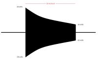
now that you mentioned it, I noticed something from my GDT output. this waveform can be seen on both of my GDTs ( i already implemented dual GDT) The total 10 ms burst drops from 24v to 10 volts. I already added some capacitance 4700uf(adjacent to the power stage mosfets) on the 24v rails - which makes the drive beefier, now it drops to only 15v. But how do I really address this? I have complete filtering on my GDT driver, DC input, regulator's in & out.
Is it on the blocking capacitor? does anybody experienced this also?
zzz_julian_zzz, Thu Dec 25 2014, 03:30AM
I think the gate resistor tolerance plays little role here. The difference in switching times is your main enemy. The best way would be to use 2 primaries (can be wound bifilar) with their tank caps, or small matching inductors in series with each half bridge (small air-cored inductors should do the trick).
If each two paralelled transistors are very close to each other and interconnected by wires as short as possible, then I'd just connect them directly in parallel (done this in a half-wave CWDRSSTC, gates directly in parallel with a single gate resistor, worked all right).
hi Dr. DC, I think too that the Gate resistance is not the culprit here. at the moment, i want to stick with the parallel switches, once I perfected working with them, then I'll try the other driving methods like in one of your recommendation about 2 primaries. Thanks again!
Make sure the coil is operating in the same mode in all tests. If you tuned to operate at the upper pole frequency, the tuning will be awful for the lower pole frequency performance. So just check that the operating frequency is what you expect in all cases, it may be that your different bridges have different delay times causing the driver to lock to a different mode.
Are you using a driver with phase-lead? Have you checked the IGBT switching vs the load current? QCW can be more sensitive to ZCS because the frequency is high and the switch time is significant. Any delay in switch time results in lower power factor from the bridge, so you are getting less watts per ampere.
Hi Steve,
unfortunately, I don't have DSO to measure /record frequency shift or F run. about the bridge's delay times, will it really differ much if the same IGBT were being paralleled from just singular? all i use is FGH40N60SMD, so switch times are same i think? and yes, I do use Phase lead driver. Thanks!
hi julian. perhaps your transformer cores are saturating what does the rise time of your gates look like?
Hi teravolt,
now that you mentioned it, I noticed something from my GDT output. this waveform can be seen on both of my GDTs ( i already implemented dual GDT) The total 10 ms burst drops from 24v to 10 volts. I already added some capacitance 4700uf(adjacent to the power stage mosfets) on the 24v rails - which makes the drive beefier, now it drops to only 15v. But how do I really address this? I have complete filtering on my GDT driver, DC input, regulator's in & out.
Is it on the blocking capacitor? does anybody experienced this also?

Re: Parallel Full Bridge (8 switches)
zzz_julian_zzz, Thu Dec 25 2014, 04:30PM
UPDATE:
Hi guys, found the problem. I can also see that waveform (picture posted above) on the GDT secondary is same with the GDT primary, meaning, the driver's voltage profile is sagging dramatically. I've tried to changed my power supply (from 24v/1amp to 33v/3amps) still, voltage waveform dropping around 15vdc, I think I have to revise my driver. maybe the discreet part of my UD is causing these problems. I'm using this circuit(photo below), i checked the waveform of each point from this circuit and found that at POINT A, this "sagging waveform" already exist, boosting it up 'til reach POINT C (one leg of the GDT primary). I also tried to put a local capacitor adjacent to the rail near POINT A. still Voltage is dropping rapidly. Any ideas how can i resolve this other than redesigning my board using mosfet driver ICs? thanks!
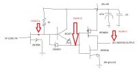
NOTE: IRF9530 (must be top mosfet) IRF640N (must be bottom mosfet) - my mistake wrong placement of mosfets in my drawing.
zzz_julian_zzz, Thu Dec 25 2014, 04:30PM
UPDATE:
Hi guys, found the problem. I can also see that waveform (picture posted above) on the GDT secondary is same with the GDT primary, meaning, the driver's voltage profile is sagging dramatically. I've tried to changed my power supply (from 24v/1amp to 33v/3amps) still, voltage waveform dropping around 15vdc, I think I have to revise my driver. maybe the discreet part of my UD is causing these problems. I'm using this circuit(photo below), i checked the waveform of each point from this circuit and found that at POINT A, this "sagging waveform" already exist, boosting it up 'til reach POINT C (one leg of the GDT primary). I also tried to put a local capacitor adjacent to the rail near POINT A. still Voltage is dropping rapidly. Any ideas how can i resolve this other than redesigning my board using mosfet driver ICs? thanks!

NOTE: IRF9530 (must be top mosfet) IRF640N (must be bottom mosfet) - my mistake wrong placement of mosfets in my drawing.
Re: Parallel Full Bridge (8 switches)
Dr. Dark Current, Fri Dec 26 2014, 04:27PM
Hi, I can see 2 problems in the schematic you posted:
1) The P- and N-channel MOSFETs are swapped. The P-channel one must have its source connected to the +V, the N-channel one has its source connected to GND. Replace the transistors with new ones and in the correct position.
2) The maximum supply voltage for this circuit is 20 VDC.
-Jan
Re: Parallel Full Bridge (8 switches)
Steve Conner, Fri Dec 26 2014, 05:37PM
I think the MOSFETs are deliberately used as inverters here, not source followers. Neither way will work that well.
Steve Conner, Fri Dec 26 2014, 05:37PM
I think the MOSFETs are deliberately used as inverters here, not source followers. Neither way will work that well.
Re: Parallel Full Bridge (8 switches)
Dr. Dark Current, Fri Dec 26 2014, 06:02PM
It works good enough with the transistors connected as "inverters". Good decoupling and not-too-low-Rdson transistors are required to decrease supply voltage ripple and shoot-through current. I know of some people who used this circuit with success.
However with a slight modification (eg. connecting the gate turn on/off resistors in series with the drains) it would be a cleaner solution.
Re: Parallel Full Bridge (8 switches)
teravolt, Fri Dec 26 2014, 07:51PM
add 1000 to 2200 uf to your 24v power supply as close as pausible as you can to your driver. also double the size of your GDT so that it won't saturate and then look at it again. You may have more capacitance to the 24v. One danger though pay attention to the temperature of GDT driver fets. the on resistance is 54m ohm and should stay cool
Re: Parallel Full Bridge (8 switches)
zzz_julian_zzz, Sat Dec 27 2014, 03:37PM
Hi Jan,
You are right, the MOSFETS were mistakenly swapped in the drawing, but in my circuit it is correct (e.i. P channel's Source pin connected to V+ and Drain Pin is connected to output/tied w/ N channel's Drain pin & its source pin connected to GND).
I used this circuit up to 30volts without any issues. I haven't tried that (gate turn on/off resistors in series with the drains) maybe i'll give some other time to test that too. thank you!
Hi Steve Conner,
you are correct indeed, MOSFETs here used as Current Boosters/inverter (logic). But i think there will be some issues if D & S legs were swapped, though i haven't tested it yet. Thanks!
Hi Teravolt,
Yeah, I already done that, putting large capacitance "adjacent" to the 24v rail/of the MOSFETs with some decoupling ones.
Still, Voltage drops dramatically to ~ 15 volts. Thank you.
zzz_julian_zzz, Sat Dec 27 2014, 03:37PM
Hi, I can see 2 problems in the schematic you posted:
1) The P- and N-channel MOSFETs are swapped. The P-channel one must have its source connected to the +V, the N-channel one has its source connected to GND. Replace the transistors with new ones and in the correct position.
2) The maximum supply voltage for this circuit is 20 VDC.
It works good enough with the transistors connected as "inverters". Good decoupling and not-too-low-Rdson transistors are required to decrease supply voltage ripple and shoot-through current. I know of some people who used this circuit with success.
However with a slight modification (eg. connecting the gate turn on/off resistors in series with the drains) it would be a cleaner solution.
Hi Jan,
You are right, the MOSFETS were mistakenly swapped in the drawing, but in my circuit it is correct (e.i. P channel's Source pin connected to V+ and Drain Pin is connected to output/tied w/ N channel's Drain pin & its source pin connected to GND).
I used this circuit up to 30volts without any issues. I haven't tried that (gate turn on/off resistors in series with the drains) maybe i'll give some other time to test that too. thank you!
I think the MOSFETs are deliberately used as inverters here, not source followers. Neither way will work that well.
Hi Steve Conner,
you are correct indeed, MOSFETs here used as Current Boosters/inverter (logic). But i think there will be some issues if D & S legs were swapped, though i haven't tested it yet. Thanks!
add 1000 to 2200 uf to your 24v power supply as close as pausible as you can to your driver. also double the size of your GDT so that it won't saturate and then look at it again. You may have more capacitance to the 24v. One danger though pay attention to the temperature of GDT driver fets. the on resistance is 54m ohm and should stay cool
Hi Teravolt,
Yeah, I already done that, putting large capacitance "adjacent" to the 24v rail/of the MOSFETs with some decoupling ones.
Still, Voltage drops dramatically to ~ 15 volts. Thank you.
Re: Parallel Full Bridge (8 switches)
Andy, Sat Dec 27 2014, 11:24PM
Hi, I think its 8 times 2volt voltage drop of the diodes, are you using a module or a seprate transitor. They might have one biult in.
Hope it helps
Andy
Andy, Sat Dec 27 2014, 11:24PM
Hi, I think its 8 times 2volt voltage drop of the diodes, are you using a module or a seprate transitor. They might have one biult in.
Hope it helps
Andy
Re: Parallel Full Bridge (8 switches)
zzz_julian_zzz, Sun Dec 28 2014, 12:26AM
Hi Andy,
Thanks for your comment. No there are no 2v drop diode in the circuit, I use 1n5819 schottky diodes so (if there is) the V drop across diode is very little (not reaching 2volts i think). I almost forgot, when I use the circuit above on my previous SSTCs / DRSSTCs I saw no problems on the gates, meaning, there are almost no V drop (all approx 24v )- i think this is because of the very short ON-TIME of about <200 us. Gate waveforms can be seen as almost perfect squares. Not same scenario with the QCWDRSSTC with the on-time reaching extremely to 20ms.
I honestly think that the MOSFET in the level shifting stage (2N7000) with pull up resistor is causing this V drop. today, I'm going to replace it with a new one and then I'll check if it will work. I'll also try changing the value of the 1k resistor but I believe I'm also playing the Rise/Fall time of the level shifting/ and of course the overall switching.
Or maybe, the BC337 NPN is causing this drop due to higher current requirement on its base with the playing frequency of 350~400 khz. I'll try replacing it too, or putting a base resistor in it. I'll post the results sooner. Thanks!
zzz_julian_zzz, Sun Dec 28 2014, 12:26AM
Andy wrote ...
Hi, I think its 8 times 2volt voltage drop of the diodes, are you using a module or a seprate transitor. They might have one biult in.
Hope it helps
Andy
Hi, I think its 8 times 2volt voltage drop of the diodes, are you using a module or a seprate transitor. They might have one biult in.
Hope it helps
Andy
Hi Andy,
Thanks for your comment. No there are no 2v drop diode in the circuit, I use 1n5819 schottky diodes so (if there is) the V drop across diode is very little (not reaching 2volts i think). I almost forgot, when I use the circuit above on my previous SSTCs / DRSSTCs I saw no problems on the gates, meaning, there are almost no V drop (all approx 24v )- i think this is because of the very short ON-TIME of about <200 us. Gate waveforms can be seen as almost perfect squares. Not same scenario with the QCWDRSSTC with the on-time reaching extremely to 20ms.
I honestly think that the MOSFET in the level shifting stage (2N7000) with pull up resistor is causing this V drop. today, I'm going to replace it with a new one and then I'll check if it will work. I'll also try changing the value of the 1k resistor but I believe I'm also playing the Rise/Fall time of the level shifting/ and of course the overall switching.
Or maybe, the BC337 NPN is causing this drop due to higher current requirement on its base with the playing frequency of 350~400 khz. I'll try replacing it too, or putting a base resistor in it. I'll post the results sooner. Thanks!
Re: Parallel Full Bridge (8 switches)
teravolt, Tue Dec 30 2014, 02:47AM
hi Julian, I was thinking is it pausable that your transformer core is saturating or it doesn't have the proper frequency response? If it saturates the transformer would look like a short. would a series resistor with the say 10 ohms help. I don't think there is any thing is wrong with your circuit. Does your 24v sag with your waveform? I wouldn't think driving all 8 gates would drop 1000 uf that badly. If you disconnected a couple gates does your wave form sag less?
Re: Parallel Full Bridge (8 switches)
zzz_julian_zzz, Wed Dec 31 2014, 03:45AM
Hi teravolt,
yes, without the GDT(secondary loaded with 220nf - total to all 4 secondary) the 24v supply rail sags (LESS) means, with or without GDT, 10ms ON time is something that a 24v/1A regulator 7824 cannot supply anymore, I've checked the regulator's input and output, and found that there is still plenty of voltage available in the input but the regulator cannot keep up on the output/and is of course heating badly. I'm currently designing a SMPS to replace the ol' 24v transfomer/24v regulator power supply scheme. hopefully this will solve my problem.
I'll post the results soon but in the mean time, happy new year everybody! Thanks!
Re: Parallel Full Bridge (8 switches)
teravolt, Wed Dec 31 2014, 05:22AM
hi Julian, is it possible that the FET's are shooting through? I would think that there would be no load on the 24v with out the transformer. how about this.
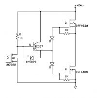
teravolt, Wed Dec 31 2014, 05:22AM
hi Julian, is it possible that the FET's are shooting through? I would think that there would be no load on the 24v with out the transformer. how about this.

Re: Parallel Full Bridge (8 switches)
teravolt, Wed Dec 31 2014, 05:34AM
or
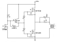
I also found a website that has some more circuit ideas

teravolt, Wed Dec 31 2014, 05:34AM
or

I also found a website that has some more circuit ideas

Re: Parallel Full Bridge (8 switches)
zzz_julian_zzz, Wed Jan 07 2015, 09:46AM
Hi Teravolt,
Thank you for the schematic you posted, however, is the tied output really Source Pin of P channel MOSFET & Drain of the N Channel MOSFET? Would it swing rail to rail? Thanks in advance.
zzz_julian_zzz, Wed Jan 07 2015, 09:46AM
Hi Teravolt,
Thank you for the schematic you posted, however, is the tied output really Source Pin of P channel MOSFET & Drain of the N Channel MOSFET? Would it swing rail to rail? Thanks in advance.
Re: Parallel Full Bridge (8 switches)
teravolt, Wed Jan 07 2015, 05:16PM
i might of had the out put fets swaped. iwas in a hury
teravolt, Wed Jan 07 2015, 05:16PM
i might of had the out put fets swaped. iwas in a hury
Print this page