
Driving a Igbt
Andy, Sat Dec 20 2014, 08:42PMHi, i've been looking at discharging a capacitor quickly, and would like 600V at roughly 400A max values, with a on-offtime in 1000th/ms and a rep rate of 1ms.
Found this on Mouser
 Would that fit the requirements.
I don't know how to drive them, are they like Mosfets or transistors, if I was going to discharge a cap, can I have one on the forward side and reverse of the capacitor?
Cheers
Re: Driving a Igbt
BigBad, Sat Dec 20 2014, 09:53PM
You drive IGBTs very much like a mosfet, they have the insulated gate/base but they have transistor-like transfer characteristics.
BigBad, Sat Dec 20 2014, 09:53PM
You drive IGBTs very much like a mosfet, they have the insulated gate/base but they have transistor-like transfer characteristics.
Re: Driving a Igbt
Andy, Tue Dec 23 2014, 03:49AM
Thanks, I don't were I picked it up, but I thought the gate had(in the eg) to be 20volt above the source.
For Duel modules, do you double the specs, or is the specs take that into account(I'm assuming its just two wired in parallel)
If you are quickly discharging a capacitor, do you have to turn off the switch thats from the source to the cap, before you open the switch through the load, or can they be at the same time(aiming for longlife).
Cheers
Andy
Re: Driving a Igbt
hen918, Tue Dec 23 2014, 05:37AM
The double ones are often two seperate IGBTs in the same module. In some of them, the drain of one is connected internally to the source of the other.
The IGBTs are usually designed to operate with a MAX voltage of 20v. 18v is a safe voltage to go for, in that case.
hen918, Tue Dec 23 2014, 05:37AM
The double ones are often two seperate IGBTs in the same module. In some of them, the drain of one is connected internally to the source of the other.
The IGBTs are usually designed to operate with a MAX voltage of 20v. 18v is a safe voltage to go for, in that case.
Re: Driving a Igbt
Andy, Tue Dec 23 2014, 08:16PM
Thanks hen918
I've drawing up a schemtic of the setup, that I think will work, is there any parts that need adding or subtracting.
Cheers
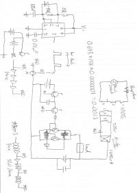
Andy, Tue Dec 23 2014, 08:16PM
Thanks hen918
I've drawing up a schemtic of the setup, that I think will work, is there any parts that need adding or subtracting.
Cheers

Re: Driving a Igbt
Kolas, Sat Jan 10 2015, 11:27AM
The modules are usually in fact a half bridge (in series) and would be totally useless for this application unless you needed the V stand off. IGBT's typically have diodes and fast ones anti parallel within the switch it's self. I don't believe this one does! Not great to start with. Paralleling IGBT's for this application is probably going to end badly. I recommend some shunting resitance, or inductance to help assure that one doesn't momentarily attempt to conduct all of the current due to turn on time difference.
If your mot's are wired for 240V and their primaries are in series you still run a big risk of overvolting these igbt's as they do not tolerate voltages over 600 (rarely if at all)
In short: SCR's are more ideal for this application because they are well known for being able to withstand much higher peak currents for the amount of time you're looking at. they can also be seen as a drop in replacement for the IGBT in this case.
Finally it would be a good idea to indeed switch off the charging current before discharging. In this case it probably wouldn't be a cause of failure, but it would be a waste of power.
Re: Driving a Igbt
Andy, Sun Jan 11 2015, 03:54AM
Thanks kolas, looked at a Scr that is in spec, but it says holding current, does that mean I need to source say 200mA but when it detect zero crossing, I can then disable the holding current or does it act like a Fet but I need to supply the amps to keep it on/off?
Thanks
Re: Driving a Igbt
GrantX, Mon Jan 12 2015, 05:53AM
I don't have much experience with SCR's, so there might be some flaws in this description. Hopefully someone with more experience can correct any mistakes ;)
GrantX, Mon Jan 12 2015, 05:53AM
Andy wrote ...
Thanks kolas, looked at a Scr that is in spec, but it says holding current, does that mean I need to source say 200mA but when it detect zero crossing, I can then disable the holding current or does it act like a Fet but I need to supply the amps to keep it on/off?
Thanks
Once you trigger an SCR it will keep conducting until the current drops below it's holding current. If the holding current is 200mA, then the SCR will stay on until the current drops below this point, even if the trigger pulse applied to the gate is very short. When discharging a capacitor the current will ring back and forth (if there's ANY inductance), crossing the zero volt line. If you place a powerful diode in anti-parallel with the SCR this will conduct the reverse voltage and allow the SCR to turn off (so your trigger pulse needs to end before the current from the capacitor reverses).Thanks kolas, looked at a Scr that is in spec, but it says holding current, does that mean I need to source say 200mA but when it detect zero crossing, I can then disable the holding current or does it act like a Fet but I need to supply the amps to keep it on/off?
Thanks
I don't have much experience with SCR's, so there might be some flaws in this description. Hopefully someone with more experience can correct any mistakes ;)
Re: Driving a Igbt
Kolas, Mon Jan 12 2015, 05:15PM
Everything you said is correct grant. I personally have very little practical experience using SCRs in this particular fasion, but the theory remains valid. Once you remove the current to the gate the SCR will stay on until the latching current drops below the specified value. I would suggest getting two identical SCRs and and wiring them in anti parallel. You can easily find SCRs in one package that meets this description (triac). Then, you have reverse voltage spike protection while still getting the functionality you desire. If it were me, I'd leave the gate current on until the ringing is over so that neither device ever has to see a large spike stress. This should be pretty desirable unless your caps cannot handle some voltage reversal(which may be the case) OR you wish to attempt to recover the remaining energy (which would be tough.)
Re: Driving a Igbt
Andy, Mon Jan 12 2015, 05:57PM
Thanks Grant and Kolas.
Do you think if I have a Scr on the postive side of a cap, when it gets allmostcharged, the scr switchs off, allowing the cap to be discharge?
Im thinking that if the leakage current of the ccapacitor is less than the holding current it might work.
Re: Driving a Igbt
Kolas, Mon Jan 12 2015, 06:10PM
haha i never thought of that but yes! that will work!! very cool. remember that isolated power will be needed for all of these gates.
Kolas, Mon Jan 12 2015, 06:10PM
haha i never thought of that but yes! that will work!! very cool. remember that isolated power will be needed for all of these gates.
Re: Driving a Igbt
Andy, Sun Jan 18 2015, 06:21AM
Kolas, with the isolation is that optocoulpes for driving ics?
Something along the same lines but different part of the circuit, im trying to workout or understand pnp mosfets, I dont really understand the below picture with recards the to resistors, the divided voltage is 1.812 volts on the gate?
Cheers
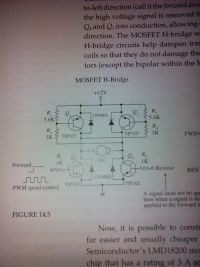
With the mosfet instead of switchs.
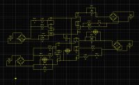
Andy, Sun Jan 18 2015, 06:21AM
Kolas, with the isolation is that optocoulpes for driving ics?
Something along the same lines but different part of the circuit, im trying to workout or understand pnp mosfets, I dont really understand the below picture with recards the to resistors, the divided voltage is 1.812 volts on the gate?
Cheers

With the mosfet instead of switchs.

Re: Driving a Igbt
mister_rf, Sun Jan 18 2015, 09:15AM
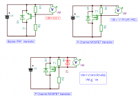
By the way, that’s a bipolar transistor H-bridge.
And in practice there’s a difference for using BJT transistors vs MOSFET transistors.
For BJT normal polarization the base emitter voltage Vbe = around 0.6 volts up to 0.7 volts
Using MOSFET the excessive voltage will punch through the gate-source oxide layer and result in permanent damage. Notice that we need to use a voltage clamp (a conventional zener diode is suitable for this purpose) to prevent the gate-source voltage rating from being exceeded.
The gate – source voltage will not reach more than the zener voltage.

Re: Driving a Igbt
Kolas, Mon Jan 19 2015, 06:05AM
I see lines blurring here somewhat. BJT's do "switch" much differently then igbt's and mosfets to a lesser extent.
For my own purposes I treat both mosfets and igbt's in much the same way; in that they switch from 0 to 1 with very little time. One way to achive this is by what is called a GDT or gate driver transformer.
This is because typically two or more of these switches need to be driven at once, and in that case it is even more often that they need to be switched exactly opposite of each other. Hence the transformer. To get exactly inverted signals, all one must do is flip the polarity of one of the windings. GDT's also provide decent isolation from the gate drive circuitry.
Generally in this case, both igbt's and mosfets should be provided as square a wave as possible so that rise and fall times are short.
It is worth noting that SCR's can also be driven by GDT's, however they trigger, instead of switch.
Optocoupling can also be used, and are certainly getting popular for SMPS design. However it is important to note that they are just non linear signal transistors and can not: A) switch much power B) switch anything without a secondary power source. so at the end of the day, optocouping is probably going to end up being an unnecessary complication.
Your goal was at one point to discharge a bank of capacitors. If that is still your goal, I would like to reiterate my suggestion that you use SCR's over any other type of solid state switch. They can handle much larger impulse currents and have very little in the way of losses. They are also fairly simple to work with and are very robust and forgiving. For an avalanche switch, there is no better suited a device that i know of.
Re: Driving a Igbt
Andy, Mon Jan 19 2015, 01:51PM
Thanks mister rf, I just don,t get the negtive voltage on the gate compared to source, and how to acheive it. I understand you picture were the zener makes a voltage drop going up, but down the resistors make the drop, is that correct?.
Kolas I apprecate your help, and plan on using a Scr for the discharge part throught water, and the can crusher part for magnetic feild, but ive run into a barrier, I would like to get more thrust than one kg per two kilowatts per hour, so trying to make a barrier discharge system to lower the ohms of the discharge part of the circuit throught water.
The goal is 15kv @ 25mA @ 50khz, which if the circuit above works and I can understand p enchered mosfets should do.
Cheers all
Re: Driving a Igbt
Kolas, Mon Jan 19 2015, 04:57PM
To drive a p and n mosfet is the same. Reasons I know for using p channel mosfets are inversion of a signal, and creating a bridge without the need for isolation in a mid level inverter stage. The resistors are for biasing of the gate so that you can operate said devices in their linear region. It is not particularly necessary to drive the mosfet's gate below 0V. It is done so often because over driving causes the switch to switch more reliably and insures faster gate charge dissipation.(I think) It should not be needed at low frequencies with small mosfets that have small gate charge(s.)
Re: Driving a Igbt
Signification, Sat Feb 21 2015, 07:05AM
Andy,
have you ever looked at this guy called SUBCOOLEDHEATPUMP on youtube? You should...all kinds of very clever things from start to finish about how IGBT's work and how to drive them.
And I also prefer SCR's mainly because of their absolutely huge pulse rating for a firing cycle of ~8-10ms. I have a puck type with a pulse rating of 56,000 Amps at 8ms. I plan to use it with a coil gun.
...cool idea about the capacitor-charging / SCR hold-off scheme!
Re: Driving a Igbt
Newton Brawn, Sat Feb 21 2015, 11:16PM
Andy,
Do you mind especify the load characteristics ?
Series Resistance
Capacitance, inductance.
Schematic
Cheers
Newton Brawn, Sat Feb 21 2015, 11:16PM
Andy,
Do you mind especify the load characteristics ?
Series Resistance
Capacitance, inductance.
Schematic
Cheers
Re: Driving a Igbt
Andy, Sun Feb 22 2015, 12:05AM
Hi Newton
Still fine turning the designs, I was going to use a capacitor discharge but for power you need volts, but I only need amps, so will try inductors as some type of buck or trasfomer type.
I dont think a silcon switch would be the best, but will try have a 15 amp fuse to complete the circuit for the inductor, and use silcon switch to discharge a capactor throught the fuse to break the main circuit.
It will only be a one shoot obviously, so still working on it.
Looked on Mouser and there is a 2volt 60amp mains voltage dc to dc converter, but that dreaming getting that at this stage.
Re: Driving a Igbt
fred, Mon Feb 23 2015, 02:11AM
discharging a capacitor quickly
reduce ESR.
the following pic shows one of my experimental fast cap discharge methods. large copper strips reduce resistance.
lots of smaller capacitors reduce resistance and provide for faster discharge/charge times.
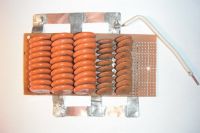
fred, Mon Feb 23 2015, 02:11AM
discharging a capacitor quickly
reduce ESR.
the following pic shows one of my experimental fast cap discharge methods. large copper strips reduce resistance.
lots of smaller capacitors reduce resistance and provide for faster discharge/charge times.

Re: Driving a Igbt
Andy, Mon Feb 23 2015, 05:05AM
Thanks Fred
Apart from way larger capacitance to make the discharge have a flatish curve, do you think theres anonther way?
Reading another thread and Ash Small gave me a brain wave, below pic should have quicker discharge by being in series, with a external field being created, with a one turn salt water as the secondary.
Then again this design might change :( ;)
Re: Driving a Igbt
Andy, Mon Feb 23 2015, 05:05AM
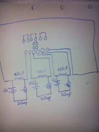
Just think with 20 amp steady state could be boost using quarter of a second and active cooling which should mak 4*2 sqrt = 2.82* 20 amps
Andy, Mon Feb 23 2015, 05:05AM

Just think with 20 amp steady state could be boost using quarter of a second and active cooling which should mak 4*2 sqrt = 2.82* 20 amps
Re: Driving a Igbt
fred, Mon Feb 23 2015, 08:04AM
you should be able to parallel up your lgbt just like any other component to increase your current. i use this for mosfets/regulators when i need more juice or worry about heat. distribute your heat and load.
I was also thinking of either mineral oil or baby oil for insulating and cooling rapidly heating components (like lgbt & mosfets), volume of liquid container... or things like (thermoelectric) peltier junction coolers
what kind of coils are you using? is it cored? toroid?
fred, Mon Feb 23 2015, 08:04AM
you should be able to parallel up your lgbt just like any other component to increase your current. i use this for mosfets/regulators when i need more juice or worry about heat. distribute your heat and load.
I was also thinking of either mineral oil or baby oil for insulating and cooling rapidly heating components (like lgbt & mosfets), volume of liquid container... or things like (thermoelectric) peltier junction coolers

what kind of coils are you using? is it cored? toroid?
Re: Driving a Igbt
Andy, Tue Feb 24 2015, 08:45AM
Will have to build them but looking at a rought spec of 400 amps 0.5-1uH, will then add about four or five in series, aiming for about 5-10 joules per block.
Use straight wire inductance foumla should get pretty close to those values.
Will proable make it out of steel, as the frequency wont be a proabling, maybe one to two turns of 50*3 mm plate bar, design with cooling as the main consideration.
Scr can handle the amps, but dont think I can use them in this case.
What would I be looking at to parrellel Igbts, make model of the switch, I think I can do some tests with four lead acid batterys, and learn how to design them
Re: Driving a Igbt
Andy, Wed Feb 25 2015, 04:12AM
Got some gear, will need some moe ipf540n, for paralleling this, I saw from a post early about youtube, and that you need a singal gate drive per mosfet,
Just wondering what other things you need to parallel them
Cheers
Andy, Wed Feb 25 2015, 04:12AM
Got some gear, will need some moe ipf540n, for paralleling this, I saw from a post early about youtube, and that you need a singal gate drive per mosfet,
Just wondering what other things you need to parallel them
Cheers
Re: Driving a Igbt
fred, Thu Feb 26 2015, 09:20AM
The higher the frequency the more need to use ferrite materials, molecular structure of material determines frequency. take a look at magnetic fields switching on iron. this will give you a guess of the heat dissipation.
there are really good magnetic field simulation software available, allows you to build your device and test it for any parameters. like temperature and field strength etc... lots of good electronic workbench programs do this too. you can then simulate everything and test it before building it.
electronic workbench programs

free magnetic mapping tool

Also- i would build a single demo one just for testing and working out the bugs... get all the bugs worked out on one single thing...write down all your values and play to make it better before moving on. makes everything easier. also saves the wallet...
i find "google images" for finding circuits to be very valuable, i can easily spent hours looking at circuits...
do a search for - igbt. scr and mosfet parallel circuits to give you ideas.
fred, Thu Feb 26 2015, 09:20AM
The higher the frequency the more need to use ferrite materials, molecular structure of material determines frequency. take a look at magnetic fields switching on iron. this will give you a guess of the heat dissipation.
there are really good magnetic field simulation software available, allows you to build your device and test it for any parameters. like temperature and field strength etc... lots of good electronic workbench programs do this too. you can then simulate everything and test it before building it.
electronic workbench programs

free magnetic mapping tool

Also- i would build a single demo one just for testing and working out the bugs... get all the bugs worked out on one single thing...write down all your values and play to make it better before moving on. makes everything easier. also saves the wallet...
i find "google images" for finding circuits to be very valuable, i can easily spent hours looking at circuits...
do a search for - igbt. scr and mosfet parallel circuits to give you ideas.
Re: Driving a Igbt
Andy, Fri Feb 27 2015, 07:06PM
Thanks Fred
Search on google, and noticed something thats strange, why does parallel mosfet driven with a series gate signal, with resistor between each mosfet in the chain.
How would you select the value, is it just to stop inrush current? Wouldnt it make a voltage divider, or is that the reason to balance the voltage?
Cheers
Print this page