
Propeller Physics and VABs Program.
Patrick, Sat Nov 15 2014, 05:42AMIve got permission to use VABs but the link expired since Purdue university hosting service went into the trash can. the AnalSwift company has told me how to get going again, and ive foun the PDF manual.
in a few days theyll release a link and ill start loading prop sections in. There is a problem however, i dont know how to use matrix math.
PDF:
]vabsmanual.pdf[/file]
Re: Propeller Physics and VABs Program.
Sulaiman, Sat Nov 15 2014, 08:10AM
just had a quick skim through of the VABs manual
and I don't see how it will help your uav design much;
. it will not help at all with propellor shape/speed/size design
. the static stresses on the airframe are negligible compared to landing/crashing
(to simulate all variables is impractical)
. even if you could work out optimal profiles for beams etc.
you are stuck with commercially available shapes (uniform rods, tubes, slabs etc.)
I guess you will have to rely on;
. experience of others
. intuition
. field trials
Re: Propeller Physics and VABs Program.
Shrad, Sat Nov 15 2014, 09:58AM
for matrix math you can have a look at scipy which is a matlab equivalent in python...
Shrad, Sat Nov 15 2014, 09:58AM
for matrix math you can have a look at scipy which is a matlab equivalent in python...
Re: Propeller Physics and VABs Program.
Ash Small, Sat Nov 15 2014, 12:38PM
I've just looked at the VABS manual too, and it does look a bit disappointing. It would appear from first glance that it is only useful for working out the stresses in a 'pre-defined' propeller blade, as opposed to helping to arrive at a blade design.
I'm not sure yet whether we can input different designs and then compare lift generated in various scenarios, as there is a relationship between the lift generated and stresses within the blade.
To elaborate, if it predicts the 'bending moment' at the blade root, then this is proportional (if not equal to) the lift generated by the blade. and this could be very useful when comparing different blade designs under different conditions
I don't think it tells us anything about losses associated with disc area, etc., however I'm not sure about this, as the 'downward force' exerted by the propeller is equal to the 'upward force' of the accelerated column of air.
This certainly requires a bit more thought.
Ash Small, Sat Nov 15 2014, 12:38PM
I've just looked at the VABS manual too, and it does look a bit disappointing. It would appear from first glance that it is only useful for working out the stresses in a 'pre-defined' propeller blade, as opposed to helping to arrive at a blade design.
I'm not sure yet whether we can input different designs and then compare lift generated in various scenarios, as there is a relationship between the lift generated and stresses within the blade.
To elaborate, if it predicts the 'bending moment' at the blade root, then this is proportional (if not equal to) the lift generated by the blade. and this could be very useful when comparing different blade designs under different conditions

I don't think it tells us anything about losses associated with disc area, etc., however I'm not sure about this, as the 'downward force' exerted by the propeller is equal to the 'upward force' of the accelerated column of air.
This certainly requires a bit more thought.
Re: Propeller Physics and VABs Program.
Patrick, Sat Nov 15 2014, 06:51PM
Is there any fluid flow or prop Sim anyone knows about? I see random things on our great all knowing Google overlord.
EDIT, found this :

Patrick, Sat Nov 15 2014, 06:51PM
Is there any fluid flow or prop Sim anyone knows about? I see random things on our great all knowing Google overlord.
EDIT, found this :

Re: Propeller Physics and VABs Program.
Andy, Sat Nov 15 2014, 09:11PM
If you don't mind waiting 2-3months, I could writre a program to do the simulations, but then back of the note book cacultions, should be enought.
pressure/velocity = volume
velocity^2
pressure = volume
energy in energy out at 100%
In the past did research on wind turbine, which pretty much work in the opposite theory, but a TSR of greater than 1> is more efficiency but, the torgure is low, a high torgue but low efficiency is a there low tip to speed ratio, in other wards,
if you could make high velocity flow, but without the power of two then it would be the most force, but high velocity and air volume, formulas workout to the same value, "1", so the other equation come into play, if you wan't high moverabilty, make the velocity high to make the power change quick, which will make a unstable aircraft, make the velocity slow, will make a stable craft, the power in and out is the same. the one thing above that isn't in the theory is pressure, that can be reality to weight, in which the gradient of the atmosphere changes with alternative, the pressure changes, which relates to a drop in pressure, and there fore weight, but multi formula maths, says that there is more advances in high altitude, as velocity=P/V is easy and P = V2/V is lower so less pressure more volume gets turned into speed, all in all you can't change the energy input, much, but at high altitude, with a good Carma you will get better effect, forgot the back flow from ground hover, which might confuse you if you add it to statical models.
Hope it helps
Re: Propeller Physics and VABs Program.
Ash Small, Sat Nov 15 2014, 09:30PM
You've not taken losses into account here, Andy, which increase as prop size decreases and as air speed increases.
The most efficient is always large diameter and low RPM, and it's pretty much exponential, very similar to the 'drag equation'.
Certainly looks worth downloading, unfortunately, the website appears to have crashed at the moment.
Ash Small, Sat Nov 15 2014, 09:30PM
Andy wrote ...
If you don't mind waiting 2-3months, I could writre a program to do the simulations, but then back of the note book cacultions, should be enought.
pressure/velocity = volume
velocity^2
pressure = volume
energy in energy out at 100%
In the past did research on wind turbine, which pretty much work in the opposite theory, but a TSR of greater than 1> is more efficiency but, the torgure is low, a high torgue but low efficiency is a there low tip to speed ratio, in other wards,
if you could make high velocity flow, but without the power of two then it would be the most force, but high velocity and air volume, formulas workout to the same value, "1", so the other equation come into play, if you wan't high moverabilty, make the velocity high to make the power change quick, which will make a unstable aircraft, make the velocity slow, will make a stable craft, the power in and out is the same. the one thing above that isn't in the theory is pressure, that can be reality to weight, in which the gradient of the atmosphere changes with alternative, the pressure changes, which relates to a drop in pressure, and there fore weight, but multi formula maths, says that there is more advances in high altitude, as velocity=P/V is easy and P = V2/V is lower so less pressure more volume gets turned into speed, all in all you can't change the energy input, much, but at high altitude, with a good Carma you will get better effect, forgot the back flow from ground hover, which might confuse you if you add it to statical models.
Hope it helps
You've not taken losses into account here, Andy, which increase as prop size decreases and as air speed increases.
The most efficient is always large diameter and low RPM, and it's pretty much exponential, very similar to the 'drag equation'.
Certainly looks worth downloading, unfortunately, the website appears to have crashed at the moment.
Re: Propeller Physics and VABs Program.
Patrick, Sat Nov 15 2014, 10:59PM
but i hope SU^2 has a GUI, and DXF import. i cant learn a complicated new program and learn embedded C at the same time.
Patrick, Sat Nov 15 2014, 10:59PM
but i hope SU^2 has a GUI, and DXF import. i cant learn a complicated new program and learn embedded C at the same time.
Re: Propeller Physics and VABs Program.
Ash Small, Sat Nov 15 2014, 11:09PM
Just been doing some maths, Patrick. Can you check my transposition?
I came up with this:
Power required = square root (Force^3 / (4.9 x Area))
Force remains constant while hovering for a fixed mass multicopter, the 4.9 is 4 times density of air, also a constant, so, at a glance you can see that, as area increases, required power decreases.
I transposed it from here:
"Note that these calculations are only valid for when the incoming air is accelerated from a standstill - for example when hovering."
EDIT: Now, if we know the mass of the 'copter, we know the force required for hovering (9.8 Newtons per kg?), so then we just plot a graph of power required against disc area and we have a graph that 'should' tell us something
EDIT2: We also need to know number of rotors (n), and divide mass by n, then multiply power by n, to get total power in Watts, etc.
EDIT3: As Sulaiman pointed out (and as I pointed out in the 'other' thread for a 'heptacopter') for a hexacopter, if the rotors are close enough together, the losses are even less, but I'd like to see a graph for tri-copter against hexacopter of the same mass. The tricopter will presumably have less overall mass, though.
Let's hope that link for SU^2 works again soon.
Ash Small, Sat Nov 15 2014, 11:09PM
Just been doing some maths, Patrick. Can you check my transposition?
I came up with this:
Power required = square root (Force^3 / (4.9 x Area))
Force remains constant while hovering for a fixed mass multicopter, the 4.9 is 4 times density of air, also a constant, so, at a glance you can see that, as area increases, required power decreases.
I transposed it from here:

"Note that these calculations are only valid for when the incoming air is accelerated from a standstill - for example when hovering."
EDIT: Now, if we know the mass of the 'copter, we know the force required for hovering (9.8 Newtons per kg?), so then we just plot a graph of power required against disc area and we have a graph that 'should' tell us something

EDIT2: We also need to know number of rotors (n), and divide mass by n, then multiply power by n, to get total power in Watts, etc.
EDIT3: As Sulaiman pointed out (and as I pointed out in the 'other' thread for a 'heptacopter') for a hexacopter, if the rotors are close enough together, the losses are even less, but I'd like to see a graph for tri-copter against hexacopter of the same mass. The tricopter will presumably have less overall mass, though.
Let's hope that link for SU^2 works again soon.
Re: Propeller Physics and VABs Program.
Andy, Sun Nov 16 2014, 02:25AM
Ash you missed the point about to arrive at
  , the veolicty is to the power, ether reuqires more power input or generators more thrust
Andy, Sun Nov 16 2014, 02:25AM
Ash you missed the point about
 to arrive at
  , the veolicty is to the power, ether reuqires more power input or generators more thrust
Re: Propeller Physics and VABs Program.
Ash Small, Sun Nov 16 2014, 02:53AM
Post edited.
Maybe I missed your point.
Looking at this again, the velocity bit is where all the losses originate. The larger the 'disc area', the lower the velocity for the same 'lift'.
I think this is why the 'v to the power' term disappears.
Is this the point you were making?
EDIT: It also states that "the "efficiency" of an otherwise-perfect thruster, is proportional to the area of the cross section of the propelled volume of fluid"
Ash Small, Sun Nov 16 2014, 02:53AM
Andy wrote ...
Ash you missed the point about to arrive at
  , the veolicty is to the power, ether reuqires more power input or generators more thrust
Ash you missed the point about
 to arrive at
  , the veolicty is to the power, ether reuqires more power input or generators more thrust
Post edited.
Maybe I missed your point.
Looking at this again, the velocity bit is where all the losses originate. The larger the 'disc area', the lower the velocity for the same 'lift'.
I think this is why the 'v to the power' term disappears.
Is this the point you were making?
EDIT: It also states that "the "efficiency" of an otherwise-perfect thruster, is proportional to the area of the cross section of the propelled volume of fluid"
Re: Propeller Physics and VABs Program.
Ash Small, Mon Nov 17 2014, 03:57AM
Sorry about the double post, but new information:
Ok, 102g requires 1N (1kG/9.81) and 1kG requires 9.81N
9.81^3 = 944
944/(4.9x0.5m^2) = 385
square root 385 = 19W
With 1m^2 disc area, power required is 13.9W
With 2m^2 disc area power required is (Curiously) 9.81W
These figures don't take into account any other losses in the system, but they do demonstrate the point. They are all based on total 'copter mass of 1kg, with a single rotor.
So, in this case, quadrupling the disc area halves the power required, which doubles the flight time.
31.5 inch dia rotor gives 0.5m^2 disc area
and 63 inch diameter rotor gives 2m^2 disc area
We just need to calculate for some more realistic figures.
Re: Propeller Physics and VABs Program.
Patrick, Mon Nov 17 2014, 10:03PM
I cant figure out how to use this software,(SU^2) its a .tgz , which i un-compressed, but i dont know which file to use?
there appears to be know .exe , so do i have to compile this ?

And...

Patrick, Mon Nov 17 2014, 10:03PM
I cant figure out how to use this software,(SU^2) its a .tgz , which i un-compressed, but i dont know which file to use?
there appears to be know .exe , so do i have to compile this ?


And...

Re: Propeller Physics and VABs Program.
Shrad, Tue Nov 18 2014, 08:18AM
linux program which is to be compiled ;)
Shrad, Tue Nov 18 2014, 08:18AM
linux program which is to be compiled ;)
Re: Propeller Physics and VABs Program.
Patrick, Tue Nov 18 2014, 08:38AM
So how do I compile the windows version? is it 32 or 64 bits ?
Patrick, Tue Nov 18 2014, 08:38AM
So how do I compile the windows version? is it 32 or 64 bits ?
Re: Propeller Physics and VABs Program.
Patrick, Wed Nov 26 2014, 03:55AM
 im wondering how to use these, or how to choose one.
i may just use this one.
i cant get this to work on my computer : its got all kinds of instructions and possibilities scattered on his pages. i just need one java method that will work.
EDIT: i may have it working...
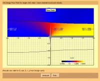
im not sure what the Vx and Vt numbers mean, but the graph and gradient are amazing.
Patrick, Wed Nov 26 2014, 03:55AM
 im wondering how to use these, or how to choose one.
 i may just use this one.

i cant get this to work on my computer :
 its got all kinds of instructions and possibilities scattered on his pages. i just need one java method that will work.
 EDIT: i may have it working...

im not sure what the Vx and Vt numbers mean, but the graph and gradient are amazing.
Re: Propeller Physics and VABs Program.
Shrad, Wed Nov 26 2014, 08:15AM
glad you have sorted this out,
if you have to use a linux program you can always create a virtual machine and install a small linux distribution like debian
it's a project on its own but you can repurpose it as a scientific computation machine by installing python and scipy
along with some µC able to run python and communicate with a host PC in python, this could prove as useful as a labview setup
Re: Propeller Physics and VABs Program.
Patrick, Wed Nov 26 2014, 10:26AM
im thinking of buying one of these 18 inch props then utting it in pieces. one piece form the tip and so on to the hub. while measuring the critical dimensions. however scaling with fluids always worries me. but going from a 18 to a 26 incher wouldnt be as sketchy as scaling from 10 to 26.
its tempting to make a mold using my 3D printer, and lay up props out of CF. those 26 - 29 inch props are just to expensive to be putting into a tree.
Patrick, Wed Nov 26 2014, 10:26AM
im thinking of buying one of these 18 inch props
 then utting it in pieces. one piece form the tip and so on to the hub. while measuring the critical dimensions. however scaling with fluids always worries me. but going from a 18 to a 26 incher wouldnt be as sketchy as scaling from 10 to 26.
its tempting to make a mold using my 3D printer, and lay up props out of CF. those 26 - 29 inch props are just to expensive to be putting into a tree.
Re: Propeller Physics and VABs Program.
Ash Small, Wed Nov 26 2014, 03:58PM
The other option would be to put a series of 'theoretical' dimensions into a 3D CAD package, and then produce a 'net'. From this you could program a 3D printer to produce a mold.
Ash Small, Wed Nov 26 2014, 03:58PM
The other option would be to put a series of 'theoretical' dimensions into a 3D CAD package, and then produce a 'net'. From this you could program a 3D printer to produce a mold.
Re: Propeller Physics and VABs Program.
Patrick, Wed Nov 26 2014, 09:24PM
Patrick, Wed Nov 26 2014, 09:24PM
Ash Small wrote ...
The other option would be to put a series of 'theoretical' dimensions into a 3D CAD package, and then produce a 'net'. From this you could program a 3D printer to produce a mold.
i dont get this... elaborate please.The other option would be to put a series of 'theoretical' dimensions into a 3D CAD package, and then produce a 'net'. From this you could program a 3D printer to produce a mold.
Re: Propeller Physics and VABs Program.
Shrad, Thu Nov 27 2014, 08:58AM
model your prop, split in two parts along the most practical axis, apply in negative to a filled box, and obtain a 3D printable mold which you can scale at will
Shrad, Thu Nov 27 2014, 08:58AM
model your prop, split in two parts along the most practical axis, apply in negative to a filled box, and obtain a 3D printable mold which you can scale at will
Re: Propeller Physics and VABs Program.
Uspring, Thu Nov 27 2014, 10:26AM
Uspring, Thu Nov 27 2014, 10:26AM
im not sure what the Vx and Vt numbers mean, but the graph and gradient are amazing.Vx is the horizontal air velocity. I wonder how accurate this simulation is, since it doesn't seem to include the air viscosity. A sudden jump in air velocity e.g. at the boundary of the slip streams tail to the surrounding air looks unlikely.
Re: Propeller Physics and VABs Program.
Ash Small, Thu Nov 27 2014, 04:29PM
Well, theoretically, if we know the disc area and the RPM when hovering, we should be able to work out theoretical airspeed (of the accelerated column).
Theoretically, all the air wants to be at the same velocity (we can discuss this in detail later)
so, at various points from the nub to the tip we can calculated the required 'angle of attack' (I've not taken 'slip' into consideration yet)
once we have a series of angles at various distances from the hub we can plot the shape, and then adjust for NACA profile, or whatever.
Starting from the 'theoretical optimum' should give useful data to enable us to work out slip, and other losses by comparing thrust, RPM and power consumed.
Ash Small, Thu Nov 27 2014, 04:29PM
Patrick wrote ...
Ash Small wrote ...
The other option would be to put a series of 'theoretical' dimensions into a 3D CAD package, and then produce a 'net'. From this you could program a 3D printer to produce a mold.
i dont get this... elaborate please.The other option would be to put a series of 'theoretical' dimensions into a 3D CAD package, and then produce a 'net'. From this you could program a 3D printer to produce a mold.
Well, theoretically, if we know the disc area and the RPM when hovering, we should be able to work out theoretical airspeed (of the accelerated column).
Theoretically, all the air wants to be at the same velocity (we can discuss this in detail later)
so, at various points from the nub to the tip we can calculated the required 'angle of attack' (I've not taken 'slip' into consideration yet)
once we have a series of angles at various distances from the hub we can plot the shape, and then adjust for NACA profile, or whatever.
Starting from the 'theoretical optimum' should give useful data to enable us to work out slip, and other losses by comparing thrust, RPM and power consumed.
Re: Propeller Physics and VABs Program.
Patrick, Tue Dec 02 2014, 04:06AM
for a hovering prop, wouldnt the slip be 100%?
also, the outer radius produces most of the thrust. if this is true, and we go to the tip, then the tip captures the most air mass and accelerates it to the constant screw speed,
Or, does each x posistion of radius capture the same air mass, making up for velocity change with increase picth towrads the root?
EDIT: im really trying to figure out a 0 to x axis (radius) with a 0 to y axis (acceleration) function, im not sure if this is linear or not? i guess i would have to give dimensions for the prop...
Re: Propeller Physics and VABs Program.
Ash Small, Tue Dec 02 2014, 03:23PM
No. The column of air is being accelerated with a force equal to 9.81 newtons per KG of 'copter mass.
(Actually, now you mention it, you may be correct, I'm used to marine props where lift itself isn't a factor, just the boat's velocity. but the same principle applies, I think, because a force is still being generated. (hovering requires a force of 9.81 newtons per kG of 'copter mass)
I think what I actually mean here is the propeller efficiency. I may need to consider this some more.
You still want the accelerated air velocity to be 'theoretically' constant throughout the column, which means that the angle of attack of the propeller has to be greater towards the centre as the propeller velocity is less than at the tip, which travels at a greater velocity. (In practice this isn't the case as losses close to the hub increase with increased angle of attack, but as this produces very little of the 'overall' thrust, we can reduce drag here without unduly affecting overall lift.)
Obviously, a prop with less pitch needs to rotate faster to generate the same force, but we already know you want a thin section rotating fast for efficiency, so you want a fairly shallow pitch (all the 'copter design stuff tells us this)
If the angle at the tip(x) is theta, then the angle at 1/2x has to be 2 x theta, the angle at 3/4x needs to be 1.5 x theta, and the angle at 1/4x needs to be 4 x theta. In order to keep drag low, we need high RPM, so that 4 times theta is still small. (this assumes a constant blede width)
The ratio of radius to circumferance is constant (2 x pi x r, or pi x d),
Ash Small, Tue Dec 02 2014, 03:23PM
Patrick wrote ...
for a hovering prop, wouldnt the slip be 100%?
for a hovering prop, wouldnt the slip be 100%?
No. The column of air is being accelerated with a force equal to 9.81 newtons per KG of 'copter mass.
(Actually, now you mention it, you may be correct, I'm used to marine props where lift itself isn't a factor, just the boat's velocity. but the same principle applies, I think, because a force is still being generated. (hovering requires a force of 9.81 newtons per kG of 'copter mass)
I think what I actually mean here is the propeller efficiency. I may need to consider this some more.
Patrick wrote ...
also, the outer radius produces most of the thrust. if this is true, and we go to the tip, then the tip captures the most air mass and accelerates it to the constant screw speed,
Or, does each x posistion of radius capture the same air mass, making up for velocity change with increase picth towrads the root?
EDIT: im really trying to figure out a 0 to x axis (radius) with a 0 to y axis (acceleration) function, im not sure if this is linear or not? i guess i would have to give dimensions for the prop...
You still want the accelerated air velocity to be 'theoretically' constant throughout the column, which means that the angle of attack of the propeller has to be greater towards the centre as the propeller velocity is less than at the tip, which travels at a greater velocity. (In practice this isn't the case as losses close to the hub increase with increased angle of attack, but as this produces very little of the 'overall' thrust, we can reduce drag here without unduly affecting overall lift.)
Obviously, a prop with less pitch needs to rotate faster to generate the same force, but we already know you want a thin section rotating fast for efficiency, so you want a fairly shallow pitch (all the 'copter design stuff tells us this)
If the angle at the tip(x) is theta, then the angle at 1/2x has to be 2 x theta, the angle at 3/4x needs to be 1.5 x theta, and the angle at 1/4x needs to be 4 x theta. In order to keep drag low, we need high RPM, so that 4 times theta is still small. (this assumes a constant blede width)
The ratio of radius to circumferance is constant (2 x pi x r, or pi x d),
Re: Propeller Physics and VABs Program.
Patrick, Tue Dec 02 2014, 11:26PM
Patrick, Tue Dec 02 2014, 11:26PM
Ash Small wrote ...
You still want the accelerated air velocity to be 'theoretically' constant throughout the column, which means that the angle of attack of the propeller has to be greater towards the centre as the propeller velocity is less than at the tip, which travels at a greater velocity. (In practice this isn't the case as losses close to the hub increase with increased angle of attack, but as this produces very little of the 'overall' thrust, we can reduce drag here without unduly affecting overall lift.)
Obviously, a prop with less pitch needs to rotate faster to generate the same force, but we already know you want a thin section rotating fast for efficiency, so you want a fairly shallow pitch (all the 'copter design stuff tells us this)
If the angle at the tip(x) is theta, then the angle at 1/2x has to be 2 x theta, the angle at 3/4x needs to be 1.5 x theta, and the angle at 1/4x needs to be 4 x theta. In order to keep drag low, we need high RPM, so that 4 times theta is still small. (this assumes a constant blede width)
The ratio of radius to circumferance is constant (2 x pi x r, or pi x d),
this is what I needed to know, sometimes I get it, then lose it all in a blur.You still want the accelerated air velocity to be 'theoretically' constant throughout the column, which means that the angle of attack of the propeller has to be greater towards the centre as the propeller velocity is less than at the tip, which travels at a greater velocity. (In practice this isn't the case as losses close to the hub increase with increased angle of attack, but as this produces very little of the 'overall' thrust, we can reduce drag here without unduly affecting overall lift.)
Obviously, a prop with less pitch needs to rotate faster to generate the same force, but we already know you want a thin section rotating fast for efficiency, so you want a fairly shallow pitch (all the 'copter design stuff tells us this)
If the angle at the tip(x) is theta, then the angle at 1/2x has to be 2 x theta, the angle at 3/4x needs to be 1.5 x theta, and the angle at 1/4x needs to be 4 x theta. In order to keep drag low, we need high RPM, so that 4 times theta is still small. (this assumes a constant blede width)
The ratio of radius to circumferance is constant (2 x pi x r, or pi x d),
Re: Propeller Physics and VABs Program.
Ash Small, Wed Dec 03 2014, 01:16AM
I have read that the limiting factor should be centripetal (or centrifugal, I can't remember the difference offhand, might be the drink ) force acting on the prop, although drag is also a factor, as is the 'bending moment' in the blade itself, but the limiting factor in most 'copter designs is centripetal (or centrifugal) forces.
Also, you want a a thin, lightweight section, and high RPM.
Hope this helps.
EDIT: Centrifugal, I think or is it both, as they act against each other?
Ash Small, Wed Dec 03 2014, 01:16AM
I have read that the limiting factor should be centripetal (or centrifugal, I can't remember the difference offhand, might be the drink
 ) force acting on the prop, although drag is also a factor, as is the 'bending moment' in the blade itself, but the limiting factor in most 'copter designs is centripetal (or centrifugal) forces.
Also, you want a a thin, lightweight section, and high RPM.
Hope this helps.
EDIT: Centrifugal, I think
 or is it both, as they act against each other?
Re: Propeller Physics and VABs Program.
Shrad, Wed Dec 03 2014, 07:59AM
wouldn't it be the component of both vectors and the acceleration?
Shrad, Wed Dec 03 2014, 07:59AM
wouldn't it be the component of both vectors and the acceleration?
Re: Propeller Physics and VABs Program.
Ash Small, Wed Dec 03 2014, 12:00PM
Can you be more specific, please. Are you querying the centripetal/centrifugal bit, or the x axis, y axis bit, or the 'slip' bit?
I don't want to reply to the wrong question
Ash Small, Wed Dec 03 2014, 12:00PM
Shrad wrote ...
wouldn't it be the component of both vectors and the acceleration?
wouldn't it be the component of both vectors and the acceleration?
Can you be more specific, please. Are you querying the centripetal/centrifugal bit, or the x axis, y axis bit, or the 'slip' bit?
I don't want to reply to the wrong question

Re: Propeller Physics and VABs Program.
Shrad, Wed Dec 03 2014, 01:11PM
I was mentioning the centripetal/centrifugal vectors which are of opposite direction, but combines with the acceleration force vector
as I see it, at constant speed acceleration is null, and centripetal/centrifugal forces being of opposite direction and at equilibrium, a propeller designed for those parameters will hold without problem
now accelerate or decelerate, and you combine a third force vector which will induce stress in another direction
I was simply thinking about the system being incomplete without the acceleration force vector, and was actually wondering if I was right or not ;)
Re: Propeller Physics and VABs Program.
Ash Small, Wed Dec 03 2014, 02:38PM
Yes, you are correct, Shrad, and that does become a factor to be taken into consideration when working out the peak forces on the blades, but for now, we're just considering the 'hovering' scenario, as the maths is much simpler.
The point I was making, I think, is that you want to keep the mass of the blades low, as this minimises the centripetal/centrifugal forces.
I suspect that we'll end up with pure CF blades, with no foam, etc. as carbon has huge tensile strength to combat the centripetal/centrifugal forces and will therefore allow the thinnest section, etc. and also facilitate high RPM.
Ash Small, Wed Dec 03 2014, 02:38PM
Shrad wrote ...
I was mentioning the centripetal/centrifugal vectors which are of opposite direction, but combines with the acceleration force vector
as I see it, at constant speed acceleration is null, and centripetal/centrifugal forces being of opposite direction and at equilibrium, a propeller designed for those parameters will hold without problem
now accelerate or decelerate, and you combine a third force vector which will induce stress in another direction
I was simply thinking about the system being incomplete without the acceleration force vector, and was actually wondering if I was right or not ;)
Yes, you are correct, Shrad, and that does become a factor to be taken into consideration when working out the peak forces on the blades, but for now, we're just considering the 'hovering' scenario, as the maths is much simpler.
The point I was making, I think, is that you want to keep the mass of the blades low, as this minimises the centripetal/centrifugal forces.
I suspect that we'll end up with pure CF blades, with no foam, etc. as carbon has huge tensile strength to combat the centripetal/centrifugal forces and will therefore allow the thinnest section, etc. and also facilitate high RPM.
Re: Propeller Physics and VABs Program.
Shrad, Wed Dec 03 2014, 03:20PM
hovering in a controlled environment?
in my point of view hovering is the result of constant acceleration/deceleration in reaction to the environment (wind, turbulence, etc...)
if you account that it's part of the deal, then I think you still have to account these stresses even if they are reduced, as different materials will have different behaviors facing such small and perpetual variations of forces (flexing, vibrating, etc...)
maybe error calculation can help take that into account? I recall from my courses back in the past that it's not that hard to calculate
Re: Propeller Physics and VABs Program.
Ash Small, Wed Dec 03 2014, 07:18PM
That's correct, all that 'bending moments in a beam' stuff is pretty straightforward, but the maths I provided above only applies to hovering, and is for the 'ideal' case. Obviously the blade has to withstand greater forces than when hovering, as, RPM will be higher when ascending, manouvering, etc. The 'hovering in ideal conditions' scenario gives us a good starting point, though.
Manouverability will also require lightweight blades (manouverability will suffer as disc area increases, but as we've already seen from the maths above and from the graph that BigBad posted in the 'other' thread, large disc area is essential for efficiency), in order to accelerate/decelerate the rotors quickly they will have to be as lightweight as possible.
Drag is the other factor that requires a thin blade section.
High RPM does facilitate a small 'angle of attack', but does increase the centripetal/centrifugal forces in the blade. From what I've read about full size 'copters, it's these forces that ultimately determine maximum RPM, as strength is proportional to mass. As the mass of the blade increases, the strength increases, but so do the centripetal/centrifugal forces within it, due to the incresed mass.
Ash Small, Wed Dec 03 2014, 07:18PM
Shrad wrote ...
hovering in a controlled environment?
in my point of view hovering is the result of constant acceleration/deceleration in reaction to the environment (wind, turbulence, etc...)
if you account that it's part of the deal, then I think you still have to account these stresses even if they are reduced, as different materials will have different behaviors facing such small and perpetual variations of forces (flexing, vibrating, etc...)
maybe error calculation can help take that into account? I recall from my courses back in the past that it's not that hard to calculate
That's correct, all that 'bending moments in a beam' stuff is pretty straightforward, but the maths I provided above only applies to hovering, and is for the 'ideal' case. Obviously the blade has to withstand greater forces than when hovering, as, RPM will be higher when ascending, manouvering, etc. The 'hovering in ideal conditions' scenario gives us a good starting point, though.
Manouverability will also require lightweight blades (manouverability will suffer as disc area increases, but as we've already seen from the maths above and from the graph that BigBad posted in the 'other' thread, large disc area is essential for efficiency), in order to accelerate/decelerate the rotors quickly they will have to be as lightweight as possible.
Drag is the other factor that requires a thin blade section.
High RPM does facilitate a small 'angle of attack', but does increase the centripetal/centrifugal forces in the blade. From what I've read about full size 'copters, it's these forces that ultimately determine maximum RPM, as strength is proportional to mass. As the mass of the blade increases, the strength increases, but so do the centripetal/centrifugal forces within it, due to the incresed mass.
Re: Propeller Physics and VABs Program.
Shrad, Wed Dec 03 2014, 07:34PM
how about a really lightweight body, even with foamy material, which would then be dipped in a carbon fiber and resin mix in a very light mix, many times like a lacker?
it would ensure minimal physical weight, maximum surface resistance, and the outer layer would maintain the cohesion of the innards...
Re: Propeller Physics and VABs Program.
Patrick, Wed Dec 03 2014, 07:52PM
with my 3D printer, printing nearly hollow structures, with minimal shear web, ive blown out my tail at 15+ meters above ground as Andrew predicted

These are about 18 inch props, note the root area. its also steep there. (about 80 to 120 us$, for two)
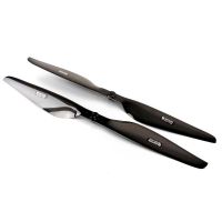
these are 26 inch props, they go all the way up to 29 inch and from 5 to 8 pitch. (about 300 us$ for two)
Patrick, Wed Dec 03 2014, 07:52PM
Shrad wrote ...
how about a really lightweight body, even with foamy material, which would then be dipped in a carbon fiber and resin mix in a very light mix, many times like a lacker?
it would ensure minimal physical weight, maximum surface resistance, and the outer layer would maintain the cohesion of the innards...
The problem is, (as ive layed up many fiberglass, CF and aramid fiber structures), they are already so thin at the mid and outer radius theres' no space for shear web or lightening pockets / foam.how about a really lightweight body, even with foamy material, which would then be dipped in a carbon fiber and resin mix in a very light mix, many times like a lacker?
it would ensure minimal physical weight, maximum surface resistance, and the outer layer would maintain the cohesion of the innards...
with my 3D printer, printing nearly hollow structures, with minimal shear web, ive blown out my tail at 15+ meters above ground as Andrew predicted

These are about 18 inch props, note the root area. its also steep there. (about 80 to 120 us$, for two)

these are 26 inch props, they go all the way up to 29 inch and from 5 to 8 pitch. (about 300 us$ for two)
Re: Propeller Physics and VABs Program.
Shrad, Wed Dec 03 2014, 09:18PM
I guess any handmade one would still be far away from a commercial unit anyway
Shrad, Wed Dec 03 2014, 09:18PM
I guess any handmade one would still be far away from a commercial unit anyway
Re: Propeller Physics and VABs Program.
Ash Small, Wed Dec 03 2014, 10:48PM
Blades specifically designed for the application should out perform anything that is commercially available.
Solid CF gives the the highest strength and lowest drag (and highest RPM, so smallest pitch, thus reducing drag even more)
EDIT: Those blades are designed for high disc loading. They resemble some further down the 'efficiency scale' in the graph in the 'other thread'.
Ash Small, Wed Dec 03 2014, 10:48PM
Shrad wrote ...
I guess any handmade one would still be far away from a commercial unit anyway
I guess any handmade one would still be far away from a commercial unit anyway
Blades specifically designed for the application should out perform anything that is commercially available.
Solid CF gives the the highest strength and lowest drag (and highest RPM, so smallest pitch, thus reducing drag even more)
EDIT: Those blades are designed for high disc loading. They resemble some further down the 'efficiency scale' in the graph in the 'other thread'.
Re: Propeller Physics and VABs Program.
Patrick, Thu Dec 04 2014, 03:57AM
would a symmetric heli blade be better? should we make improvements in that direction? maybe add undercamber to the root side.
Patrick, Thu Dec 04 2014, 03:57AM
Ash Small wrote ...
EDIT: Those blades are designed for high disc loading. They resemble some further down the 'efficiency scale' in the graph in the 'other thread'.
EDIT: Those blades are designed for high disc loading. They resemble some further down the 'efficiency scale' in the graph in the 'other thread'.
would a symmetric heli blade be better? should we make improvements in that direction? maybe add undercamber to the root side.
Re: Propeller Physics and VABs Program.
Ash Small, Thu Dec 04 2014, 04:21PM
Well, the props you posted above certainly look more like the rotors on a V-22 Osprey than conventional 'copter blades.
The V-22 does have high disc loading (even higher than originally planned, as rotor diameter was reduced from 43 feet to 38 feet in order to facilitate below deck storage on carriers).
The kind of prop used on conventional aircraft can be wider with plenty of camber/angle of attack, as it's designed to travel forwards at hundreds of miles per hour, a completely different scenario to hovering, where that design will produce loads of drag.
If we want low disc loading, I think the best approach would be to start with total estimated mass of the 'copter, and number of rotors, then decide on the disc loading we're after, and then see what the disc area of each prop comes out at.
The disc loading on the V-22 is around 100kg/m^2, and power to mass ratio is 427W/kg, compared to the disc loading of Atlas, the human powered helicopter, which is less than 0.1kg/m^2.
It may be worth working out the disc loadind on your existing tri-copter first,
The point I'm making, I suppose, is that the blade design is also dependant on disc loading. It may also be worth looking at the disc loading that the rotors posted above are designed for.
Conventional copters get down to under 20kg/M^2, we should be looking to do better than this, if we're after greater efficiency and longer flight times. (I think we should be aiming for less than 5kg/M^2, maybe even less )
)
EDIT: The Robinson R-22 has a disc loading of 14kg/m^2.
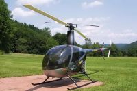
You can see the cross section etc in the photo. Admittedly, this is designed for use with a swashplate, so we may want to include some twist and maybe taper it a bit towards the tip
Ash Small, Thu Dec 04 2014, 04:21PM
Well, the props you posted above certainly look more like the rotors on a V-22 Osprey than conventional 'copter blades.
The V-22 does have high disc loading (even higher than originally planned, as rotor diameter was reduced from 43 feet to 38 feet in order to facilitate below deck storage on carriers).
The kind of prop used on conventional aircraft can be wider with plenty of camber/angle of attack, as it's designed to travel forwards at hundreds of miles per hour, a completely different scenario to hovering, where that design will produce loads of drag.
If we want low disc loading, I think the best approach would be to start with total estimated mass of the 'copter, and number of rotors, then decide on the disc loading we're after, and then see what the disc area of each prop comes out at.
The disc loading on the V-22 is around 100kg/m^2, and power to mass ratio is 427W/kg, compared to the disc loading of Atlas, the human powered helicopter, which is less than 0.1kg/m^2.
It may be worth working out the disc loadind on your existing tri-copter first,
The point I'm making, I suppose, is that the blade design is also dependant on disc loading. It may also be worth looking at the disc loading that the rotors posted above are designed for.
Conventional copters get down to under 20kg/M^2, we should be looking to do better than this, if we're after greater efficiency and longer flight times. (I think we should be aiming for less than 5kg/M^2, maybe even less
 )
)EDIT: The Robinson R-22 has a disc loading of 14kg/m^2.

You can see the cross section etc in the photo. Admittedly, this is designed for use with a swashplate, so we may want to include some twist and maybe taper it a bit towards the tip

Re: Propeller Physics and VABs Program.
Patrick, Thu Dec 04 2014, 10:31PM
ok so lets start this way.
1,430 g AUW.
3 rotors, all 12in diameter, 3.8 pitch, called a "slow-fly" prop.
while moderately maneuvering, a drew 31 amps at about 10.7 volts. from A 3 Ccell lipo (12.6 fully charged, 9.9v discharged)
im also having a battery problem, but we'll deal with that later.
Re: Propeller Physics and VABs Program.
Ash Small, Thu Dec 04 2014, 10:57PM
Thanks for posting the figures. I've had a drink or three, so won't look at it tonight, and I'm pretty busy tomorrow, so may not get round to looking at it until saturday morning. The maths isn't difficult, though, it's all posted above, if you want to look into it before then
Ash Small, Thu Dec 04 2014, 10:57PM
Patrick wrote ...
ok so lets start this way.
1,430 g AUW.
3 rotors, all 12in diameter, 3.8 pitch, called a "slow-fly" prop.
while moderately maneuvering, a drew 31 amps at about 10.7 volts. from A 3 Ccell lipo (12.6 fully charged, 9.9v discharged)
im also having a battery problem, but we'll deal with that later.
ok so lets start this way.
1,430 g AUW.
3 rotors, all 12in diameter, 3.8 pitch, called a "slow-fly" prop.
while moderately maneuvering, a drew 31 amps at about 10.7 volts. from A 3 Ccell lipo (12.6 fully charged, 9.9v discharged)
im also having a battery problem, but we'll deal with that later.
Thanks for posting the figures. I've had a drink or three, so won't look at it tonight, and I'm pretty busy tomorrow, so may not get round to looking at it until saturday morning. The maths isn't difficult, though, it's all posted above, if you want to look into it before then

Re: Propeller Physics and VABs Program.
Ash Small, Fri Dec 05 2014, 07:04AM
I was up early this morning and looked at the figures over a coffee. It only took a couple of minutes to work out the following:
331.7 watts
0.86 m^2
1.66kg/m^2 (disc loading)
232 W/kg
(Maybe someone can check my maths. Maths isn't my strongpoint, especially first thing in the morning)
The disc loading looks ok, but any improvement will still give increased efficiency. I've done a quick calculation on theoretical power required, if there are no losses, and came up with a figure of 32W/kg, so, from the above figures, 200W/kg is being wasted in losses. While we're never going to get close to the 'theoretical' efficiency, and the figures you supplied aren't for hovering in ideal conditions, it does give us a starting point. I think if we can get more data from your test rig, we should be able to get some realistic comparisons of different blade profiles, etc., and extrapolate from there. (It's still early here, I'll need to check the figures etc later. Do we have RPM figures as well? I think you posted some in the other thread when you were using the test rig. Also any data from the manufacturers would be useful regarding RPM, etc. I suspect that the props you used are designed for higher disc loading, and that significant improvements can be made with different profile blades.)
Re: Propeller Physics and VABs Program.
Patrick, Fri Dec 05 2014, 08:22AM
Im thinking that adding a third blade. Even with tip loss, the captured air mass, accelerated less may make up for it.
these current props are 12x3.8
there are 13x4.7, and 14x4.7 props too. I should probly dyno these too.
they did have lists of data, all categorized at rpm intervals, but theyve take it down from their site. ill get them as soon as i can.
Re: Propeller Physics and VABs Program.
Ash Small, Fri Dec 05 2014, 09:33PM
Two blades spinning faster is the same as three blades, assuming you spread the load evenly. You could just be overcomplicating things. 'Copters with more than two blades have very high disc loading, like the V-22 Osprey.
I made a mistake in the maths I posted this morning, I added the disc areas first, instead of dividing the mass by 3. I'll correct it in the morning.
Ash Small, Fri Dec 05 2014, 09:33PM
Patrick wrote ...
Im thinking that adding a third blade. Even with tip loss, the captured air mass, accelerated less may make up for it.
these current props are 12x3.8
there are 13x4.7, and 14x4.7 props too. I should probly dyno these too.
they did have lists of data, all categorized at rpm intervals, but theyve take it down from their site. ill get them as soon as i can.
Two blades spinning faster is the same as three blades, assuming you spread the load evenly. You could just be overcomplicating things. 'Copters with more than two blades have very high disc loading, like the V-22 Osprey.
I made a mistake in the maths I posted this morning, I added the disc areas first, instead of dividing the mass by 3. I'll correct it in the morning.
Re: Propeller Physics and VABs Program.
Patrick, Fri Dec 05 2014, 10:03PM
but dont we want the same thrust from lower tip speed (higher mass)? or does having 3 not change the the mass near the tip exiting near the tip?
Patrick, Fri Dec 05 2014, 10:03PM
Ash Small wrote ...
Two blades spinning faster is the same as three blades, assuming you spread the load evenly.
Two blades spinning faster is the same as three blades, assuming you spread the load evenly.
but dont we want the same thrust from lower tip speed (higher mass)? or does having 3 not change the the mass near the tip exiting near the tip?
Re: Propeller Physics and VABs Program.
Ash Small, Fri Dec 05 2014, 10:44PM
Well, it affects the total mass, if nothing else. Then there's balancing the thing...
Ash Small, Fri Dec 05 2014, 10:44PM
Patrick wrote ...
but dont we want the same thrust from lower tip speed (higher mass)? or does having 3 not change the the mass near the tip exiting near the tip?
Ash Small wrote ...
Two blades spinning faster is the same as three blades, assuming you spread the load evenly.
Two blades spinning faster is the same as three blades, assuming you spread the load evenly.
but dont we want the same thrust from lower tip speed (higher mass)? or does having 3 not change the the mass near the tip exiting near the tip?
Well, it affects the total mass, if nothing else. Then there's balancing the thing...
Re: Propeller Physics and VABs Program.
Shrad, Sat Dec 06 2014, 11:21AM
what about curvy blades to add contact surface with the air? that's another mean of increasing moved air mass, no?
Shrad, Sat Dec 06 2014, 11:21AM
what about curvy blades to add contact surface with the air? that's another mean of increasing moved air mass, no?
Re: Propeller Physics and VABs Program.
Ash Small, Sat Dec 06 2014, 01:20PM
Curvy blades, as you call them, increase drag, if they have too much 'curve'. You'll get eddy currents behind the blade. With marine props, you can get a state where you get cavities of vacuum behind the blades. This situation is called 'cavitation' and is generally detrimental. It can also cause pitting of the prop, which can be very detrimental.
So called 'super-cavitationg' props used for offshore powerboat racing exploit this phenomenon, with the back of the prop running in air or vacuum to reduce drag on the back of the prop, but these are still less than 50% efficient, compared to a well designed ship propeller, which can be over 90% efficient.
This is something we need to consider here, in order to get an efficient design, the blades need to disturb the air as little as possible in order to reduce drag. The air should flow over the blade, without turbulence being created in the 'wake' of the blade. Any turbulence here represents losses.
At least, that's my understanding
Ash Small, Sat Dec 06 2014, 01:20PM
Shrad wrote ...
what about curvy blades to add contact surface with the air? that's another mean of increasing moved air mass, no?
what about curvy blades to add contact surface with the air? that's another mean of increasing moved air mass, no?
Curvy blades, as you call them, increase drag, if they have too much 'curve'. You'll get eddy currents behind the blade. With marine props, you can get a state where you get cavities of vacuum behind the blades. This situation is called 'cavitation' and is generally detrimental. It can also cause pitting of the prop, which can be very detrimental.
So called 'super-cavitationg' props used for offshore powerboat racing exploit this phenomenon, with the back of the prop running in air or vacuum to reduce drag on the back of the prop, but these are still less than 50% efficient, compared to a well designed ship propeller, which can be over 90% efficient.
This is something we need to consider here, in order to get an efficient design, the blades need to disturb the air as little as possible in order to reduce drag. The air should flow over the blade, without turbulence being created in the 'wake' of the blade. Any turbulence here represents losses.
At least, that's my understanding

Re: Propeller Physics and VABs Program.
Andy, Sat Dec 06 2014, 07:37PM
Hi Patrick, just being doing something and have a couple of ideas.
Have a prop at the top with deep pitch slow rpm, then one,two,three below with faster and faster rpm but less pitch.
have a by-pass vent for the top prop that is pressure controlled, normal closed but as wind movement etc happens it gets forced open.
Have two gearboxes 2 motors and four prop would probable be effeinct.
sometimes birds fly in a "u" shape to go in level flight, maybe use fly-by-wire to program effeinct movements for x-z plane, but use the y plane differently.
Don't design the UAV for hovering but more effeinct for movement.
A couple of cents :)

Re: Propeller Physics and VABs Program.
Patrick, Mon Dec 08 2014, 02:29AM
one guy is using pipe, then cutting it off to make his own props.
 composite parts.
 pipe cut props.
 odd one.
Someone says just about any prop can be 70% or so efficient. Since were approaching 100% as an asymptote, eventually theres no advantage in going all out for that last 1%. (im tipsy so this was probly said already) So lets find out what the efficiency of the APC 10, 11, 12 and 13 MR's are, then we'll see how much margin is at stake.
APC has all these numbers, just waiting for re-posting them.
Patrick, Mon Dec 08 2014, 02:29AM
one guy is using pipe, then cutting it off to make his own props.
 composite parts.
 pipe cut props.
 odd one.
Someone says just about any prop can be 70% or so efficient. Since were approaching 100% as an asymptote, eventually theres no advantage in going all out for that last 1%. (im tipsy so this was probly said already) So lets find out what the efficiency of the APC 10, 11, 12 and 13 MR's are, then we'll see how much margin is at stake.
APC has all these numbers, just waiting for re-posting them.
Re: Propeller Physics and VABs Program.
Ash Small, Mon Dec 08 2014, 12:36PM
Well, I don't know how the bloke in the first link is getting 60PSI of vacuum. 15PSI is the limit of all conventional vacuum systems
I think we discussed laying up on a cylindrical form before. You still need to consider leading and trailing edges, etc.
I'm still of the opinion that all of those commercially available props are designed for much higher disc loadings than we want, so will be inefficient at low disc loadings.
I think we need to consider RPM next, once we know that we should be able to do some initial calculations on blade profile, angle of attack, etc.
Ash Small, Mon Dec 08 2014, 12:36PM
Patrick wrote ...
one guy is using pipe, then cutting it off to make his own props.
 composite parts.
 pipe cut props.
 odd one.
Someone says just about any prop can be 70% or so efficient. Since were approaching 100% as an asymptote, eventually theres no advantage in going all out for that last 1%. (im tipsy so this was probly said already) So lets find out what the efficiency of the APC 10, 11, 12 and 13 MR's are, then we'll see how much margin is at stake.
APC has all these numbers, just waiting for re-posting them.
one guy is using pipe, then cutting it off to make his own props.
 composite parts.
 pipe cut props.
 odd one.
Someone says just about any prop can be 70% or so efficient. Since were approaching 100% as an asymptote, eventually theres no advantage in going all out for that last 1%. (im tipsy so this was probly said already) So lets find out what the efficiency of the APC 10, 11, 12 and 13 MR's are, then we'll see how much margin is at stake.
APC has all these numbers, just waiting for re-posting them.
Well, I don't know how the bloke in the first link is getting 60PSI of vacuum. 15PSI is the limit of all conventional vacuum systems

I think we discussed laying up on a cylindrical form before. You still need to consider leading and trailing edges, etc.
I'm still of the opinion that all of those commercially available props are designed for much higher disc loadings than we want, so will be inefficient at low disc loadings.
I think we need to consider RPM next, once we know that we should be able to do some initial calculations on blade profile, angle of attack, etc.

Re: Propeller Physics and VABs Program.
Patrick, Mon Dec 08 2014, 06:19PM
That "Test Pilot Mafia" guy... thats me .
.
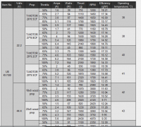
Various configurations. It seems they dont want CF props to see more than 22.2 V, the wood props are rated to 44.4 V at near 4,000RPM.

the best effciency from 19.4 g/W to 15.6 g/W.
this varies across 1,100 to 1,550 RPM.
From 50 to 75 % throttle, (this is where hover and simple maneuvering is done.)
The best efficiency i measured on my thrust stand was 8.7 grams. 19.4 is 2.2 times better per unit of power.

Pics of the U8. its a pancake motor, just not sure why these physical shapes are chosen, still studying this too.
in any case, as youve said low RPM at large diameter yields high effciency. the above props, ive been told "explosively liberate" themselves at 6,000RPM or so. (i dont know if they're thin at the hub or what)
Patrick, Mon Dec 08 2014, 06:19PM
That "Test Pilot Mafia" guy... thats me
 .
.
Various configurations. It seems they dont want CF props to see more than 22.2 V, the wood props are rated to 44.4 V at near 4,000RPM.
the best effciency from 19.4 g/W to 15.6 g/W.
this varies across 1,100 to 1,550 RPM.
From 50 to 75 % throttle, (this is where hover and simple maneuvering is done.)
The best efficiency i measured on my thrust stand was 8.7 grams. 19.4 is 2.2 times better per unit of power.

Pics of the U8. its a pancake motor, just not sure why these physical shapes are chosen, still studying this too.
in any case, as youve said low RPM at large diameter yields high effciency. the above props, ive been told "explosively liberate" themselves at 6,000RPM or so. (i dont know if they're thin at the hub or what)
Re: Propeller Physics and VABs Program.
Shrad, Mon Dec 08 2014, 06:55PM
I just saw on Discovery that porsche 318 motors are pancake motors of that kind, so there should clearly be other advantages than form factor...
Shrad, Mon Dec 08 2014, 06:55PM
I just saw on Discovery that porsche 318 motors are pancake motors of that kind, so there should clearly be other advantages than form factor...
Re: Propeller Physics and VABs Program.
Ash Small, Mon Dec 08 2014, 10:31PM
Patrick, just got back after a long day, but on the subject of props disintegrating at high RPM, there are basically two factors. One is if they are designed for high disc loading they will be producing loads of thrust at high RPM. The other is that if designed for high disc loading they will be much heavier, and therefore the centripetal/centrifugal forces are also high.
I think a low disc loading prop will spin much faster, due to it's low mass and due to it not generating a lot of thrust.
I know I previously said 'a big prop at low RPM, but I should have said 'or a big prop at the same RPM with less cross section'. I think we want fairly high prop RPM for increased manouverability.
If we increase RPM, we can reduce mass and cross section, have less angle of attack, etc.
The only limit seems to be, apart from centripetal/centrifugal stuff, drag on the blades, but we can reduce turbulence behind the blade, and improve laminar flow.
Does this make any sense?
I'll have a look at the charts you posted tomorrow.
Re: Propeller Physics and VABs Program.
Andy, Tue Dec 09 2014, 02:29AM
Apologies Ash,
 2m2v2, dropping back to or base shifting equals v3(velocity cubed) 6 = v*1/2
If we take power in watts used P = 1/2mv2, releatising that a system is equal and opposite and that opposite energy gets removed out of the system to a larger system, we have 2mv2*2, the opposite value(1/2) 4 = v
v3/v4 power is 75% effeiect ln(75%) = 25% loss with a increase in speed per step, 50% of 75% is 42.5% which is the effeinect of blades and props to convert and use energy in wind flow.
Andy, Tue Dec 09 2014, 02:29AM
Apologies Ash,
You've not taken losses into account here, Andy, which increase as prop size decreases and as air speed increases.Just doing some thinking and F = 1/2mv2 using double simposim position becomes
The most efficient is always large diameter and low RPM, and it's pretty much exponential, very similar to the 'drag equation'.
 2m2v2, dropping back to or base shifting equals v3(velocity cubed) 6 = v*1/2
If we take power in watts used P = 1/2mv2, releatising that a system is equal and opposite and that opposite energy gets removed out of the system to a larger system, we have 2mv2*2, the opposite value(1/2) 4 = v
v3/v4 power is 75% effeiect ln(75%) = 25% loss with a increase in speed per step, 50% of 75% is 42.5% which is the effeinect of blades and props to convert and use energy in wind flow.
Re: Propeller Physics and VABs Program.
Patrick, Tue Dec 09 2014, 05:20AM
Text files !
i found this math interesting :
]per3_10x45mr.txt[/file] multi-rotor
]per3_10x55mr.txt[/file] multi-rotor
]per3_11x38sf.txt[/file] slo-fly
]per3_12x38sf.txt[/file] slo-fly
]per3_12x45mr.txt[/file] multi-rotor
]per3_14x55mr.txt[/file] multi-rotor
if we look at 0 to 3 mph, we see most of the power being used as static force. Right?
Patrick, Tue Dec 09 2014, 05:20AM
Text files !
i found this math interesting :

]per3_10x45mr.txt[/file] multi-rotor
]per3_10x55mr.txt[/file] multi-rotor
]per3_11x38sf.txt[/file] slo-fly
]per3_12x38sf.txt[/file] slo-fly
]per3_12x45mr.txt[/file] multi-rotor
]per3_14x55mr.txt[/file] multi-rotor
if we look at 0 to 3 mph, we see most of the power being used as static force. Right?
Re: Propeller Physics and VABs Program.
Ash Small, Tue Dec 09 2014, 12:34PM
At first glance it looks like those figures are obtained in a wind tunnel, and they've measured power required for 2000RPM at various wind speeds. Is this how you interpreted it, or am I missing something?
Ash Small, Tue Dec 09 2014, 12:34PM
Patrick wrote ...
Text files !
i found this math interesting :
multi-rotor
multi-rotor
slo-fly
slo-fly
multi-rotor
multi-rotor
if we look at 0 to 3 mph, we see most of the power being used as static force. Right?
Text files !
i found this math interesting :

multi-rotor
multi-rotor
slo-fly
slo-fly
multi-rotor
multi-rotor
if we look at 0 to 3 mph, we see most of the power being used as static force. Right?
At first glance it looks like those figures are obtained in a wind tunnel, and they've measured power required for 2000RPM at various wind speeds. Is this how you interpreted it, or am I missing something?
Re: Propeller Physics and VABs Program.
Patrick, Tue Dec 09 2014, 04:29PM
Patrick, Tue Dec 09 2014, 04:29PM
Ash Small wrote ...
At first glance it looks like those figures are obtained in a wind tunnel, and they've measured power required for 2000RPM at various wind speeds. Is this how you interpreted it, or am I missing something?
\i geuss i should have asked. dont know, duh.At first glance it looks like those figures are obtained in a wind tunnel, and they've measured power required for 2000RPM at various wind speeds. Is this how you interpreted it, or am I missing something?
Re: Propeller Physics and VABs Program.
Ash Small, Tue Dec 09 2014, 06:29PM
Well, I think those datasheets are telling us thrust at various speeds at 2000RPM, but they do also tell us thrust and power at hover, so I suppose we can work out the efficiencies.
I've been reading up a bit on full size helicopters and found out that most have a tip speed of 700 feet per second, which equates to ~6000RPM for a 26 inch prop.
Maybe we should try some maths for a prop like this at,say, 5000RPM to make the maths simpler?
This would be maximum RPM, so RPM for hover should be ~2500RPM.
We know the thrust required for hover, so we should be able to get to a theoretical pitch.
Ash Small, Tue Dec 09 2014, 06:29PM
Patrick wrote ...
Ash Small wrote ...
At first glance it looks like those figures are obtained in a wind tunnel, and they've measured power required for 2000RPM at various wind speeds. Is this how you interpreted it, or am I missing something?
\i geuss i should have asked. dont know, duh.At first glance it looks like those figures are obtained in a wind tunnel, and they've measured power required for 2000RPM at various wind speeds. Is this how you interpreted it, or am I missing something?
Well, I think those datasheets are telling us thrust at various speeds at 2000RPM, but they do also tell us thrust and power at hover, so I suppose we can work out the efficiencies.
I've been reading up a bit on full size helicopters and found out that most have a tip speed of 700 feet per second, which equates to ~6000RPM for a 26 inch prop.
Maybe we should try some maths for a prop like this at,say, 5000RPM to make the maths simpler?
This would be maximum RPM, so RPM for hover should be ~2500RPM.
We know the thrust required for hover, so we should be able to get to a theoretical pitch.
Re: Propeller Physics and VABs Program.
Patrick, Tue Dec 09 2014, 09:56PM
in a hover, we have 100% slip, right?
So how are we to figure on pitch? i keep thinking about static thrust and screw threads in wood. but my brain breaks...
Patrick, Tue Dec 09 2014, 09:56PM
in a hover, we have 100% slip, right?
So how are we to figure on pitch? i keep thinking about static thrust and screw threads in wood. but my brain breaks...
Re: Propeller Physics and VABs Program.
Ash Small, Tue Dec 09 2014, 10:05PM
We don't have 100% slip compared/relative to the accelerated column. We will have some slip, though. The thrust of the accelerated column in newtons MUST be 9.81 times mass in kg of 'copter when hovering.
Ash Small, Tue Dec 09 2014, 10:05PM
Patrick wrote ...
in a hover, we have 100% slip, right?
So how are we to figure on pitch? i keep thinking about static thrust and screw threads in wood. but my brain breaks...
in a hover, we have 100% slip, right?
So how are we to figure on pitch? i keep thinking about static thrust and screw threads in wood. but my brain breaks...
We don't have 100% slip compared/relative to the accelerated column. We will have some slip, though. The thrust of the accelerated column in newtons MUST be 9.81 times mass in kg of 'copter when hovering.
Re: Propeller Physics and VABs Program.
Patrick, Wed Dec 10 2014, 02:28AM
ok so we need to know the inhaled velocity and exit velocity. (since we cant know the prop plane velocity) so what would the pitch be ? In the range of 5.5in for 14" dia, to 9in at 9in.
so it seems in RPM changes from 6000 rpm to 1500 rpm, we see about 4.5 in difference. we cant interpolate perfectly, but id be suspicious of a pitch number that falls out side a similar number.
email:
Hi Patrick,
I apologize for the data being unavailable for so long. We found some errors and are working on resolving them. The updated data should be available in January.
I have attached the old data for your reference. Please note that results at low efficiencies do not match test results very well.
Regards,
Robert
Re: Propeller Physics and VABs Program.
Ash Small, Wed Dec 10 2014, 01:17PM
Well, if we have three 26 inch props, we divide total mass in kg by three then multiply by 9.81 to get thrust required from each prop in newtons.
Wha is the proposed all up weight of the 'copter? How many props are we planning to use at the moment?
Ash Small, Wed Dec 10 2014, 01:17PM
Well, if we have three 26 inch props, we divide total mass in kg by three then multiply by 9.81 to get thrust required from each prop in newtons.
Wha is the proposed all up weight of the 'copter? How many props are we planning to use at the moment?
Re: Propeller Physics and VABs Program.
Patrick, Wed Dec 10 2014, 09:11PM
I have multirotor and other props, that i could chop up in 1 inch pices, from tip to root. measuring the dimensions and profile as i go.
As for the all up mass, were entering the 10-20kg range. no more small stuff. ive learned enough from these recent machines to realize its distance/duration and payload that are needed for a useful civilian drone.
the specifics of what i want are:
19g/W effcient motors or there abouts.
lipo batteries, 20Ah or so (not sure)
26 -29 inch rotors.
To get ultra long range, i may add a alcohol/piston hybrid system.
There are more than 800 drone companies in the US, most of them basically like the child-toy ones, just with a 70,000$ price tag. And I just know there's' a dot-com-like machete on its way. I plan to survive.
Patrick, Wed Dec 10 2014, 09:11PM
Ash Small wrote ...
Well, if we have three 26 inch props, we divide total mass in kg by three then multiply by 9.81 to get thrust required from each prop in newtons.
Wha is the proposed all up weight of the 'copter? How many props are we planning to use at the moment?
the tri-copter is more of a pain, so ill keep it a toy. lets count on quads from now on. there easier to verify, tune and so on.Well, if we have three 26 inch props, we divide total mass in kg by three then multiply by 9.81 to get thrust required from each prop in newtons.
Wha is the proposed all up weight of the 'copter? How many props are we planning to use at the moment?
I have multirotor and other props, that i could chop up in 1 inch pices, from tip to root. measuring the dimensions and profile as i go.
As for the all up mass, were entering the 10-20kg range. no more small stuff. ive learned enough from these recent machines to realize its distance/duration and payload that are needed for a useful civilian drone.
the specifics of what i want are:
19g/W effcient motors or there abouts.
lipo batteries, 20Ah or so (not sure)
26 -29 inch rotors.
To get ultra long range, i may add a alcohol/piston hybrid system.
There are more than 800 drone companies in the US, most of them basically like the child-toy ones, just with a 70,000$ price tag. And I just know there's' a dot-com-like machete on its way. I plan to survive.
Re: Propeller Physics and VABs Program.
Ash Small, Wed Dec 10 2014, 11:12PM
Sounds good. I've had a drink or three. So we agree on 30" props then?
I'll do some maths tomorrow.
Ash Small, Wed Dec 10 2014, 11:12PM
Patrick wrote ...
I have multirotor and other props, that i could chop up in 1 inch pices, from tip to root. measuring the dimensions and profile as i go.
As for the all up mass, were entering the 10-20kg range. no more small stuff. ive learned enough from these recent machines to realize its distance/duration and payload that are needed for a useful civilian drone.
the specifics of what i want are:
19g/W effcient motors or there abouts.
lipo batteries, 20Ah or so (not sure)
26 -29 inch rotors.
To get ultra long range, i may add a alcohol/piston hybrid system.
There are more than 800 drone companies in the US, most of them basically like the child-toy ones, just with a 70,000$ price tag. And I just know there's' a dot-com-like machete on its way. I plan to survive.
Ash Small wrote ...
Well, if we have three 26 inch props, we divide total mass in kg by three then multiply by 9.81 to get thrust required from each prop in newtons.
Wha is the proposed all up weight of the 'copter? How many props are we planning to use at the moment?
the tri-copter is more of a pain, so ill keep it a toy. lets count on quads from now on. there easier to verify, tune and so on.Well, if we have three 26 inch props, we divide total mass in kg by three then multiply by 9.81 to get thrust required from each prop in newtons.
Wha is the proposed all up weight of the 'copter? How many props are we planning to use at the moment?
I have multirotor and other props, that i could chop up in 1 inch pices, from tip to root. measuring the dimensions and profile as i go.
As for the all up mass, were entering the 10-20kg range. no more small stuff. ive learned enough from these recent machines to realize its distance/duration and payload that are needed for a useful civilian drone.
the specifics of what i want are:
19g/W effcient motors or there abouts.
lipo batteries, 20Ah or so (not sure)
26 -29 inch rotors.
To get ultra long range, i may add a alcohol/piston hybrid system.
There are more than 800 drone companies in the US, most of them basically like the child-toy ones, just with a 70,000$ price tag. And I just know there's' a dot-com-like machete on its way. I plan to survive.
Sounds good. I've had a drink or three. So we agree on 30" props then?

I'll do some maths tomorrow.
Re: Propeller Physics and VABs Program.
Patrick, Wed Dec 10 2014, 11:33PM
30 it is. It would seem theres no reason to go smaller.
Patrick, Wed Dec 10 2014, 11:33PM
30 it is. It would seem theres no reason to go smaller.
Re: Propeller Physics and VABs Program.
Andy, Thu Dec 11 2014, 12:43AM
I think the foumla is
pitch or more cut deepth, say about 10mm
RPM say 10,000
30inches 750mm
if the tip of the blade is traveling 750*3.142 = 2356(2.3meters) and it is doing that at 10k/rpm, we have 23km/min / 60 = 383m/sec, we devide that by 10mm cut, from front to back of blade, and messureing from the tip(can use parts along the length) we get 38.3m/sec, if the effeincy is 40% thats 15.3m/sec linear flow, at dia of blade tip 0.0471(i think)m2 = 0.72063m3, at 0.72063 * 1.22kg = 0.879kg or about 8.79N
1/2mv2 = 102.88kg of thrust, assuming that the tip is a magic float tip blade, or divide by some ratio, maybe 102/6.28 to get the kg of lift.
Re: Propeller Physics and VABs Program.
Patrick, Thu Dec 11 2014, 03:47AM
were wanting 30 inches diameter at 2-3,000 rpm. but this prop in a hover has to chew through a lot slower air than the "wood-screw" situation.
Patrick, Thu Dec 11 2014, 03:47AM
were wanting 30 inches diameter at 2-3,000 rpm. but this prop in a hover has to chew through a lot slower air than the "wood-screw" situation.
Re: Propeller Physics and VABs Program.
Patrick, Fri Dec 12 2014, 12:29AM
im not sure what planform were needing in this application.
ive mentioned the elliptical prop before, not sure if thats worth pursuing in this application. but here are some pics.
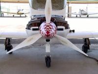
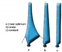

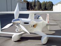
heres some math ive been reviewing.
Patrick, Fri Dec 12 2014, 12:29AM
im not sure what planform were needing in this application.
ive mentioned the elliptical prop before, not sure if thats worth pursuing in this application. but here are some pics.


heres some math ive been reviewing.

Re: Propeller Physics and VABs Program.
Ash Small, Fri Dec 12 2014, 12:36AM
We may want some taper, and I know I said I'd post some maths today, but submarines took up my free time. I'll try to post some maths tomorrow
(I hate maths as much as you do, Patrick
Ash Small, Fri Dec 12 2014, 12:36AM
We may want some taper, and I know I said I'd post some maths today, but submarines took up my free time. I'll try to post some maths tomorrow

(I hate maths as much as you do, Patrick

Re: Propeller Physics and VABs Program.
Patrick, Fri Dec 12 2014, 12:45AM
at 30" diameter and 3000rpm:
the tip is at: 143 m/s @ (15 inches)
the mid-span is: 60 m/s (@ 7.5 inches)
near hub is: 16 m/s (@ 2 inches)
Mach at tip then equals 143 / 340 m/s = 0.42M, so with reduced pressure hopefully no more than 0.6M
Patrick, Fri Dec 12 2014, 12:45AM
Ash Small wrote ...
(I hate maths as much as you do, Patrick
Yes, fluid flow is nothing more than cowardly trickery i say! (I hate maths as much as you do, Patrick

at 30" diameter and 3000rpm:
the tip is at: 143 m/s @ (15 inches)
the mid-span is: 60 m/s (@ 7.5 inches)
near hub is: 16 m/s (@ 2 inches)
Mach at tip then equals 143 / 340 m/s = 0.42M, so with reduced pressure hopefully no more than 0.6M
Re: Propeller Physics and VABs Program.
Ash Small, Fri Dec 12 2014, 12:52AM
Sometimes you just need to grab the maths demon firmly with both hands, and administer a swift kick to the groin area
Ash Small, Fri Dec 12 2014, 12:52AM
Patrick wrote ...
Ash Small wrote ...
(I hate maths as much as you do, Patrick
Yes, fluid flow is nothing more than cowardly trickery i say! (I hate maths as much as you do, Patrick

Sometimes you just need to grab the maths demon firmly with both hands, and administer a swift kick to the groin area

Re: Propeller Physics and VABs Program.
Patrick, Fri Dec 12 2014, 01:56AM
A kick to the huevos has now been issued.
 math with reguards to air density.
 trying to figure this out.

 im trying to figure out how he figures out the AOA of each crossetion. I dont know what a "slashed tip" is either.
Patrick, Fri Dec 12 2014, 01:56AM
A kick to the huevos has now been issued.
 math with reguards to air density.
 trying to figure this out.
 im trying to figure out how he figures out the AOA of each crossetion. I dont know what a "slashed tip" is either.
Re: Propeller Physics and VABs Program.
Ash Small, Fri Dec 12 2014, 02:25AM
'Parabolics' isn't just of relevance in the submarine thread, it's relevant here as well
I'll look at the links in the morning
Ash Small, Fri Dec 12 2014, 02:25AM
'Parabolics' isn't just of relevance in the submarine thread, it's relevant here as well

I'll look at the links in the morning
Re: Propeller Physics and VABs Program.
Patrick, Fri Dec 12 2014, 03:19AM
i continue with the math....

Z sub q is the circumferential velocity as the radius goes out.
im trying to figure out inhaled mass. And if under camber can be used.
Patrick, Fri Dec 12 2014, 03:19AM
i continue with the math....

Z sub q is the circumferential velocity as the radius goes out.
im trying to figure out inhaled mass. And if under camber can be used.
Re: Propeller Physics and VABs Program.
Andy, Fri Dec 12 2014, 09:15PM
 the pictures at the top, the topleft one, is the blade shape I would make the length based on rpm, and the angle is
Side not, the pancake motor is supposeable more eff not from the electrical side, but maybe from the angle that the magntic coils are further from the centre of the shaft, make the speed to torgue graphs more straight rather than ecillpe, or adjust more to the environment.
Andy, Fri Dec 12 2014, 09:15PM
And if under camber can be used.It can if you are design the blades as aerofoil rather than drag, and a tip to airspeed ratio of 3:1 is normal optimum for aerofoil, but the angle is realeted to drag at a certain airspeed, I think around still, with drag at 10% eff and aerofoil at 39-40% eff, you can replace the airspeed to meter/second of prop and times 3 to get the TSR, then decrease the angle of attack until the thing comes out of stall or a massive jump in thrust
 the pictures at the top, the topleft one, is the blade shape I would make the length based on rpm, and the angle is
Side not, the pancake motor is supposeable more eff not from the electrical side, but maybe from the angle that the magntic coils are further from the centre of the shaft, make the speed to torgue graphs more straight rather than ecillpe, or adjust more to the environment.
Re: Propeller Physics and VABs Program.
Ash Small, Fri Dec 12 2014, 11:46PM
I think we will end up with a NACA profile, with camber.
I'm just thinking through the 'tip speed', 'centripetal/centrifugal' thing. Working on 700feet/second tip velocity.
Overall mass of props has to be as low as possible, but strong enopugh to withstand centripetal/centrifugal forces.
I think we need to decide on CSA of prop before deciding on profile. Strength required to overcome centripetal/centrifugal forces with tip speed of 700 feet per second gives us a starting point.
Sorry about the slow response, feel like I've got pnumonia today.
Ash Small, Fri Dec 12 2014, 11:46PM
Patrick wrote ...
i continue with the math....

Z sub q is the circumferential velocity as the radius goes out.
im trying to figure out inhaled mass. And if under camber can be used.
i continue with the math....

Z sub q is the circumferential velocity as the radius goes out.
im trying to figure out inhaled mass. And if under camber can be used.
I think we will end up with a NACA profile, with camber.
I'm just thinking through the 'tip speed', 'centripetal/centrifugal' thing. Working on 700feet/second tip velocity.
Overall mass of props has to be as low as possible, but strong enopugh to withstand centripetal/centrifugal forces.
I think we need to decide on CSA of prop before deciding on profile. Strength required to overcome centripetal/centrifugal forces with tip speed of 700 feet per second gives us a starting point.
Sorry about the slow response, feel like I've got pnumonia today.
Re: Propeller Physics and VABs Program.
Patrick, Sat Dec 13 2014, 02:46AM
What's CSA ?
Patrick, Sat Dec 13 2014, 02:46AM
What's CSA ?
Re: Propeller Physics and VABs Program.
Ash Small, Sat Dec 13 2014, 03:42AM
Cross-Sectional Area. Surely we want to know this before we decide what shape it's going to be?
Ash Small, Sat Dec 13 2014, 03:42AM
Patrick wrote ...
What's CSA ?
What's CSA ?
Cross-Sectional Area. Surely we want to know this before we decide what shape it's going to be?

Re: Propeller Physics and VABs Program.
Ash Small, Sat Dec 13 2014, 02:51PM
I've just calculated that 700 feet per second is 213.36m/s.
This equates to 5235RPM for a 30" prop.
I'll work out disc loading later.
Ash Small, Sat Dec 13 2014, 02:51PM
I've just calculated that 700 feet per second is 213.36m/s.
This equates to 5235RPM for a 30" prop.
I'll work out disc loading later.
Re: Propeller Physics and VABs Program.
Ash Small, Sat Dec 13 2014, 06:25PM
Each prop has 0.456m^2 disc area. For 10kg all up weight, load per prop is 2.5kg.
This equates to 5.48kg/m^2 disc loading, which is higher than I was hoping for, but this also depends on how much of the total mass is batteries.
Next thing, I think, is to consider the propertires of the CF. Ultimate tensile strength and bending strength should give us a CSA. I'm thinking some taper towards the tip would probably be ok, although we do need to consider the bending stresses.
I'll have to look up some figures.
I'm assuming around 2000rpm for hover, and max rpm of 5k, or somewhere close to this. Maybe we could push the hover to 3k?
Re: Propeller Physics and VABs Program.
Patrick, Sun Dec 14 2014, 07:30AM
i was thinking 2k would be more effcient than 3k rpm, right? as we want to accelerate the most air by the least amount. or can a higher RPM still do this?
this is useful, it shows a great crabon layup with tension carying the force in a way i never would have thought of.
Re: Propeller Physics and VABs Program.
Ash Small, Sun Dec 14 2014, 02:45PM
I think it comes down to maximum rate of ascent. If max rpm is 5k, and we want twice hover thrust, we set hover thrust for 2.5k.
If we set hover thrust for 2k, then at 5k it's producing 2.5 times hover thrust, so needs to be stronger, so therefore has more drag.
If we set hover thrust for 3k, then at 5k it's only producing 1.66 times hover thrust, so less drag.
Obviously, as rate of ascent increases, thrust decreases, but I don't think that will be a big issue here. We just need a starting point to lay up a prop for some static tests.
We do need to get some figures for tensile strength, etc., then we'll need a safety factor. I'm also just assuming max tip speed of ~200m/s based on full size copter design using CF, but the tensile strength figures should be useful here.
It could just be that the tip speed used on full size copters is 200m/s to prevent the tips from going supersonic, I've not done the maths, but I assume 200m/s is a good point to start.
Re: Propeller Physics and VABs Program.
Dr. Slack, Sun Dec 14 2014, 06:31PM
at 5k it's producing 6.25 times the 2k thrust
Dr. Slack, Sun Dec 14 2014, 06:31PM
at 5k it's producing 6.25 times the 2k thrust
Re: Propeller Physics and VABs Program.
Ash Small, Sun Dec 14 2014, 07:10PM
Thanks Neil. Where do you get your figures from? Any cjhance of a link?
I was rather hoping you or Uspring or someone would get involved at this point
It sounds, from what you're saying that we may want to set the hover at around 4k rpm.
Ash Small, Sun Dec 14 2014, 07:10PM
Dr. Slack wrote ...
at 5k it's producing 6.25 times the 2k thrust
at 5k it's producing 6.25 times the 2k thrust
Thanks Neil. Where do you get your figures from? Any cjhance of a link?
I was rather hoping you or Uspring or someone would get involved at this point

It sounds, from what you're saying that we may want to set the hover at around 4k rpm.
Re: Propeller Physics and VABs Program.
Patrick, Mon Dec 15 2014, 12:09AM
if we double the speed we get 4 times the lift right? just like a forward wing...
Patrick, Mon Dec 15 2014, 12:09AM
if we double the speed we get 4 times the lift right? just like a forward wing...
Re: Propeller Physics and VABs Program.
Ash Small, Mon Dec 15 2014, 12:16AM
I've not checked the maths yet. I know about picking the right pitch for HP and RPM. I'm hoping for a bit of input from others, but I can look it up if necessary.
Ash Small, Mon Dec 15 2014, 12:16AM
Patrick wrote ...
if we double the speed we get 4 times the lift right? just like a forward wing...
if we double the speed we get 4 times the lift right? just like a forward wing...
I've not checked the maths yet. I know about picking the right pitch for HP and RPM. I'm hoping for a bit of input from others, but I can look it up if necessary.
Re: Propeller Physics and VABs Program.
Patrick, Mon Dec 15 2014, 12:48AM
i guess we need to know the slip to figure on pitch, right?
Patrick, Mon Dec 15 2014, 12:48AM
i guess we need to know the slip to figure on pitch, right?
Re: Propeller Physics and VABs Program.
Ash Small, Mon Dec 15 2014, 01:35AM

Ash Small, Mon Dec 15 2014, 01:35AM
Patrick wrote ...
i guess we need to know the slip to figure on pitch, right?
We certainly need to check that we're using the 'right maths' i guess we need to know the slip to figure on pitch, right?

Re: Propeller Physics and VABs Program.
Ash Small, Mon Dec 15 2014, 02:28PM
Well, I've done some more googling this morning, and ascertained that most 'copters have a blade angle of around 5 degrees when hovering.
I've found various other equations, etc., but none that seem to be appropriate here,
Supersonic speed is 320m/s, so the 200m/s figure assumed above is well within that, although the propeller shape does cause some air to move faster than this, so 200m/s is probably a sensible limit.
A 5 degree angle of attack is much less than any of the other prop designs posted thus far, and will have a lot less drag.
I still need to google a bit more maths.
EDIT: I've discovered that a typical cambered airfoil wath a 5 degree angle of attack has a lift coefficient of 1.
Found something with chord length, seem to be getting somewhere. Pretty busy tomorrow, though.
Re: Propeller Physics and VABs Program.
Patrick, Mon Dec 15 2014, 11:05PM
with the 5 degree remark, does that mean a helix of 5 degrees?
Patrick, Mon Dec 15 2014, 11:05PM
with the 5 degree remark, does that mean a helix of 5 degrees?
Re: Propeller Physics and VABs Program.
Ash Small, Tue Dec 16 2014, 12:21AM
I'm not sure yet. I think it's blade angle, in fact, I'm pretty sure it is.
I'm assuming we tune everything be varying chord length, but I'm still reading.
Maybe a day or two yet.
Ash Small, Tue Dec 16 2014, 12:21AM
Patrick wrote ...
with the 5 degree remark, does that mean a helix of 5 degrees?
with the 5 degree remark, does that mean a helix of 5 degrees?
I'm not sure yet. I think it's blade angle, in fact, I'm pretty sure it is.
I'm assuming we tune everything be varying chord length, but I'm still reading.
Maybe a day or two yet.
Re: Propeller Physics and VABs Program.
Patrick, Tue Dec 16 2014, 01:05AM
From APC company . . .
12 x 4.5 inch prop, made specifically for multirotors. shows the planned cross cuts.
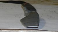
chopped at 5 inch radius.
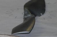
chopped at 4 inch radius.

overview at 3 inch radius.
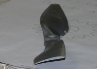
chopped at 3 inch radius.
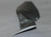
chopped at 2 inch radius.

1 inch overview.

chopped at 1 inch radius.
Patrick, Tue Dec 16 2014, 01:05AM
From APC company . . .
AirfoilsThe airfoils may have arbitrary shapes defined with either tabular data (splined cubic fits) or analytical functions typically used for NACA airfoils. The airfoil shapes may vary with span. Capability exists to smoothly "splice" together widely different airfoil shapes. The dominant basis for the primary airfoil shape used in most APC propellers is similar to the NACA 4412 and Clark-Y airfoils, except the leading edge is somewhat lower. Also, the aft region is somewhat thicker. This alters the zero-lift angle by approximately one degree and provides greater lift without having to twist the blade even more. All blades have some washout near the tip. For applications where Mach number effects become significant near the tip, either pitch washout or camber reduction tailoring minimizes Mach drag rise.

12 x 4.5 inch prop, made specifically for multirotors. shows the planned cross cuts.

chopped at 5 inch radius.

chopped at 4 inch radius.

overview at 3 inch radius.

chopped at 3 inch radius.

chopped at 2 inch radius.

1 inch overview.

chopped at 1 inch radius.
Re: Propeller Physics and VABs Program.
Andy, Tue Dec 16 2014, 04:29AM


Andy, Tue Dec 16 2014, 04:29AM
The airfoils may have arbitrary shapes defined with either tabular data (splined cubic fits) or analytical functions typically used for NACA airfoils. The airfoil shapes may vary with span. Capability exists to smoothly "splice" together widely different airfoil shapes. The dominant basis for the primary airfoil shape used in most APC propellers is similar to the NACA 4412 and Clark-Y airfoils, except the leading edge is somewhat lower. Also, the aft region is somewhat thicker. This alters the zero-lift angle by approximately one degree and provides greater lift without having to twist the blade even more. All blades have some washout near the tip. For applications where Mach number effects become significant near the tip, either pitch washout or camber reduction tailoring minimizes Mach drag rise.Flaps on plane wings


Re: Propeller Physics and VABs Program.
Patrick, Tue Dec 16 2014, 05:15AM
 12 x 4.5 MR prop data sheet. (i had to use the wayback machine)
From the above:
3,000 rpm, thrust becomes zero at 21 mph.
4,000 rpm, thrust becomes zero at 27.6 mph
5,000 rpm, thrust becomes zero at 34.5 mph
im not sure what all the terms mean like "J" and all.
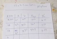
Personal test of this prop. i realy need to know the flow speed in a hover, thats the part thats holding me back.
EDIT: now im starting to see a solution, or at least a path to one. the datasheets show a max thrust at zero speed, so clearly the measurements in each RPM "bunch" are true static thrust. so with static thrust we could pull tree stumps out. most propellers are never rated in this way, or kinda iffy at best.
EDIT: i think its 17 or so mph that i should aim for.
Patrick, Tue Dec 16 2014, 05:15AM
Andy wrote ...


yes, but there under camber is even done differently, they have noticeably more camber at the 0.25 trailing edge chord. thats unusual and a departure from there fixed wing props. you can see it in the 2 and 3 inch radius pics.The airfoils may have arbitrary shapes defined with either tabular data (splined cubic fits) or analytical functions typically used for NACA airfoils. The airfoil shapes may vary with span. Capability exists to smoothly "splice" together widely different airfoil shapes. The dominant basis for the primary airfoil shape used in most APC propellers is similar to the NACA 4412 and Clark-Y airfoils, except the leading edge is somewhat lower. Also, the aft region is somewhat thicker. This alters the zero-lift angle by approximately one degree and provides greater lift without having to twist the blade even more. All blades have some washout near the tip. For applications where Mach number effects become significant near the tip, either pitch washout or camber reduction tailoring minimizes Mach drag rise.Flaps on plane wings


 12 x 4.5 MR prop data sheet. (i had to use the wayback machine)
From the above:
3,000 rpm, thrust becomes zero at 21 mph.
4,000 rpm, thrust becomes zero at 27.6 mph
5,000 rpm, thrust becomes zero at 34.5 mph
im not sure what all the terms mean like "J" and all.

Personal test of this prop. i realy need to know the flow speed in a hover, thats the part thats holding me back.
EDIT: now im starting to see a solution, or at least a path to one. the datasheets show a max thrust at zero speed, so clearly the measurements in each RPM "bunch" are true static thrust. so with static thrust we could pull tree stumps out. most propellers are never rated in this way, or kinda iffy at best.
EDIT: i think its 17 or so mph that i should aim for.
Re: Propeller Physics and VABs Program.
Ash Small, Tue Dec 16 2014, 01:47PM
The way I see it, it'#s the static thrust we're interested in for hover.
We should design for greatest efficiency at hover, but allow for higher RPM for ascent, etc. I'm assuming twice the static thrust will be plenty at max RPM, but we can confirm this once we have the 'right maths'.
Grom what I've read on prop design, those you've linked to with thicker aft sections than standard NACA profile don't achieve laminar flow over the trailing edge, leading to turbulence losses. Do we have figures for disc loading for those props? Our current plan has around 5kg/m^2 disc loading, and, as I previously mentioned, those you linked to are, I think, for much higher loadings.
I have found some useful maths and NACA profile design tools, but I still need to read a bit more. I assume we need to consider 'section lift coefficients' and stuff like that, which, I think, requires integration, or some such clever mysticism, which I'll also have to brush up on. I also found something on thin section airfoils which looked useful.
I suspect we may need some form of spreadsheet for designing a NACA profile specifically for our purposes.
When we get the sections, I'm sure I can put them into a 3D CAD package and get dxf files out, or whatever you need for the 3D printer.
EDIT: Found this regarding laminar flow NACA profiles: "Laminar flow airfoils were originally developed for the purpose of making an airplane fly faster. The laminar flow wing is usually thinner than the conventional airfoil, the leading edge is more pointed and its upper and lower surfaces are nearly symmetrical. The major and most important difference between the two types of airfoil is this, the thickest part of a laminar wing occurs at 50% chord while in the conventional design the thickest part is at 25% chord.
The effect achieved by this type of design of a wing is to maintain the laminar flow of air throughout a greater percentage of the chord of the wing and to control the transition point. Drag is therefore considerably reduced since the laminar airfoil takes less energy to slide through the air. The pressure distribution on the laminar flow wing is much more even since the camber of the wing from the leading edge to the point of maximum camber is more gradual than on the conventional airfoil. However, at the point of stall, the transition point moves more rapidly forward."

EDIT: Also found this:
And this is really interesting.
I still need to read a bit more on this.
EDIT: This, on the naca 0012 profile is pretty interesting too, especially at low angles of attack, but I think the maximum thickness should be further back, at 50% chord length, from the other stuff I've read.
Edit: I'm thinking something like a naca 16009 or 16006 profile, or something similar.
Ash Small, Tue Dec 16 2014, 01:47PM
The way I see it, it'#s the static thrust we're interested in for hover.
We should design for greatest efficiency at hover, but allow for higher RPM for ascent, etc. I'm assuming twice the static thrust will be plenty at max RPM, but we can confirm this once we have the 'right maths'.
Grom what I've read on prop design, those you've linked to with thicker aft sections than standard NACA profile don't achieve laminar flow over the trailing edge, leading to turbulence losses. Do we have figures for disc loading for those props? Our current plan has around 5kg/m^2 disc loading, and, as I previously mentioned, those you linked to are, I think, for much higher loadings.
I have found some useful maths and NACA profile design tools, but I still need to read a bit more. I assume we need to consider 'section lift coefficients' and stuff like that, which, I think, requires integration, or some such clever mysticism, which I'll also have to brush up on. I also found something on thin section airfoils which looked useful.
I suspect we may need some form of spreadsheet for designing a NACA profile specifically for our purposes.
When we get the sections, I'm sure I can put them into a 3D CAD package and get dxf files out, or whatever you need for the 3D printer.
EDIT: Found this regarding laminar flow NACA profiles: "Laminar flow airfoils were originally developed for the purpose of making an airplane fly faster. The laminar flow wing is usually thinner than the conventional airfoil, the leading edge is more pointed and its upper and lower surfaces are nearly symmetrical. The major and most important difference between the two types of airfoil is this, the thickest part of a laminar wing occurs at 50% chord while in the conventional design the thickest part is at 25% chord.
The effect achieved by this type of design of a wing is to maintain the laminar flow of air throughout a greater percentage of the chord of the wing and to control the transition point. Drag is therefore considerably reduced since the laminar airfoil takes less energy to slide through the air. The pressure distribution on the laminar flow wing is much more even since the camber of the wing from the leading edge to the point of maximum camber is more gradual than on the conventional airfoil. However, at the point of stall, the transition point moves more rapidly forward."

EDIT: Also found this:

And this is really interesting.

I still need to read a bit more on this.
EDIT: This, on the naca 0012 profile is pretty interesting too, especially at low angles of attack, but I think the maximum thickness should be further back, at 50% chord length, from the other stuff I've read.
Edit: I'm thinking something like a naca 16009 or 16006 profile, or something similar.
Re: Propeller Physics and VABs Program.
Ash Small, Wed Dec 17 2014, 02:37PM
The main question seems to be cambered blades or laminar flow.
Most copters use laminar flow, as far as I'm aware. If we can achieve laminar flow with fixed blades then this is the best solution, I think, otherwise we'd probably be better off with camber.
Ideally, we want the 'drag bucket' to begin at hover and continue up to max RPM.
There are plenty of examples of laminar flow NACA profiles with drag buckets from Mach 0.5 to Mach 0.7, which equates to 1,600m/s to 2240m/s. The max RPM we were working with, 2000m/s equates to Mach 0.625.
I still think this satisfies all our requirements, lift to drag ratio, low Reynolds number, lightweight blades, low disc loading, etc.
In order to achieve this it will require a bit more maths, though
Edit: Mach 0.5 equates to hover at 4000 RPM. Max RPM will be between 5000 and 5500 RPM. Does this give us sufficient ascent rate, manouverability, etc?....More maths required.
Ash Small, Wed Dec 17 2014, 02:37PM
The main question seems to be cambered blades or laminar flow.
Most copters use laminar flow, as far as I'm aware. If we can achieve laminar flow with fixed blades then this is the best solution, I think, otherwise we'd probably be better off with camber.
Ideally, we want the 'drag bucket' to begin at hover and continue up to max RPM.
There are plenty of examples of laminar flow NACA profiles with drag buckets from Mach 0.5 to Mach 0.7, which equates to 1,600m/s to 2240m/s. The max RPM we were working with, 2000m/s equates to Mach 0.625.
I still think this satisfies all our requirements, lift to drag ratio, low Reynolds number, lightweight blades, low disc loading, etc.
In order to achieve this it will require a bit more maths, though

Edit: Mach 0.5 equates to hover at 4000 RPM. Max RPM will be between 5000 and 5500 RPM. Does this give us sufficient ascent rate, manouverability, etc?....More maths required.
Re: Propeller Physics and VABs Program.
Ash Small, Wed Dec 17 2014, 08:42PM
Found a downloadable program called XFOIL for designing subsonic airfoils
Not tried it yet, but it looks like it could be very useful. It runs on 32 bit architecture.
EDIT: Also discovered we don't want max thickness at 50% chord length at the tips. I suspect we may want to move max thickness forwards towards the centre of the rotor, but it looks like it's what we want towards the outside of the rotor.
We also want as thin a section as possible, to give sufficient strength, and as much chord length and angle of attact to give sufficient lift for hover at 4000RPM (assuming we stick with the figures above).
Looks like I need to re-read thin airfoil theory and section lift coefficient.
Almost ready to input some numbers, I think.
Ash Small, Wed Dec 17 2014, 08:42PM
Found a downloadable program called XFOIL for designing subsonic airfoils

Not tried it yet, but it looks like it could be very useful. It runs on 32 bit architecture.
EDIT: Also discovered we don't want max thickness at 50% chord length at the tips. I suspect we may want to move max thickness forwards towards the centre of the rotor, but it looks like it's what we want towards the outside of the rotor.
We also want as thin a section as possible, to give sufficient strength, and as much chord length and angle of attact to give sufficient lift for hover at 4000RPM (assuming we stick with the figures above).
Looks like I need to re-read thin airfoil theory and section lift coefficient.
Almost ready to input some numbers, I think.
Re: Propeller Physics and VABs Program.
Patrick, Thu Dec 18 2014, 01:39AM
tomarrow is my last class for this semster, so then ill be full time on props. i really need to make progress.
jve got the 3D printer really tuned good. So ill start making molds as soon as we have something useful. ive aslo got a BC3538/10 motor rewound so well see on my new dynomometer a slower motor with larger prop, compared to the previous high speed configurations.
Re: Propeller Physics and VABs Program.
Ash Small, Thu Dec 18 2014, 02:53AM
Ash Small, Thu Dec 18 2014, 02:53AM
Patrick wrote ...
tomarrow is my last class for this semster, so then ill be full time on props. i really need to make progress.
jve got the 3D printer really tuned good. So ill start making molds as soon as we have something useful. ive aslo got a BC3538/10 motor rewound so well see on my new dynomometer a slower motor with larger prop, compared to the previous high speed configurations.
I think we either need a motor that goes to 5k or a belt drive that takes it to 5k.
Re: Propeller Physics and VABs Program.
Patrick, Thu Dec 18 2014, 09:05AM
i can get a prop to 5k rpm. (been working on it the past week )
)
Patrick, Thu Dec 18 2014, 09:05AM
i can get a prop to 5k rpm. (been working on it the past week
 )
)Re: Propeller Physics and VABs Program.
Patrick, Fri Dec 19 2014, 09:45PM
with regards to disc loading, should i just divide mass into area ?
Patrick, Fri Dec 19 2014, 09:45PM
with regards to disc loading, should i just divide mass into area ?
Re: Propeller Physics and VABs Program.
Ash Small, Fri Dec 19 2014, 11:01PM
Yes, but it's per prop. You divide mass by number of props first, or you get the wrong result.
There are a few points I need to mention. I think we can DESIGN a prop that will have laminar flow from Mach 0.5 to ~Mach 0.7, but if we can't manufacture it accurately enough it won't work.
We've reached the point (30" props) where Mach 0.5 = 4k RPM. If we go bigger, disc loading decreases and RPM decrease.
I think the starting point is a modified NACA 0012 profile.
Ash Small, Fri Dec 19 2014, 11:01PM
Patrick wrote ...
with regards to disc loading, should i just divide mass into area ?
with regards to disc loading, should i just divide mass into area ?
Yes, but it's per prop. You divide mass by number of props first, or you get the wrong result.
There are a few points I need to mention. I think we can DESIGN a prop that will have laminar flow from Mach 0.5 to ~Mach 0.7, but if we can't manufacture it accurately enough it won't work.
We've reached the point (30" props) where Mach 0.5 = 4k RPM. If we go bigger, disc loading decreases and RPM decrease.
I think the starting point is a modified NACA 0012 profile.
Re: Propeller Physics and VABs Program.
Patrick, Sat Dec 20 2014, 01:28AM
ok let me look at the prop "makability" since im out of classes for a month.
theres also this comment im studying:

From the red statement, I thinking that this describes F=ma, and KE = (1/2)m *V^2
(the 4S means 14.8 volts, LiPo)
(the 6S means 22.2 volts, LiPo)
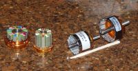
The short fat one really gave up the smoke in class, while demonstrating...very embarrassing.

Here you can see ive colorized the stator for rewinding, and recoated with epoxy. ill rewind from 10 turns to 16 turns. the small one ill explain later. its the BC3530/10 thats important.
As for the propeller article, im totally perplexed by the following:
EDIT: Got a few hours in and solved at least some of these problems.

Not being able to make head way with pitch, slip, and the tangent of a helix I went to the great all know wiki. bailing me out of trouble once again.
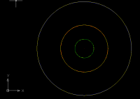
here are the measruements id like to reverse "math-matify" from the ellipse article. 6", 15" and 30" radius for a manned 72" standard prop.
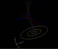
Green is 6" , red 15" and blue is 30" radii, pink is center.
Nearly perfect matches for the article.
47 turns of the prop, traveling at 3516 inches per/second. I reduced this to 74.8 inches long, one revolution.
I still don't know the math, but at least I know whats being described.
EDIT 2 :
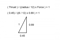
I still don't see where these numbers come from. 0.45 and 0.89. (I should mention the hypotenuse is always 1)
EDIT: im very tired, but I thinkin the above triangle the degree with hyptonese and 90 degree corner solves for those two sides.
If I can solve this triangle, then it can be applied as an integral from root to tip.
Patrick, Sat Dec 20 2014, 01:28AM
ok let me look at the prop "makability" since im out of classes for a month.
theres also this comment im studying:

RCgroups "scirocco" says:From the green statement, I think we see the Electronic Speed Control, and motor acting as if it were an SMPS.
if you focus on weight and Kv, you will get into the ballpark and it will also allow you to compare motors regardless of labelling and vendor.
Building on Doug's comments above, weight straight away is a pretty valid indicator of power handling, again independent of inflated vendor claims. You can exploit weight in a number of ways. First off, if you know your power requirement, it tells you you should be looking at motors of at least a certain weight. Or if you have a tail heavy model you may choose to use a bigger motor than strictly necessary for power handling, noting that electric motors are a lot lighter than their glow cousins, where it counts the most right up front. Or if you've got a specialised requirement such as a 30 sec motor run in a glider, you might be willing to push a small motor hard, accepting lower efficiency for weight savings.
Max current rating is important, but don't be afraid to discount it if it is giving you unrealistically high power levels based on motor weight.
Then Kv. First off, don't think of Kv as a rating, which implies a figure of merit. It is a characteristic, a bit like colour. Red is not more colour than green, just different. Similarly low or high Kv is not better or worse, it's just a characteristic you choose to suit your application.
Kv HAS to be considered together with voltage and IMO is NOT analagous to high and low gear ratios for that reason.
Looking at your statement "a lower KV rating could be used with a higher diameter/pitch prop to produce more torque / climbing power,". More accurately, at the same voltage, a lower Kv motor of the same size as a higher Kv motor will use a larger diameter prop to at lower rpm to achieve the same power. While it is true that at the same current the lower Kv motor will have higher torque (torque is proportional to the inverse of Kv x current), both the low Kv and high Kv motor at the same current will have the same power (torque x rpm), remembering this is a same voltage comparison. If you only need to fly slowly, the slower turning big prop will be a better solution as the larger diameter prop will be a bit more efficient, but the tradeoff is top speed will be limited.
If we take out the common voltage, then your statement is no longer valid. For motors of the same size, 6S and Kv=400 and 4S and Kv=600 will run the same size props and require about the same power - just at higher current for the 4S.
Ron is very generous to quote an older post - there is an expanded discussion on motor selection methodology in my blog that might help some.
Keep the good questions coming
From the red statement, I thinking that this describes F=ma, and KE = (1/2)m *V^2
(the 4S means 14.8 volts, LiPo)
(the 6S means 22.2 volts, LiPo)

The short fat one really gave up the smoke in class, while demonstrating...very embarrassing.

Here you can see ive colorized the stator for rewinding, and recoated with epoxy. ill rewind from 10 turns to 16 turns. the small one ill explain later. its the BC3530/10 thats important.
As for the propeller article, im totally perplexed by the following:
Now it is necessary to determine the blade angle versus the radius, the helical path each portion of the blade follows as it passes through the air. Without consideration of the AOA, the tangent of the helical path at any radius is obtained by dividing the design forward speed by the rotational velocity at that radius. For a plane with a design speed of 200 mph, we multiply by 22/15 to get the speed in feet/second. To get the rotational velocity at a given radius, we multiply the radius, in inches, by 2 x π x rpm/60 x radius/12. With the engine operated at its rated 2800 rpm, we would obtain 63.4 degrees at 6-inch radius, 36.9 degrees at 15-inch, and 21.8 degrees at 30-inch.I have no idea how these magical angles were calculated. i may have to brute force the math with AutoCAD.
EDIT: Got a few hours in and solved at least some of these problems.

Not being able to make head way with pitch, slip, and the tangent of a helix I went to the great all know wiki. bailing me out of trouble once again.

here are the measruements id like to reverse "math-matify" from the ellipse article. 6", 15" and 30" radius for a manned 72" standard prop.

Green is 6" , red 15" and blue is 30" radii, pink is center.

Nearly perfect matches for the article.

47 turns of the prop, traveling at 3516 inches per/second. I reduced this to 74.8 inches long, one revolution.
I still don't know the math, but at least I know whats being described.
EDIT 2 :

I still don't see where these numbers come from. 0.45 and 0.89. (I should mention the hypotenuse is always 1)
EDIT: im very tired, but I thinkin the above triangle the degree with hyptonese and 90 degree corner solves for those two sides.
If I can solve this triangle, then it can be applied as an integral from root to tip.
Re: Propeller Physics and VABs Program.
Ash Small, Sat Dec 20 2014, 12:26PM
Had a quick look through, and I agree that the motor itself has to be considered last.
Also, the 'propeller theory' bit. All the maths I've done so far is for hover mode. That article mentions a plane with a top speed of 200MPH. While we do need to do some maths at max rpm, I think we need to concentrate on hover at Mach 0.5.
There are fundamental differences between how the 'RC' crowd look at this, and how NASA and the helicopter designers look at it.
Looking at it from 'disc loading' and 'Mach number' is not really anything like 'diameter' and 'rpm'.
We have the choice of using 'RC' maths, or 'NASA' maths.
(The RC maths is based on figures originally published by the prop manufacturers to make it easy for their customers to get an approximate figure)
EDIT: My current understanding is that we want Mach 0.5 tip speed at hover, and that any part of the blade that travels faster than Mach 0.5 at max RPM (when tip speed is ~Mach 0.625-0.7) wants it's max thickness pushed back towards 50% chord length.
Angle of attack is calculated using the relevant Mach number at hover. (o.5 for tip, less for rest of blade)
Do you understand the 'drag bucket' theory?
It comes down to Mach numbers and lift/drag ratios. (I think the 'submarine thread' comes down to something very similar as well )
)
(I was looking at NACA profiles the other day, and all of a sudden, it just leaped off the page at me, and fell into place.)
The only real difference between this and a real copter is we have fixed blades, so we design the blade for hover at Mach 0.5 tipspeed. This is fixed by our design. We then design for a drag bucket from Mach 0.5 up to as close to Mach 0.7 as we can get, just like NASA does. Everything else is already fixed.
Once you understand the relevance of the Mach numbers, everything else just falls into place. This is where the max tip speed of ~70 feet per second comes from, the top of the drag bucket, and hover has to be at the bottom of the drag bucket. The whole 'operating region' has to be inside the drag bucket, or, to put it another way, the drag bucket IS the operating region.
Lift to drag ratio is already defined by these parameters (from thin airfoil theory).
The only thing we need to adjust is the NACA profile at different blade sections.
Ash Small, Sat Dec 20 2014, 12:26PM
Had a quick look through, and I agree that the motor itself has to be considered last.
Also, the 'propeller theory' bit. All the maths I've done so far is for hover mode. That article mentions a plane with a top speed of 200MPH. While we do need to do some maths at max rpm, I think we need to concentrate on hover at Mach 0.5.
There are fundamental differences between how the 'RC' crowd look at this, and how NASA and the helicopter designers look at it.
Looking at it from 'disc loading' and 'Mach number' is not really anything like 'diameter' and 'rpm'.
We have the choice of using 'RC' maths, or 'NASA' maths.
(The RC maths is based on figures originally published by the prop manufacturers to make it easy for their customers to get an approximate figure)
EDIT: My current understanding is that we want Mach 0.5 tip speed at hover, and that any part of the blade that travels faster than Mach 0.5 at max RPM (when tip speed is ~Mach 0.625-0.7) wants it's max thickness pushed back towards 50% chord length.
Angle of attack is calculated using the relevant Mach number at hover. (o.5 for tip, less for rest of blade)
Do you understand the 'drag bucket' theory?
It comes down to Mach numbers and lift/drag ratios. (I think the 'submarine thread' comes down to something very similar as well
 )
)(I was looking at NACA profiles the other day, and all of a sudden, it just leaped off the page at me, and fell into place.)
The only real difference between this and a real copter is we have fixed blades, so we design the blade for hover at Mach 0.5 tipspeed. This is fixed by our design. We then design for a drag bucket from Mach 0.5 up to as close to Mach 0.7 as we can get, just like NASA does. Everything else is already fixed.
Once you understand the relevance of the Mach numbers, everything else just falls into place. This is where the max tip speed of ~70 feet per second comes from, the top of the drag bucket, and hover has to be at the bottom of the drag bucket. The whole 'operating region' has to be inside the drag bucket, or, to put it another way, the drag bucket IS the operating region.
Lift to drag ratio is already defined by these parameters (from thin airfoil theory).
The only thing we need to adjust is the NACA profile at different blade sections.
Re: Propeller Physics and VABs Program.
Patrick, Sun Dec 21 2014, 02:30AM
ok, we'll put the ellipse propeller on hold. the purpose of that research was to see if it would scale to our size and if more airmass could be inducted at the root, thus decreases the overall diameter, without loosing the advantage of the larger diameters.
be that as it may. ill try to 3D print a root-hub mold section to tight tolerances of the NACA 0012. ill twist it i guess to that similar to the APC prop. Ill initially start with the pitch at 5.5 inches. all the props at 14" or larger that i find tend to be 5, 5.5, 8 or 9" in pitch.
Im also rewinding the previous motors to test a 1400kv and 800kv configuration turning the same 14x5.5 multirotor prop. both at 11.1 volts.

NACA 16009 profile

NACA 0010 profile

NACA 4308 profile. Id like to verify this one with the mold.
we can only get the full drag bucket in the first quadrant with unsymetric airfoils right? the under camber does that.
Patrick, Sun Dec 21 2014, 02:30AM
ok, we'll put the ellipse propeller on hold. the purpose of that research was to see if it would scale to our size and if more airmass could be inducted at the root, thus decreases the overall diameter, without loosing the advantage of the larger diameters.
be that as it may. ill try to 3D print a root-hub mold section to tight tolerances of the NACA 0012. ill twist it i guess to that similar to the APC prop. Ill initially start with the pitch at 5.5 inches. all the props at 14" or larger that i find tend to be 5, 5.5, 8 or 9" in pitch.
Im also rewinding the previous motors to test a 1400kv and 800kv configuration turning the same 14x5.5 multirotor prop. both at 11.1 volts.

NACA 16009 profile

NACA 0010 profile

NACA 4308 profile. Id like to verify this one with the mold.
we can only get the full drag bucket in the first quadrant with unsymetric airfoils right? the under camber does that.
Re: Propeller Physics and VABs Program.
Ash Small, Sun Dec 21 2014, 10:20AM
If we need 25N thrust at 4k rpm (Mach 0.5), we need to calculate angle of attack and chord length, I think.
I need to read a bit more. I saw a calculator that analyzed for different Mach numbers and, I think, did drag bucket calculations.
We'll get the lift with a very low angle at Mach 0.5. This results in very low drag.
I've not yet started the pitch or chord length calculations. Hopefully I'll get a chance to look at this again later.
EDIT: I think we just calculate the chord length and pitch for each blade section that gives the lift we require with minimum drag, and we have the optimum design,
I do need to have another look at the detail, though.
Blade section comes into play here too, we need enough CF to give the strength we need, but no more. If we put all these figures in we'll get an optimum design out.
Mach 0.5 to Mach 0.7 is apparently the optimum range, from what I read, but I'll re-read and post links.
I think this is where most of the info came from: But I did find something where you vary the Mach number.
EDIT: Just reading this at the moment:
]ada393685.pdf[/file]
Just trying to get a 'feel' for this stuff
Well, it says this
"For a fixed airfoil shape and a fixed Mach
number, the lift is almost a linear function of the angle of attack"
I suppose I'm going to have to download XFOIL and try to get it to run.......I'll do a bit more background reading first, though.
Well, I've read the XFOIL user notes nere: and I think it' sounds fairly straightforward, we input the data and it predicts the drag
Ash Small, Sun Dec 21 2014, 10:20AM
If we need 25N thrust at 4k rpm (Mach 0.5), we need to calculate angle of attack and chord length, I think.
I need to read a bit more. I saw a calculator that analyzed for different Mach numbers and, I think, did drag bucket calculations.
We'll get the lift with a very low angle at Mach 0.5. This results in very low drag.
I've not yet started the pitch or chord length calculations. Hopefully I'll get a chance to look at this again later.
EDIT: I think we just calculate the chord length and pitch for each blade section that gives the lift we require with minimum drag, and we have the optimum design,
I do need to have another look at the detail, though.
Blade section comes into play here too, we need enough CF to give the strength we need, but no more. If we put all these figures in we'll get an optimum design out.
Mach 0.5 to Mach 0.7 is apparently the optimum range, from what I read, but I'll re-read and post links.
I think this is where most of the info came from:
 But I did find something where you vary the Mach number.
EDIT: Just reading this at the moment:
]ada393685.pdf[/file]
Just trying to get a 'feel' for this stuff

Well, it says this
"For a fixed airfoil shape and a fixed Mach
number, the lift is almost a linear function of the angle of attack"
I suppose I'm going to have to download XFOIL and try to get it to run.......I'll do a bit more background reading first, though.
Well, I've read the XFOIL user notes nere:
 and I think it' sounds fairly straightforward, we input the data and it predicts the drag
Re: Propeller Physics and VABs Program.
Patrick, Sun Dec 21 2014, 10:04PM
i dont know how to run or if i can run unix.
Patrick, Sun Dec 21 2014, 10:04PM
i dont know how to run or if i can run unix.
Re: Propeller Physics and VABs Program.
Ash Small, Sun Dec 21 2014, 10:21PM
This will take a bit of sorting. I think there is a version that doesn't need UNIX, but doesn't have the 'Windows interface' (sic)
UNIX is basically LINUX, sort of, except LINUX is free.
I do think XFOIL is worth looking into.
Ash Small, Sun Dec 21 2014, 10:21PM
Patrick wrote ...
i dont know how to run or if i can run unix.
i dont know how to run or if i can run unix.
This will take a bit of sorting. I think there is a version that doesn't need UNIX, but doesn't have the 'Windows interface' (sic)
UNIX is basically LINUX, sort of, except LINUX is free.
I do think XFOIL is worth looking into.
Re: Propeller Physics and VABs Program.
Andy, Tue Dec 23 2014, 03:52AM
Hi Patrick, can give you a picture of a setup, that can be used to workout the props, but don't know if I should spend the effort, do you want a third opinion?
Andy, Tue Dec 23 2014, 03:52AM
Hi Patrick, can give you a picture of a setup, that can be used to workout the props, but don't know if I should spend the effort, do you want a third opinion?
Re: Propeller Physics and VABs Program.
Patrick, Tue Dec 23 2014, 08:29AM
do you want the machine diamgram? or the dyno setup?
and yes another opinions are welcome.
Patrick, Tue Dec 23 2014, 08:29AM
Andy wrote ...
Hi Patrick, can give you a picture of a setup, that can be used to workout the props, but don't know if I should spend the effort, do you want a third opinion?
Hi Patrick, can give you a picture of a setup, that can be used to workout the props, but don't know if I should spend the effort, do you want a third opinion?
do you want the machine diamgram? or the dyno setup?
and yes another opinions are welcome.
Re: Propeller Physics and VABs Program.
Ash Small, Tue Dec 23 2014, 10:09AM
Ok, just to re-count where I am with this, assuming a drag bucket from Mach 0.5 to Mach 0.7 tip speed, we want hover at Mach 0.5, so we want sufficient Cl for hover with minimum Cd.
We can work this out a number of ways, for example, 'thin airfoil theory' for each blade section, but XFOIL has been proven to work, so if we can get it to run, that's probably the best option.
I'll look into this some more, though.
EDIT: I think I've got XFOIL 6.99 for windows running on my laptop. It's prompting for input. I'll have another look at the user manual
EDIT: I'm reading up on X-Windows, and it looks like there are versions for LINUX. I need to read some more. I'm not sure if we need to use a specific UNIX version yet. There are also versions that run under Windows.
EDIT: "X- Win32 allows remote display of UNIX windows on Windows machines in a normal window alongside the other Windows applications"
Costs $285 though. I'll look for a free equivalent. It does have a 30 day free trial period though.
EDIT: Here's a screenshot of what happened when I entered NACA 0012 into XFOIL. I assume I have to run X-windows at the same time, either on another machine or the same one, but I've not worked out the details yet. It seems to be doing something though, and there are loads of other commands to use
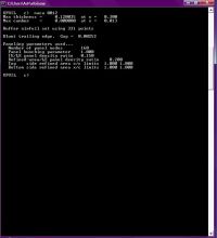
Not quite sure what this means yet, but it's certainly plotting something. All I've downloaded is the three files required for XFOIL, and it seems to be plotting stuff:
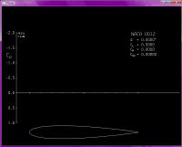
I guess I need to play with it some more
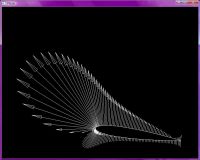

Ash Small, Tue Dec 23 2014, 10:09AM
Ok, just to re-count where I am with this, assuming a drag bucket from Mach 0.5 to Mach 0.7 tip speed, we want hover at Mach 0.5, so we want sufficient Cl for hover with minimum Cd.
We can work this out a number of ways, for example, 'thin airfoil theory' for each blade section, but XFOIL has been proven to work, so if we can get it to run, that's probably the best option.
I'll look into this some more, though.
EDIT: I think I've got XFOIL 6.99 for windows running on my laptop. It's prompting for input. I'll have another look at the user manual

EDIT: I'm reading up on X-Windows, and it looks like there are versions for LINUX. I need to read some more. I'm not sure if we need to use a specific UNIX version yet. There are also versions that run under Windows.
EDIT: "X- Win32 allows remote display of UNIX windows on Windows machines in a normal window alongside the other Windows applications"

Costs $285 though. I'll look for a free equivalent. It does have a 30 day free trial period though.
EDIT: Here's a screenshot of what happened when I entered NACA 0012 into XFOIL. I assume I have to run X-windows at the same time, either on another machine or the same one, but I've not worked out the details yet. It seems to be doing something though, and there are loads of other commands to use


Not quite sure what this means yet, but it's certainly plotting something. All I've downloaded is the three files required for XFOIL, and it seems to be plotting stuff:

I guess I need to play with it some more


Re: Propeller Physics and VABs Program.
Andy, Tue Dec 23 2014, 08:15PM
Old school way of finding the data
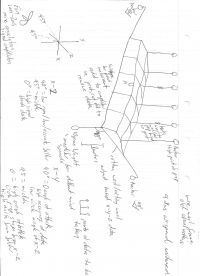
Andy, Tue Dec 23 2014, 08:15PM
Old school way of finding the data


Re: Propeller Physics and VABs Program.
Ash Small, Tue Dec 23 2014, 10:07PM
I think I'm starting to get the hang of it
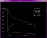
This allows us to analyze the rotor at any section at any sub-sonic velocity. It also tells you if any part of the airflow over the rotor goes super-sonic. In fact, I think it tells us pretty much all we need to know. We do need to input each section manually, though, but it allows us to compare different sections.
I'm pretty busy for a day or two, but I'll play with it some more as and when I get the chance
Ash Small, Tue Dec 23 2014, 10:07PM
I think I'm starting to get the hang of it

This allows us to analyze the rotor at any section at any sub-sonic velocity. It also tells you if any part of the airflow over the rotor goes super-sonic. In fact, I think it tells us pretty much all we need to know. We do need to input each section manually, though, but it allows us to compare different sections.
I'm pretty busy for a day or two, but I'll play with it some more as and when I get the chance

Re: Propeller Physics and VABs Program.
Patrick, Wed Dec 24 2014, 07:01AM
so cool ! thanks for the help, ive seen that airfoil with the arrow vectors somewhere. im continuing to look at the notes youve written. i have to rewind a motor but ill keep checking in.
Patrick, Wed Dec 24 2014, 07:01AM
so cool ! thanks for the help, ive seen that airfoil with the arrow vectors somewhere. im continuing to look at the notes youve written. i have to rewind a motor but ill keep checking in.
Re: Propeller Physics and VABs Program.
Andy, Wed Dec 24 2014, 10:07PM
Hi Patrick
A sidenote on the prop surroundings


May stop the losses from when the Uav is hovering compared to moving at speed.
Andy, Wed Dec 24 2014, 10:07PM
Hi Patrick
A sidenote on the prop surroundings


May stop the losses from when the Uav is hovering compared to moving at speed.
Re: Propeller Physics and VABs Program.
Patrick, Sun Dec 28 2014, 01:12AM
I now attempt to understand a term ive never heard before, "solidity"
Patrick, Sun Dec 28 2014, 01:12AM
I now attempt to understand a term ive never heard before, "solidity"
QUESTION:
I am doing a study on propeller design and have some questions to which I have been unable to answer.
1. I have read and article that claims to have had success with higher efficiencies of propellers at high activity factors. Please could you give me the definition of activity factor? Is this similar to solidarity?
2. I note that some newer propellers use a scimitar shape. What is the reason for using this shape?
ANSWER from Brent Wellman on October 27, 1999:
Good question. This is one that doesn't come up a lot due to the nature of helicopter rotors versus propellers.
Activity factor is a measure of how much power any given propeller can absorb. It is roughly equal to solidity times a constant for any particular prop.
Here are the details:
Solidity is simply the ratio of the total blade area of the propeller to the disk swept out when the prop turns. The blade area is roughly the length (called the radius) times the width (called the chord). That works well for untwisted rectangular blades, but there are few serious props like that, so engineers use integral calculus to figure the area of the blades. They integrate the chord (width) over the radius (length). For reasons known only to them, propeller engineers tend to integrate from 15% of the radius outward while helicopter engineers like to start at 0% (propeller hubs tend to be much larger than helicopter hubs in relation to prop size...).
It is useful to know solidity, because the pressure difference across the prop disk moves the slip stream (propelling the aircraft). The pressure differences between blade surfaces maintain this overall pressure gradient (they *are* wings, after all). The blades though, as rotating wings, will only maintain so much thrust per unit blade area, so knowing the ratio of areas gives you an idea of how fast you can make the slip stream motivate...sorta.
In props, some blade area is better than other blade area.
It turns out that low solidity yields high efficiency. Therefore, low-speed, low-power props tend to have few blades and they are skinny (we say short chord, or high aspect ratio). The Cessna 172 has a two-bladed McCauley prop, and it does just fine with it, thank you.
It turns out that if you really want to drive a prop to high speeds and pump a load of power into it, you need higher solidity. The engineers who worked on this problem in the 1930's developed a prop measure called activity factor. It appears to have been defined to yield a nice number "around" 100, than for any other purpose, but it *does* give an apples-to-apples comparison of propeller designs with respect to their ability to absorb power efficiently.
As I said above, all blade area is not created equal in props. Bits near the tip tend to spin faster, encounter higher dynamic pressures, generate more lift (thrust), sweep over a larger portion of the propeller disk, and so on as compared to bits closer to the spinner. So engineers developed a "power weighted" solidity measurement called "activity factor." It is measured per blade and doesn't account for the number of blades as solidity does.
It is defined as follows (and words are not as good as mathematical notation for this): Activity factor equals (100,000 divided by prop diameter to the fifth power) times the integral, from 15% radius to the tip, of the radius cubed times the chord at that radius, with respect *to* the radius. If you don't have the math, don't sweat it.
Activity factor was important as high speed became important to the sacrifice of efficiency. Prop blades designed for high speed put more area near the tip to put more lifting area where it would do the most good. They also tend to have more blades (4 or 5) for the same reason. Look at the prop on a P-51 Mustang, for instance.
Such paddle-shaped blades are really quite good at high speeds, and are still in use. The C-130 Hercules transport uses the Hamilton Standard Hydramatic constant speed prop. Its activity factor is 162 per blade.
The Cessna 172 prop mentioned above has an activity factor of 103 per blade.
You have described props with a scimitar shape. This was the result of some prop research done at NASA Lewis (now *Glenn*) Research Center in the 70's and 80's in an attempt to design an efficient prop designed to operate at Mach .8 or so (nearly jet transport speeds).
At extremely high power settings, the pressure difference is enough to stall out prop tips. Blade area is moved inboard and the tip is tapered to allow more of the blade area to continue to operate efficiently. Also, if high Mach numbers are seen at the tip, it is useful to sweep back the tips, like the wings of a high-speed transport, and for the same reasons. A swept blade, however, would tend to break off at the base if spun at great speed, therefore, the inner portion is swept *forward* to balance things out (at least overall). The result is a blade the shape of a scimitar.
Such experimental props have been reported to have activity factors of 203 per blade. See NASA-TM-X-73612, Mikkelson, et al, "Design and Performance of Energy Efficient Propellers for Mach 0.8 Cruise." It is available from the Society of Automotive Engineers as paper #770458.
Re: Propeller Physics and VABs Program.
Andy, Sun Dec 28 2014, 01:24AM
Simple answer, its like old wind mills with 20 blades, high torgue but the eff is 10 percent, were as a lift design would be near max eff, if you want to increase torque it would be better that the motor turns a gear that is the same size of the prop, ether way don,t use soldaity as some thing to aim for
Re: Propeller Physics and VABs Program.
Ash Small, Sun Dec 28 2014, 03:47PM
Props with 'high solidity' by definition have 'high disc loading', so have low efficiency. We've already established that we want low disc loading.
He's talking Cessna's here, not 'copters. What we want is something like a conventional heli blade, but because it's fixed, we want a bit of twist and maybe sopme other changes in section.
I think we really just need to consider Mach speed, and lift to drag ratio. The faster the blade section velocity, the smaller section you need to generate required lift, as long as nothing goes supersonic and we stay in the drag bucket.
Ash Small, Sun Dec 28 2014, 03:47PM
Patrick wrote ...
I now attempt to understand a term ive never heard before, "solidity"
.
I now attempt to understand a term ive never heard before, "solidity"
.
Props with 'high solidity' by definition have 'high disc loading', so have low efficiency. We've already established that we want low disc loading.
He's talking Cessna's here, not 'copters. What we want is something like a conventional heli blade, but because it's fixed, we want a bit of twist and maybe sopme other changes in section.
I think we really just need to consider Mach speed, and lift to drag ratio. The faster the blade section velocity, the smaller section you need to generate required lift, as long as nothing goes supersonic and we stay in the drag bucket.
Re: Propeller Physics and VABs Program.
Patrick, Mon Dec 29 2014, 08:18PM
ok we should start with getting and keeping the drag bucket in the first quadrant and the tip below M0.7 ?
Patrick, Mon Dec 29 2014, 08:18PM
ok we should start with getting and keeping the drag bucket in the first quadrant and the tip below M0.7 ?
Re: Propeller Physics and VABs Program.
Andy, Mon Dec 29 2014, 09:23PM
Just been working on a design for a project, thought it might of use to you, the larger numbers are the R axis, with the numbers after the commer the Y axis, cos(Y)/R should equal the X axis, the blue line is the bottom of the blade, and the yellow the top.
Andy, Mon Dec 29 2014, 09:23PM
Just been working on a design for a project, thought it might of use to you, the larger numbers are the R axis, with the numbers after the commer the Y axis, cos(Y)/R should equal the X axis, the blue line is the bottom of the blade, and the yellow the top.
Re: Propeller Physics and VABs Program.
Patrick, Mon Dec 29 2014, 10:17PM
is the yellow line in the drag bucket towards the origin? else i fail to understand . . .
Patrick, Mon Dec 29 2014, 10:17PM
is the yellow line in the drag bucket towards the origin? else i fail to understand . . .
Re: Propeller Physics and VABs Program.
Andy, Mon Dec 29 2014, 10:42PM
Don't know what you mean by drag bucket?
The right side is the front of the blade, the left the back, the top part is 20degrees of mid, the bottom blue line is 5 degrees of mid, with rought values that want mean anything apart from a ratio, 400(say Neutons) to 297 for drag the top side.
Re: Propeller Physics and VABs Program.
Ash Small, Mon Dec 29 2014, 11:14PM
Well, this is the way I see it. Several examples I've seen seem to have a drag bucket from Mach 0.5 to Mach 0.7. It seems standard practice and seems easily feasible to get the drag bucket between these values.
Now these figures are for a 'wing section'. In our case this is 'tip speed', or there abouts.
We need to stay within the drag bucket for efficiency, so the 'operating region' has to be from the bottom of the drag bucket to the top, which implies (I assume) that hover equals Mach 0.5 tip speed and max thrust equals Mach 0.7, or there abouts.
With these parameters fixed (approximately), I suggest we design for hover at Mach 0.5, then 'simulate' at 0.7 to test that no part of the flow goes super sonic, and that everything else is ok, but we primarily design for hover at Mach 0.5.
We then, for each blade section, work out the Mach speed at hover, and use a section with suitable Cl and Cd, then simulate for max speed at that section.
We know disc loading (~5kg/m^2) and disc area (0.5m^2 per rotor). We can work out thrust required and hence Cl. Cd just needs to be kept to a minimum.
We may even still be able to use VABS to work out the 'forces on a beam' thing
EDIT: I'm using Mach numbers for velocity as that is apparently what the Pro's do (and that is what XFOIL uses)
EDIT: I'm assuming it will spend most of it's time at, or around, hover, so we design for max efficiency at around that point, or slightly above, to allow for manouvering, stability, etc.
EDIT: If we use the 'forces on a beam' thing to work out how much CF we need to withstand the thrust, we have our CSA. We then design for the Cl we need using that CSA, while ensuring that Cd remains at a minimum. We then end up with long, thin, lightly loaded, low drag blades.
Ash Small, Mon Dec 29 2014, 11:14PM
Patrick wrote ...
ok we should start with getting and keeping the drag bucket in the first quadrant and the tip below M0.7 ?
ok we should start with getting and keeping the drag bucket in the first quadrant and the tip below M0.7 ?
Well, this is the way I see it. Several examples I've seen seem to have a drag bucket from Mach 0.5 to Mach 0.7. It seems standard practice and seems easily feasible to get the drag bucket between these values.
Now these figures are for a 'wing section'. In our case this is 'tip speed', or there abouts.
We need to stay within the drag bucket for efficiency, so the 'operating region' has to be from the bottom of the drag bucket to the top, which implies (I assume) that hover equals Mach 0.5 tip speed and max thrust equals Mach 0.7, or there abouts.
With these parameters fixed (approximately), I suggest we design for hover at Mach 0.5, then 'simulate' at 0.7 to test that no part of the flow goes super sonic, and that everything else is ok, but we primarily design for hover at Mach 0.5.
We then, for each blade section, work out the Mach speed at hover, and use a section with suitable Cl and Cd, then simulate for max speed at that section.
We know disc loading (~5kg/m^2) and disc area (0.5m^2 per rotor). We can work out thrust required and hence Cl. Cd just needs to be kept to a minimum.
We may even still be able to use VABS to work out the 'forces on a beam' thing

EDIT: I'm using Mach numbers for velocity as that is apparently what the Pro's do
 (and that is what XFOIL uses)
EDIT: I'm assuming it will spend most of it's time at, or around, hover, so we design for max efficiency at around that point, or slightly above, to allow for manouvering, stability, etc.
EDIT: If we use the 'forces on a beam' thing to work out how much CF we need to withstand the thrust, we have our CSA. We then design for the Cl we need using that CSA, while ensuring that Cd remains at a minimum. We then end up with long, thin, lightly loaded, low drag blades.
Re: Propeller Physics and VABs Program.
Patrick, Mon Dec 29 2014, 11:31PM
ok so lets start getting some pulled together dimensions so i can start a mold. then we'll compare to existing props on my dynomometer.
Patrick, Mon Dec 29 2014, 11:31PM
ok so lets start getting some pulled together dimensions so i can start a mold. then we'll compare to existing props on my dynomometer.
Re: Propeller Physics and VABs Program.
Ash Small, Mon Dec 29 2014, 11:42PM
I just edited the above post while you posted this.
I added:
I think, knowing the max thrust required (or thereabouts, we may need to 'tweak' later), we can work out how much CF we need to use, so, therefore, have our CSA.
This, I think, is the first dimension we need
Ash Small, Mon Dec 29 2014, 11:42PM
Patrick wrote ...
ok so lets start getting some pulled together dimensions so i can start a mold. then we'll compare to existing props on my dynomometer.
ok so lets start getting some pulled together dimensions so i can start a mold. then we'll compare to existing props on my dynomometer.
I just edited the above post while you posted this.
I added:
Ash Small wrote ...
.
EDIT: If we use the 'forces on a beam' thing to work out how much CF we need to withstand the thrust, we have our CSA. We then design for the Cl we need using that CSA, while ensuring that Cd remains at a minimum. We then end up with long, thin, lightly loaded, low drag blades.
.
EDIT: If we use the 'forces on a beam' thing to work out how much CF we need to withstand the thrust, we have our CSA. We then design for the Cl we need using that CSA, while ensuring that Cd remains at a minimum. We then end up with long, thin, lightly loaded, low drag blades.
I think, knowing the max thrust required (or thereabouts, we may need to 'tweak' later), we can work out how much CF we need to use, so, therefore, have our CSA.
This, I think, is the first dimension we need

Re: Propeller Physics and VABs Program.
Ash Small, Mon Dec 29 2014, 11:52PM
There are no units on your graph, Andy. This makes it difficult to even begin to interpret
Ash Small, Mon Dec 29 2014, 11:52PM
Andy wrote ...
Just been working on a design for a project, thought it might of use to you, the larger numbers are the R axis, with the numbers after the commer the Y axis, cos(Y)/R should equal the X axis, the blue line is the bottom of the blade, and the yellow the top.

Just been working on a design for a project, thought it might of use to you, the larger numbers are the R axis, with the numbers after the commer the Y axis, cos(Y)/R should equal the X axis, the blue line is the bottom of the blade, and the yellow the top.

There are no units on your graph, Andy. This makes it difficult to even begin to interpret

Re: Propeller Physics and VABs Program.
Andy, Tue Dec 30 2014, 05:11AM
Its based onn 11 values from 10_110, with a x,y value base it on 10mm ,
8.5090 y
5.554 x
17.01
13.56
25.52
16.55
Should be sin(.5540)*34.0361 =
34.0361
17.91
Replace or subtract 10,20,30,40, from each number from right to left
Will fix or update it later
Andy, Tue Dec 30 2014, 05:11AM
Its based onn 11 values from 10_110, with a x,y value base it on 10mm ,
8.5090 y
5.554 x
17.01
13.56
25.52
16.55
Should be sin(.5540)*34.0361 =
34.0361
17.91
Replace or subtract 10,20,30,40, from each number from right to left
Will fix or update it later
Re: Propeller Physics and VABs Program.
Andy, Tue Dec 30 2014, 05:16AM
The top view should be like the apache helo shape with the first the front the second the back
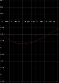
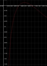
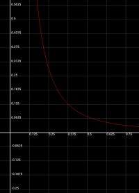
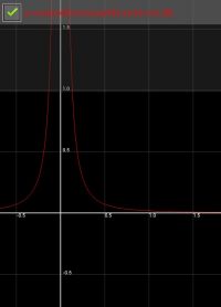
Andy, Tue Dec 30 2014, 05:16AM
The top view should be like the apache helo shape with the first the front the second the back


Re: Propeller Physics and VABs Program.
Andy, Tue Dec 30 2014, 05:18AM
From this
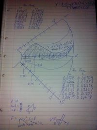
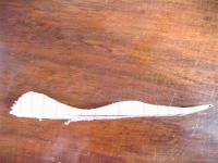
Andy, Tue Dec 30 2014, 05:18AM
From this


mm from point
	20	20			20	20
Back Dims	x	y		Frount Dims	x	y
1	8	-0.03			8	14.75
2	16	13.11			16	7.63
3	24	16.24			24	3.14
4	32	14.51			32	1.13
5	40	10.56			40	0.25
6	48	6.74			48	-0.01
7	56	4.66			56	0.06
8	64	4.8			64	0.21
9	72	6.5			72	0.31
10	80	8.5			80	0.31
11	88	9.64			88	0.22
12	96	9.42			96	0.11
13	104	8.17			104	0.03
14	112	6.69			112	0
15	120	5.83			120	0.02
16	128	5.97			128	0.06
17	136	6.9			136	0.09
18	144	7.98			144	0.1
Re: Propeller Physics and VABs Program.
Patrick, Wed Dec 31 2014, 10:01PM
Im study your work Andy, and appreaciate it. im getting ready to get s-faced here shortly, sa the pre-requiste 2015 arrival.
Patrick, Wed Dec 31 2014, 10:01PM
Im study your work Andy, and appreaciate it. im getting ready to get s-faced here shortly, sa the pre-requiste 2015 arrival.
Re: Propeller Physics and VABs Program.
Ash Small, Wed Dec 31 2014, 10:11PM
I've had a look at Andy's work too Patrick, and from what I can gather, he's assuming a much higher disc loading than we've discussed. At least, that's my impression.
I suggest we consider how much CF we need for hover, then add extra for max thrust, say twice the hover figure, then add a safety margin, so we're looking at, say, three times the CF needed for forces at hover.
Maybe we need more than this, but it sounds about right for a 'starting figure'.
We'll be celebrating here too in a couple of hours.
Ash Small, Wed Dec 31 2014, 10:11PM
Patrick wrote ...
Im study your work Andy, and appreaciate it. im getting ready to get s-faced here shortly, sa the pre-requiste 2015 arrival.
Im study your work Andy, and appreaciate it. im getting ready to get s-faced here shortly, sa the pre-requiste 2015 arrival.
I've had a look at Andy's work too Patrick, and from what I can gather, he's assuming a much higher disc loading than we've discussed. At least, that's my impression.
I suggest we consider how much CF we need for hover, then add extra for max thrust, say twice the hover figure, then add a safety margin, so we're looking at, say, three times the CF needed for forces at hover.
Maybe we need more than this, but it sounds about right for a 'starting figure'.
We'll be celebrating here too in a couple of hours.
Re: Propeller Physics and VABs Program.
Patrick, Wed Dec 31 2014, 10:26PM
ive got 3k fabric of the CF, so 4 to 6 layers of fiberglass and CF should be good.
though wed taper it at the tip, and thicken towards the hub.
Patrick, Wed Dec 31 2014, 10:26PM
ive got 3k fabric of the CF, so 4 to 6 layers of fiberglass and CF should be good.
though wed taper it at the tip, and thicken towards the hub.
Re: Propeller Physics and VABs Program.
Andy, Thu Jan 01 2015, 01:08AM
Happy new year.
The top view can be adjusted, at present a value of 3.1 is the front force with .11 the back force or drag, instead of 20,20, 20,10 can be used which would make it smaller, the data is based on no torque adjust might and only 1 degree eff out of 90, still trying to work out the overall eff.
The data is assuming that drag has the opposite but equal force as lift,.
My design just has more sodility, any way I need to do some mediation on the matter, latter
Re: Propeller Physics and VABs Program.
Patrick, Thu Jan 01 2015, 06:18AM
WOOOOOOOOOOOOOOOOOOOOOOOOOOOOOOOOOOOOOOOOOOOOOOOOO OOOOOOOOOOOOOOOO, 2015 -- Tipsy !
Patrick, Thu Jan 01 2015, 06:18AM
WOOOOOOOOOOOOOOOOOOOOOOOOOOOOOOOOOOOOOOOOOOOOOOOOO OOOOOOOOOOOOOOOO, 2015 -- Tipsy !
Re: Propeller Physics and VABs Program.
Ash Small, Thu Jan 01 2015, 01:41PM
Even if it's thicker near the hub and thinner at the tip, the lowest drag figures will be obtained using just enough uni-directional carbon to give the strength we calculate is required.
Using more carbon than is actually required just increases drag and rotating mass.
We can adjust the angle of attack to give the required Cl from the tip to as close to the hub as possible, without Cd becoming too high.
Re: Propeller Physics and VABs Program.
Patrick, Fri Jan 02 2015, 12:13AM
ok so, unidirectional mostly extending from tip to tip, only clad with 1k on the bottom and then on top.
Patrick, Fri Jan 02 2015, 12:13AM
ok so, unidirectional mostly extending from tip to tip, only clad with 1k on the bottom and then on top.
Re: Propeller Physics and VABs Program.
Ash Small, Fri Jan 02 2015, 12:23AM
Well, the less carbon we use the less the drag. We do need a reasonable safety margin though, we don't want carbon shrapnel at Mach speeds
Ash Small, Fri Jan 02 2015, 12:23AM
Patrick wrote ...
ok so, unidirectional mostly extending from tip to tip, only clad with 1k on the bottom and then on top.
ok so, unidirectional mostly extending from tip to tip, only clad with 1k on the bottom and then on top.
Well, the less carbon we use the less the drag. We do need a reasonable safety margin though, we don't want carbon shrapnel at Mach speeds

Re: Propeller Physics and VABs Program.
Patrick, Sun Jan 04 2015, 03:57AM
Uni-carbon...
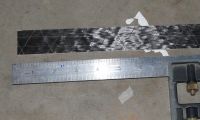
This carbon i layed up is 1k carbon, medium modulus, unidirectional. i can put these together and tailor the thickness in 0.004" layers. The cross pattern is an ultra-thin nylon mesh to keep it in all parrallel while wet.
Patrick, Sun Jan 04 2015, 03:57AM
Uni-carbon...

This carbon i layed up is 1k carbon, medium modulus, unidirectional. i can put these together and tailor the thickness in 0.004" layers. The cross pattern is an ultra-thin nylon mesh to keep it in all parrallel while wet.
Re: Propeller Physics and VABs Program.
Ash Small, Sun Jan 04 2015, 06:20AM
Whether or not we want an external layer of cloth I'm not sure, but if we do, I assume it's best to wrap it around from the back of the blade, so there is a smooth layer over the leading edge.
We do need to do some maths here to determine how much carbon we need, and hence the CSA. (VABS may be useful here, if we have access to a 64 bit machine, or we could work it out the 'old fashioned' way, but I will need to revise the 'forces in a beam' thing and look up the strength of the particular CF we are using.)
XFOIL uses the chord length and profile, so adjusting chord length determines CSA for any NACA profile. (we will need a bit of maths as well, but for any NACA profile, the CSA is a function of chord length)
Ash Small, Sun Jan 04 2015, 06:20AM
Patrick wrote ...
Uni-carbon...

This carbon i layed up is 1k carbon, medium modulus, unidirectional. i can put these together and tailor the thickness in 0.004" layers. The cross pattern is an ultra-thin nylon mesh to keep it in all parrallel while wet.
Uni-carbon...

This carbon i layed up is 1k carbon, medium modulus, unidirectional. i can put these together and tailor the thickness in 0.004" layers. The cross pattern is an ultra-thin nylon mesh to keep it in all parrallel while wet.
Whether or not we want an external layer of cloth I'm not sure, but if we do, I assume it's best to wrap it around from the back of the blade, so there is a smooth layer over the leading edge.
We do need to do some maths here to determine how much carbon we need, and hence the CSA. (VABS may be useful here, if we have access to a 64 bit machine, or we could work it out the 'old fashioned' way, but I will need to revise the 'forces in a beam' thing and look up the strength of the particular CF we are using.)
XFOIL uses the chord length and profile, so adjusting chord length determines CSA for any NACA profile. (we will need a bit of maths as well, but for any NACA profile, the CSA is a function of chord length)
Re: Propeller Physics and VABs Program.
Patrick, Sun Jan 04 2015, 08:32PM
Im having trouble understanding this picture:
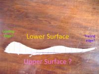
Is it a crossection?
i belive the table equates to the ticks on the foam?
Patrick, Sun Jan 04 2015, 08:32PM
Im having trouble understanding this picture:

Is it a crossection?
i belive the table equates to the ticks on the foam?
Re: Propeller Physics and VABs Program.
Dr. Slack, Sun Jan 04 2015, 09:50PM
Maybe x axis is position on the aerofoil, and y axis is magnitude of the pressure, probably normal to the surface. If you integrate vertically, you'll get the total lift, if you integrate horizontally, the total drag, taking account of the surface normal.
but it might not be.
Re: Propeller Physics and VABs Program.
Patrick, Sun Jan 04 2015, 10:53PM
i didnt realize he maybe meaning the y being magnitude of presure, or lack of.
Patrick, Sun Jan 04 2015, 10:53PM
i didnt realize he maybe meaning the y being magnitude of presure, or lack of.
Re: Propeller Physics and VABs Program.
Ash Small, Mon Jan 05 2015, 12:01AM
When I glanced at the graphs, I assumed one axis was (EDIT: proportional to) Cl and the other Cd, but I didn't fully analyse it.
It's definitely a high disc loading prop, though.
Ash Small, Mon Jan 05 2015, 12:01AM
When I glanced at the graphs, I assumed one axis was (EDIT: proportional to) Cl and the other Cd, but I didn't fully analyse it.
It's definitely a high disc loading prop, though.
Re: Propeller Physics and VABs Program.
Andy, Mon Jan 05 2015, 01:59AM
Patrick the lower side is the direction of rotaion, the larger area end is the hub.
With the top graph, don,t worry about the angle the linear line is, that can or should be horinztail, the x axis is width, the y axis is height, it is the shape the bottom wood blade should be cut to.
The theory is pretty much the drag goes in the oppisite dierction to lift, and what would be good for left, if moved to the bottom or back of the prop will be bad. You have a 180 cicrle with two 45 degree lines which the diection of force comes from, the blade is then changed to make the stuff going into the wind, dierction of rotation have high force, while the back has force going the opposite dierection and needs to be minmized by make the force point out from the hub, while the lift part point into the hub to support rotation.
Re: Propeller Physics and VABs Program.
Patrick, Fri Jan 09 2015, 05:01PM
Im going to petition for an independent study class, and launch a related kickstarter. Once i have some funding, i think ill make more headway faster. we'll be able to see larger props from the chinese, and if there any good.
Patrick, Fri Jan 09 2015, 05:01PM
Im going to petition for an independent study class, and launch a related kickstarter. Once i have some funding, i think ill make more headway faster. we'll be able to see larger props from the chinese, and if there any good.
Re: Propeller Physics and VABs Program.
Ash Small, Fri Jan 09 2015, 05:53PM
Why not feed some data into VABS and XFOIL now that we've established what the relevant data is?
Ash Small, Fri Jan 09 2015, 05:53PM
Patrick wrote ...
Im going to petition for an independent study class, and launch a related kickstarter. Once i have some funding, i think ill make more headway faster. we'll be able to see larger props from the chinese, and if there any good.
Im going to petition for an independent study class, and launch a related kickstarter. Once i have some funding, i think ill make more headway faster. we'll be able to see larger props from the chinese, and if there any good.
Why not feed some data into VABS and XFOIL now that we've established what the relevant data is?
Re: Propeller Physics and VABs Program.
Patrick, Sun Jan 11 2015, 09:54PM
i dont know how to use vabs, i think we'll have to go with XFOIL.
Patrick, Sun Jan 11 2015, 09:54PM
i dont know how to use vabs, i think we'll have to go with XFOIL.
Re: Propeller Physics and VABs Program.
Ash Small, Mon Jan 12 2015, 12:04PM
VABS, from what I've read, will be more useful for working out the forces in the blade, but XFOIL will be useful in working out the profile.
I don't have access to a 64 bit machine, so can't run VABS.
EDIT: We don't need VABS, we can just calculate how much CF is required in the blades.
Ash Small, Mon Jan 12 2015, 12:04PM
Patrick wrote ...
i dont know how to use vabs, i think we'll have to go with XFOIL.
i dont know how to use vabs, i think we'll have to go with XFOIL.
VABS, from what I've read, will be more useful for working out the forces in the blade, but XFOIL will be useful in working out the profile.
I don't have access to a 64 bit machine, so can't run VABS.
EDIT: We don't need VABS, we can just calculate how much CF is required in the blades.
Re: Propeller Physics and VABs Program.
Patrick, Tue Jan 13 2015, 05:48AM
lets focus of cross sections, ill test CF and figure out safety and make-ability.
Patrick, Tue Jan 13 2015, 05:48AM
lets focus of cross sections, ill test CF and figure out safety and make-ability.
Re: Propeller Physics and VABs Program.
Ash Small, Tue Jan 13 2015, 12:39PM
I think we basically need to 'lay up' a 'blade section', then hang weights on the end until it breaks.
We can use the maths and stuff to get us in the ballpark.
We can work out the forces involved at hover, then extrapolate for max rpm.
Once we know how much CF we need, we can input the sections into XFOIL.
Ash Small, Tue Jan 13 2015, 12:39PM
Patrick wrote ...
lets focus of cross sections, ill test CF and figure out safety and make-ability.
lets focus of cross sections, ill test CF and figure out safety and make-ability.
I think we basically need to 'lay up' a 'blade section', then hang weights on the end until it breaks.
We can use the maths and stuff to get us in the ballpark.
We can work out the forces involved at hover, then extrapolate for max rpm.
Once we know how much CF we need, we can input the sections into XFOIL.
Re: Propeller Physics and VABs Program.
Patrick, Tue Jan 13 2015, 10:46PM
Ill start tonight.
Patrick, Tue Jan 13 2015, 10:46PM
Ill start tonight.
Re: Propeller Physics and VABs Program.
Patrick, Thu Jan 15 2015, 08:08AM
Lay-up is slowed due to cold temp, so im waiting for the bend test.
Patrick, Thu Jan 15 2015, 08:08AM
Lay-up is slowed due to cold temp, so im waiting for the bend test.
Re: Propeller Physics and VABs Program.
Ash Small, Thu Jan 15 2015, 03:17PM
Based on the design we've discussed, each rotor exerts a force equivalent to 2.5kg @ hover, so maybe twice this (as a ballpark figure) at max RPM, so @ 2.5kg per blade in a two blade rotor, so I assume we have to be able to hang 2.5kg on each blade without too much deformation.
I do need to check the maths, though, this is very approximate. there are also 'safety factors' to consider.
Ash Small, Thu Jan 15 2015, 03:17PM
Patrick wrote ...
Lay-up is slowed due to cold temp, so im waiting for the bend test.
Lay-up is slowed due to cold temp, so im waiting for the bend test.
Based on the design we've discussed, each rotor exerts a force equivalent to 2.5kg @ hover, so maybe twice this (as a ballpark figure) at max RPM, so @ 2.5kg per blade in a two blade rotor, so I assume we have to be able to hang 2.5kg on each blade without too much deformation.
I do need to check the maths, though, this is very approximate. there are also 'safety factors' to consider.
Re: Propeller Physics and VABs Program.
Patrick, Thu Jan 15 2015, 09:51PM
does that 2.5kg speard out as a derivative, with increasing slope from hub to tip ? how much of the 2.5kg is at the itty-bitty tip?
Patrick, Thu Jan 15 2015, 09:51PM
does that 2.5kg speard out as a derivative, with increasing slope from hub to tip ? how much of the 2.5kg is at the itty-bitty tip?
Re: Propeller Physics and VABs Program.
Ash Small, Thu Jan 15 2015, 10:22PM
I can't remember offhand. More lift is generated at the tip. I need to look it up. I do remember it's pretty basic stuff, though. (I always check everything as a matter of course)
The other point to bear in mind is that the forces on the blade will try to deform it as far as angle of attack is concerned. If it deforms by much it won't have the same properties as before it deforms. I don't think this will be a major problem, but we need to keep it in mind.
We obviously want to use the minimum amount of CF we can 'safely' get away with, in order to keep drag down.
I will have a look at the maths soon, I think we're expecting snow next week, so I'll probably have some time to kill
Ash Small, Thu Jan 15 2015, 10:22PM
Patrick wrote ...
does that 2.5kg speard out as a derivative, with increasing slope from hub to tip ? how much of the 2.5kg is at the itty-bitty tip?
does that 2.5kg speard out as a derivative, with increasing slope from hub to tip ? how much of the 2.5kg is at the itty-bitty tip?
I can't remember offhand. More lift is generated at the tip. I need to look it up. I do remember it's pretty basic stuff, though. (I always check everything as a matter of course)
The other point to bear in mind is that the forces on the blade will try to deform it as far as angle of attack is concerned. If it deforms by much it won't have the same properties as before it deforms. I don't think this will be a major problem, but we need to keep it in mind.
We obviously want to use the minimum amount of CF we can 'safely' get away with, in order to keep drag down.
I will have a look at the maths soon, I think we're expecting snow next week, so I'll probably have some time to kill

Re: Propeller Physics and VABs Program.
Patrick, Sun Jan 25 2015, 07:36AM
Sorry ive been missing in action for so long. Had to help parents with some house repair. but im back ! ive got some parts and tests to get back to.
Im hoping to make point-load measurements along the span, then with math turn those coarse points into a fine derivative curve.
Re: Propeller Physics and VABs Program.
Patrick, Mon Feb 02 2015, 07:43AM
ok had some family health issues should be good now.
ive found this,
in which they state:

Im laying up another beam to be loaded from hub towards tip.
from the above math i see that " m-dot-sub-e " equals " Rho-sub-e x A-sub-e x V-sub-e " since the other componets are on both sides.
Im wanting to point-load the span to see how much carbo/glass is needed. As this constant pitch props are constantly accelerated and decelerated, that mass x acceleration eats battery power. So mass of propeller especially at the tip is important to keep down.
two counter requirements are: first, 80% of thrust occurs at the last 50% of radius. second, the propeller is generally weaker were the radial and bending forces are greatest, regardless of material used.
Patrick, Mon Feb 02 2015, 07:43AM
ok had some family health issues should be good now.
ive found this,

in which they state:
Im laying up another beam to be loaded from hub towards tip.
from the above math i see that " m-dot-sub-e " equals " Rho-sub-e x A-sub-e x V-sub-e " since the other componets are on both sides.
Im wanting to point-load the span to see how much carbo/glass is needed. As this constant pitch props are constantly accelerated and decelerated, that mass x acceleration eats battery power. So mass of propeller especially at the tip is important to keep down.
two counter requirements are: first, 80% of thrust occurs at the last 50% of radius. second, the propeller is generally weaker were the radial and bending forces are greatest, regardless of material used.
Re: Propeller Physics and VABs Program.
Ash Small, Wed Feb 04 2015, 06:16PM
I think the 'm.e' is 'mass of aircraft' in this case.
I'm assuming a constant cross sectional area (although not 'constant section') would be easier to lay up (certainly with unidirectional CF.
The mass of the whole prop needs to be kept to a minimum.
Ash Small, Wed Feb 04 2015, 06:16PM
I think the 'm.e' is 'mass of aircraft' in this case.
I'm assuming a constant cross sectional area (although not 'constant section') would be easier to lay up (certainly with unidirectional CF.
The mass of the whole prop needs to be kept to a minimum.
Re: Propeller Physics and VABs Program.
Patrick, Wed Feb 04 2015, 08:37PM
yeah but the mass of the tip integrated over radius matters for effciency of spool up and down, as we do that continuosly for stability.

my kick starter, drones for Other-Than-Military-Purposes.
Patrick, Wed Feb 04 2015, 08:37PM
yeah but the mass of the tip integrated over radius matters for effciency of spool up and down, as we do that continuosly for stability.

my kick starter, drones for Other-Than-Military-Purposes.
Re: Propeller Physics and VABs Program.
Ash Small, Wed Feb 04 2015, 09:50PM
The mass of the whole prop should be kept to a minimum, not just the tip
Ash Small, Wed Feb 04 2015, 09:50PM
Patrick wrote ...
yeah but the mass of the tip integrated over radius matters for effciency of spool up and down, as we do that continuosly for stability.
yeah but the mass of the tip integrated over radius matters for effciency of spool up and down, as we do that continuosly for stability.
The mass of the whole prop should be kept to a minimum, not just the tip

Re: Propeller Physics and VABs Program.
Patrick, Sat Feb 07 2015, 11:45PM
Ive got the 2nd layup it looks good and bad.
First the torsional strength looks exceptionlly good.
but... the span-wise flex is terrible. so im thinking 2 layers of uni-driectional 1k, then diagonal 45x45 degree layup.
Patrick, Sat Feb 07 2015, 11:45PM
Ive got the 2nd layup it looks good and bad.
First the torsional strength looks exceptionlly good.
but... the span-wise flex is terrible. so im thinking 2 layers of uni-driectional 1k, then diagonal 45x45 degree layup.
Re: Propeller Physics and VABs Program.
Ash Small, Sun Feb 08 2015, 01:52PM
Torsional strength needs to be good to ensure the blade angle remains constant.
Some span-wise flex is permissible. On full size 'copters the rotor sags a bit at rest, etc. Centrifugal forces may actually help a bit here
Ash Small, Sun Feb 08 2015, 01:52PM
Patrick wrote ...
Ive got the 2nd layup it looks good and bad.
First the torsional strength looks exceptionlly good.
but... the span-wise flex is terrible. so im thinking 2 layers of uni-driectional 1k, then diagonal 45x45 degree layup.
Ive got the 2nd layup it looks good and bad.
First the torsional strength looks exceptionlly good.
but... the span-wise flex is terrible. so im thinking 2 layers of uni-driectional 1k, then diagonal 45x45 degree layup.
Torsional strength needs to be good to ensure the blade angle remains constant.
Some span-wise flex is permissible. On full size 'copters the rotor sags a bit at rest, etc. Centrifugal forces may actually help a bit here

Re: Propeller Physics and VABs Program.
Ash Small, Mon Feb 09 2015, 12:32AM
I guess the way to simulate what we want is to use something like those spring things that fishermen use to weigh fish to apply a force upwards to the blade tip, at least as far as static measurements go.
Ash Small, Mon Feb 09 2015, 12:32AM
I guess the way to simulate what we want is to use something like those spring things that fishermen use to weigh fish to apply a force upwards to the blade tip, at least as far as static measurements go.
Re: Propeller Physics and VABs Program.
Patrick, Mon Feb 09 2015, 03:40AM
Ill layup a new flat soon.
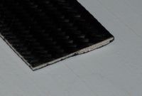
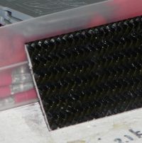
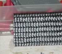
Patrick, Mon Feb 09 2015, 03:40AM
Ash Small wrote ...
like those spring things that fishermen use to weigh fish to apply a force upwards to the blade tip, at least as far as static measurements go.
I was thinking the same thing! and hub to tip pulling.like those spring things that fishermen use to weigh fish to apply a force upwards to the blade tip, at least as far as static measurements go.
Ill layup a new flat soon.


Re: Propeller Physics and VABs Program.
Patrick, Sat Feb 14 2015, 08:12AM
Ash, im wanting to commit to a airfoil cross section from root to tip. Typically the pitch is defined by measurement at 75% radius. But Im thinking we might change the pitch/AOA from a normal prop to our prop, from the root to tip more aggressively.
Patrick, Sat Feb 14 2015, 08:12AM
Ash, im wanting to commit to a airfoil cross section from root to tip. Typically the pitch is defined by measurement at 75% radius. But Im thinking we might change the pitch/AOA from a normal prop to our prop, from the root to tip more aggressively.
Re: Propeller Physics and VABs Program.
Ash Small, Sat Feb 14 2015, 02:04PM
I guess our starting point is the NACA 0012, as used by Bell.
Once we know how much CF to use, we have the chord length. This then gives us the AOA for each section at hover. (from 'thin airfoil theory')
This is where the 'fun' with XFOIL will start.
Ash Small, Sat Feb 14 2015, 02:04PM
I guess our starting point is the NACA 0012, as used by Bell.
Once we know how much CF to use, we have the chord length. This then gives us the AOA for each section at hover. (from 'thin airfoil theory')
This is where the 'fun' with XFOIL will start.
Re: Propeller Physics and VABs Program.
Ash Small, Wed Feb 18 2015, 01:13AM
Maybe we should be trying to produce a NACA 0012 profile with 1 5" radius for spring balance evaluation?
Ash Small, Wed Feb 18 2015, 01:13AM
Maybe we should be trying to produce a NACA 0012 profile with 1 5" radius for spring balance evaluation?
Re: Propeller Physics and VABs Program.
Patrick, Wed Feb 18 2015, 01:32AM
do you mean NACA 0012 from root to a 15" tip?
Patrick, Wed Feb 18 2015, 01:32AM
Ash Small wrote ...
... a NACA 0012 profile with 1 5" radius ...
... a NACA 0012 profile with 1 5" radius ...
do you mean NACA 0012 from root to a 15" tip?
Re: Propeller Physics and VABs Program.
Ash Small, Thu Feb 19 2015, 04:46PM
think so, yes, pretty much. Same as a Bell, as a 'starting point', at least.
Once we know how much CF we need to use, we know the chord length (or we can calculate it), then we just need to work out the angle of attack for each 'section', to obtain hover ar 4000 RPM, or whatever the figure decided was for the bottom end of the drag bucket.
Once we know how much CF we need we can try inputting some meaningful data into XFOIL.
EDIT: I'll try and look up the 'forces in a beam' thing this weekend, I need to refresh my memory, but I do remember it's pretty simple stuff.
Re: Propeller Physics and VABs Program.
Ash Small, Fri Apr 24 2015, 02:28AM
Sorry to double post, but has any progress been made with this recently? Where are we at the moment?
We need some figures.
Ash Small, Fri Apr 24 2015, 02:28AM
Sorry to double post, but has any progress been made with this recently? Where are we at the moment?
We need some figures.
Re: Propeller Physics and VABs Program.
Patrick, Fri Apr 24 2015, 07:23AM
i havent forgotten about this. the profile and loading are still undecided at the moment, but ive made and will show some 3d printed parts to alter the pitch of the span in a clever way.
Also, as a practical and safety matter, ive come up with a way to continuously stretch fiberglass or carbon fiber from tip to hub to tip.
Next, ive captured some shredded rotors for a 700 size helicopter. the guy really augured it in, its internal are surprising.
ill post more tomorrow its mid-night here.
Re: Propeller Physics and VABs Program.
Patrick, Sun Apr 26 2015, 04:23PM
heli blades, ill explain more later.
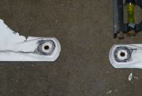

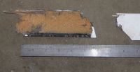
theres some unique features ill mention after work.
Patrick, Sun Apr 26 2015, 04:23PM
heli blades, ill explain more later.


theres some unique features ill mention after work.
Re: Propeller Physics and VABs Program.
Ash Small, Mon Apr 27 2015, 10:14PM
 Fascinating
By the way, I think I may have made an error in the maths somewhere regading RPM, Tip Speed, and Mach1.
I'm not sure how feasible it is to achieve near Mach tipspeed. You don't want to get too close anyway, even when tip speed is nearing Mach 1, if you have any turbulence, some of it can go supersonic. It's about finding a balance
Ash Small, Mon Apr 27 2015, 10:14PM
 Fascinating
By the way, I think I may have made an error in the maths somewhere regading RPM, Tip Speed, and Mach1.
I'm not sure how feasible it is to achieve near Mach tipspeed. You don't want to get too close anyway, even when tip speed is nearing Mach 1, if you have any turbulence, some of it can go supersonic. It's about finding a balance
Re: Propeller Physics and VABs Program.
Patrick, Tue Apr 28 2015, 06:28AM
In depth examination of 700mm helicopter blades.
Ill have more to post but im super tired.
I was given these blades from a fellow hobbyist who had is machine go in full-force and explode to pieces. These blades are being examined here for what can be learned for multirotor use. There are significant differences between constant head speed and multirotor props, but this is still a useful persuit.
i was told there would be a lead whiegt in the tip of each blade, held in place with a fiberglass tow for safety. And that i may not find it since the tips were gone.

this surviving blade will be sectioned off at 4, 9 and 15 inches.
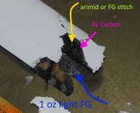
from the original crash damage, the plies can be seen.
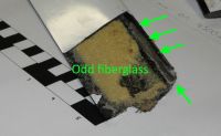
there is a odd placed section of fiberglass but a void too. The top thin surface was carefully removed to reveal more of the interior. Seen here is a foam that wont dissolve in acetone. Im thinking its polyurethane.
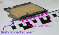
there is mysterious void and beefy fiberglass thats broken and loose.
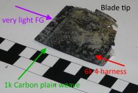
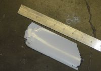

SURPRISE! those voids were missing lead rods running through the leading edge, not the tip! they must have been stripped out from cracking and deceleration forces!
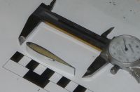
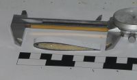
Patrick, Tue Apr 28 2015, 06:28AM
In depth examination of 700mm helicopter blades.
Ill have more to post but im super tired.
I was given these blades from a fellow hobbyist who had is machine go in full-force and explode to pieces. These blades are being examined here for what can be learned for multirotor use. There are significant differences between constant head speed and multirotor props, but this is still a useful persuit.
i was told there would be a lead whiegt in the tip of each blade, held in place with a fiberglass tow for safety. And that i may not find it since the tips were gone.

this surviving blade will be sectioned off at 4, 9 and 15 inches.

from the original crash damage, the plies can be seen.

there is a odd placed section of fiberglass but a void too. The top thin surface was carefully removed to reveal more of the interior. Seen here is a foam that wont dissolve in acetone. Im thinking its polyurethane.

there is mysterious void and beefy fiberglass thats broken and loose.


SURPRISE! those voids were missing lead rods running through the leading edge, not the tip! they must have been stripped out from cracking and deceleration forces!


Re: Propeller Physics and VABs Program.
BigBad, Tue Apr 28 2015, 02:34PM
Interesting, so presumably the lead weights are in the right place that will stop the blades fluttering because it keeps the CofM ahead of the CofL.
BigBad, Tue Apr 28 2015, 02:34PM
Interesting, so presumably the lead weights are in the right place that will stop the blades fluttering because it keeps the CofM ahead of the CofL.
Re: Propeller Physics and VABs Program.
Ash Small, Tue Apr 28 2015, 03:35PM
Are these blades designed for constant RPM, and variable angle of attack (ie swashplate)?
The reason I ask is that, if you have constant A of A, and vary the RPM to control lift, you will be constantly accelerating and deceleration the lead weight, which sounds inefficient.
Also, I'd expect the chord length to be shorter that this. The profile does correspond to a NACA 0012 profile quite well, from first glance, though.
I realise there are practical problems and limitations, and compromises need to be made, but it's certainly worth seeing how others have addressed the issues here.
EDIT: The lead adds inertia to the blade which, when spun up, resists any fluttering, etc., but response will be slower, as you have more mass to accelerate/decelerate, unless you use a swashplate, if my assumptions are correct.
Re: Propeller Physics and VABs Program.
Patrick, Tue Apr 28 2015, 06:13PM
The chord width is 2.4 inches. The 1k plain weave carbon, is at +45 and -45 degrees, while the 6k harness is at 0 and 90 degrees. This gives torsion and flexural strength.

My in progress Kickstarter, i just wish i knew how to get links to appear as clickable text.
Patrick, Tue Apr 28 2015, 06:13PM
BigBad wrote ...
Interesting, so presumably the lead weights are in the right place that will stop the blades fluttering because it keeps the CofM ahead of the CofL.
I never would have realized this.Interesting, so presumably the lead weights are in the right place that will stop the blades fluttering because it keeps the CofM ahead of the CofL.
Ash Small wrote ...
Are these blades designed for constant RPM, and variable angle of attack (ie swashplate)?
Yes.Are these blades designed for constant RPM, and variable angle of attack (ie swashplate)?
Ash Small wrote ...
The reason I ask is that, if you have constant A of A, and vary the RPM to control lift, you will be constantly accelerating and deceleration the lead weight, which sounds inefficient.
EDIT: The lead adds inertia to the blade which, when spun up, resists any fluttering, etc., but response will be slower, as you have more mass to accelerate/decelerate, unless you use a swashplate, if my assumptions are correct.
yes for our purpose totally inefficient. we need the tip to be light weight, but well supported and stiff.The reason I ask is that, if you have constant A of A, and vary the RPM to control lift, you will be constantly accelerating and deceleration the lead weight, which sounds inefficient.
EDIT: The lead adds inertia to the blade which, when spun up, resists any fluttering, etc., but response will be slower, as you have more mass to accelerate/decelerate, unless you use a swashplate, if my assumptions are correct.
The chord width is 2.4 inches. The 1k plain weave carbon, is at +45 and -45 degrees, while the 6k harness is at 0 and 90 degrees. This gives torsion and flexural strength.

My in progress Kickstarter, i just wish i knew how to get links to appear as clickable text.
Re: Propeller Physics and VABs Program.
Patrick, Sat May 02 2015, 05:52AM
New pics with important info. Id like to here from BigBad on this new info.
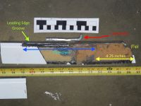
The lead was not the shape or in the place i thought. At its full - undestroyed length, the lead would wheigh 47grams

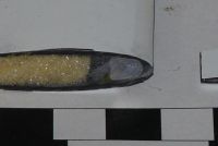


This Blade has been enormously helpful, as has been seeing it in flight, doing +/- 5 g changes. It squeels and whines when they go high alpha at high G.
Only some of this is valuable to our task at hand. But the thickness ad weave has been one such lesson.
Patrick, Sat May 02 2015, 05:52AM
New pics with important info. Id like to here from BigBad on this new info.

The lead was not the shape or in the place i thought. At its full - undestroyed length, the lead would wheigh 47grams


This Blade has been enormously helpful, as has been seeing it in flight, doing +/- 5 g changes. It squeels and whines when they go high alpha at high G.
Only some of this is valuable to our task at hand. But the thickness ad weave has been one such lesson.
Re: Propeller Physics and VABs Program.
BigBad, Sun May 03 2015, 12:37AM
Yeah, so the lead will help with the aerodynamic stability. If it was in the rear edge it would massively destabilise it, it would flutter like crazy. Adding weight to the tip would probably help with flutter a bit too, but leading edge is much more important, and most of it can be further inboard. Angular momentum goes as the square of the distance from the axis, so you want as much of the lead inboard as possible for responsiveness.
Re: Propeller Physics and VABs Program.
Patrick, Mon May 04 2015, 03:45AM
the lead must also keep the rotational inertia up so it builds and fades slowly, so the motor and speed control can keep up.
Patrick, Mon May 04 2015, 03:45AM
the lead must also keep the rotational inertia up so it builds and fades slowly, so the motor and speed control can keep up.
Re: Propeller Physics and VABs Program.
Ash Small, Mon May 04 2015, 09:54AM
Do we know the 'design RPM' of these props, Patrick?
I'm still of the opinion that we want to be looking at solid carbon blades, with a much shorter chord and higher RPM.
The stiffness we need will come from the carbon, unless you can think of anything stiffer and lighter than carbon

Re: Propeller Physics and VABs Program.
Patrick, Thu May 07 2015, 04:07PM
yes for or purposes they would be solid. and if i remember the heli ones were 2,000 rpm.
Patrick, Thu May 07 2015, 04:07PM
yes for or purposes they would be solid. and if i remember the heli ones were 2,000 rpm.
Re: Propeller Physics and VABs Program.
Patrick, Sat May 09 2015, 05:12AM
I can confirm that the carbon fiber 45 and -45 weave is stiff when the strength is needed lengthwise, so thin solid propellers are entirely possible.
Patrick, Sat May 09 2015, 05:12AM
I can confirm that the carbon fiber 45 and -45 weave is stiff when the strength is needed lengthwise, so thin solid propellers are entirely possible.
Re: Propeller Physics and VABs Program.
Ash Small, Sat May 09 2015, 10:28AM
Yep
Ash Small, Sat May 09 2015, 10:28AM
Patrick wrote ...
I can confirm that the carbon fiber 45 and -45 weave is stiff when the strength is needed lengthwise, so thin solid propellers are entirely possible.
I can confirm that the carbon fiber 45 and -45 weave is stiff when the strength is needed lengthwise, so thin solid propellers are entirely possible.
Yep

Re: Propeller Physics and VABs Program.
Patrick, Mon May 11 2015, 05:04AM
so with fixed pitch, were going for a common NACA profile right? Ill print a mold on my 3D printer, then layup some wet CF.
Patrick, Mon May 11 2015, 05:04AM
so with fixed pitch, were going for a common NACA profile right? Ill print a mold on my 3D printer, then layup some wet CF.
Re: Propeller Physics and VABs Program.
Ash Small, Mon May 11 2015, 11:31AM
The 'ideal situation' is where tip speed is as close to Mach 1 as possible, without any turbulence etc exceeding Mach 1
The rotor obviously needs to withstand the forces involved without deforming, and higher RPM helps here too.
Once we know how much carbon we need for stiffness we can calculate chord length and angle of attack for each 'station' along the rotor.
The short chord length and minimal amount of carbon help to reduce drag losses (of the rotor) to a minimum.
Obviously, we need to find a 'workable compromise' based on all the above. We just have to get as close to the optimum as practically possible. We can use XFOIL here to finalise and 'fine tune' things as far as possible.
EDIT: I suspect we can go thinner in section than NACA 0012. It's all about getting sufficient stiffness. Bell obviously felt that the 12% max thickness to chord ratio was required using the materials they used at the time. If we can go thinner, say NACA 0009 or even less, we'll get less rotor drag.
Ash Small, Mon May 11 2015, 11:31AM
Patrick wrote ...
so with fixed pitch, were going for a common NACA profile right? Ill print a mold on my 3D printer, then layup some wet CF.
I suggest we start with the NACA 0012 profile, purely because it's a very common profile and it's used by Bell.so with fixed pitch, were going for a common NACA profile right? Ill print a mold on my 3D printer, then layup some wet CF.
The 'ideal situation' is where tip speed is as close to Mach 1 as possible, without any turbulence etc exceeding Mach 1
The rotor obviously needs to withstand the forces involved without deforming, and higher RPM helps here too.
Once we know how much carbon we need for stiffness we can calculate chord length and angle of attack for each 'station' along the rotor.
The short chord length and minimal amount of carbon help to reduce drag losses (of the rotor) to a minimum.
Obviously, we need to find a 'workable compromise' based on all the above. We just have to get as close to the optimum as practically possible. We can use XFOIL here to finalise and 'fine tune' things as far as possible.
EDIT: I suspect we can go thinner in section than NACA 0012. It's all about getting sufficient stiffness. Bell obviously felt that the 12% max thickness to chord ratio was required using the materials they used at the time. If we can go thinner, say NACA 0009 or even less, we'll get less rotor drag.
Re: Propeller Physics and VABs Program.
Patrick, Mon May 11 2015, 01:35PM
Since im operating near 5000 rpm how do we measure whether there flexing? I dont know if ill have to build a strobe camera or what?
Patrick, Mon May 11 2015, 01:35PM
Since im operating near 5000 rpm how do we measure whether there flexing? I dont know if ill have to build a strobe camera or what?
Re: Propeller Physics and VABs Program.
Ash Small, Wed May 13 2015, 12:09AM
We should be able to calculate it.....extrapolate from stationary measurements.
You said a couple of posts back that two layers of 45 degree cloth seemed stiff enough, or something.
Maybe we don't need a NACA profile, maybe a constant thickness blade will suffice?
That get's us into 'thin airfoil theory', but it should still work in XFOIL.
It doesn't matter if the rotor changes profile a bit, as long as it's predictable.
All we want to do is use the minimum amount of carbon required to achieve the required stiffness for the forces acting on it at 4000 to 5000 RPM. We can calculate the forces.
Ash Small, Wed May 13 2015, 12:09AM
Patrick wrote ...
Since im operating near 5000 rpm how do we measure whether there flexing? I dont know if ill have to build a strobe camera or what?
Since im operating near 5000 rpm how do we measure whether there flexing? I dont know if ill have to build a strobe camera or what?
We should be able to calculate it.....extrapolate from stationary measurements.
You said a couple of posts back that two layers of 45 degree cloth seemed stiff enough, or something.
Maybe we don't need a NACA profile, maybe a constant thickness blade will suffice?
That get's us into 'thin airfoil theory', but it should still work in XFOIL.
It doesn't matter if the rotor changes profile a bit, as long as it's predictable.
All we want to do is use the minimum amount of carbon required to achieve the required stiffness for the forces acting on it at 4000 to 5000 RPM. We can calculate the forces.
Re: Propeller Physics and VABs Program.
Patrick, Wed May 13 2015, 05:42AM
ok lets consider this a reduced complication scenario.
Each blade is a span, attached ridgedely at one end. and prgressively lifted at the tip, with maximum deflection and local force at the tip.
if considered as above, i should be able to predict "upward" propeller force. if i build a span on my work table, and hang lead weights i should find both breaking and deflection measurements. This of course ignores radial "throwing from the hub" force.
the phrase "exploding from the hub force" also works nicely.

Re: Propeller Physics and VABs Program.
Ash Small, Wed May 13 2015, 10:30AM
Centrifugal forces should help us here.
The 'forces in a beam' thing will give us the forces in the blade. At hover, total force on each blade is equivalent to total mass divided by number of blades, etc.
Not sure if this 'bending moment and shear force' calculator will be useful, but it looks like it might be worth trying. There's plenty more tutorials on this stuff out there.
Ash Small, Wed May 13 2015, 10:30AM
Patrick wrote ...
ok lets consider this a reduced complication scenario.
Each blade is a span, attached ridgedely at one end. and prgressively lifted at the tip, with maximum deflection and local force at the tip.
if considered as above, i should be able to predict "upward" propeller force. if i build a span on my work table, and hang lead weights i should find both breaking and deflection measurements. This of course ignores radial "throwing from the hub" force.
the phrase "exploding from the hub force" also works nicely.

Centrifugal forces should help us here.
The 'forces in a beam' thing will give us the forces in the blade. At hover, total force on each blade is equivalent to total mass divided by number of blades, etc.
Not sure if this 'bending moment and shear force' calculator will be useful, but it looks like it might be worth trying. There's plenty more tutorials on this stuff out there.

Re: Propeller Physics and VABs Program.
Ash Small, Wed Jun 03 2015, 12:32AM
I just want to expand on a point I made above regarding NACA profile or constant section thin airfoil.
Having given this some more thought, I've realised that the typical NACA section used for traditional 'copters was probably chosen to facilitate construction with materials available at the time, ie a steel beam was common in these designs, with other materials. The steel was for strength.
This type of construction necessitates a profile similar to a NACA profile.
If modern materials allow a constant thickness thin airfoil using laminated CF, while maintaining the required strength, then a constant thickness thin airfoil section 'should' be more efficient than a typical NACA profile.
I think the rest of the theory still holds, ie greatest efficiency is achieved just before anything goes supersonic, assuming we do the sums correctly.
Re: Propeller Physics and VABs Program.
Patrick, Wed Jun 03 2015, 07:09AM
ive made some mods and relearned some 3d tools in autoCAD. Ive made progress on the 14" prop drone which will be flying in 1-2 days.
Ill print a hub and 4 inches (2 inches to the left and right) just to get some lessons learned. With these big or intricate builds, the first few attempts often "fur-ball" on the table.
Re: Propeller Physics and VABs Program.
Patrick, Mon Jul 13 2015, 09:36PM
ok so im getting the hub good. i dont want the attachment to break and fling the parts off.
Patrick, Mon Jul 13 2015, 09:36PM
ok so im getting the hub good. i dont want the attachment to break and fling the parts off.
Print this page