
Small QCW
loneoceans, Mon Sept 29 2014, 05:50AMHi everyone,
I guess I'm somewhat late to the QCW party, but I thought I'd share a simple and small QCW I finally got around to putting together after occasional on-and-off work. I started putting it together a year ago or so but never got around to finishing it until now. It's still very much a work in progress but I think I've figured out most of it. Here's it so far running at 150V, only half of the 300V I plan to run it at!
Update: Write-up in progress here -

I wanted to build a really simple QCW coil. It runs on a simple asynchronous buck converter via bang-bang control modulation, and I managed to put all the control circuitry on a nice small PCB. The QCW secondary itself is a 3.5 x 5.5" coil with a small spun toroid, and runs on a TO247 IGBT double-bridge which I made another compact PCB for.
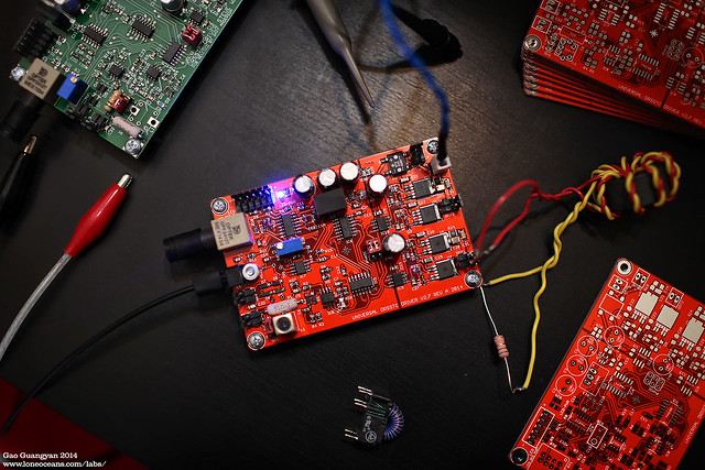
The coil is driven by my version of the UD2 which I've called the UD2.7 (check it out here:
 with primary feedback, and my buck converter I managed to get working.
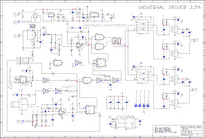
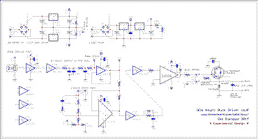
I've also posted my schematics and board layouts on my website. Hopefully this might be useful. Note that they are still experimental and I already have several ideas to improve it.
I haven't got around to tuning it or anything so these are really 'first light' photos. Right now it's running with a 150V ramp about 6 to 7ms long, with a fairly high operating frequency of 470 to 430kHz (winding mistake on my part), but it's pumping out about 100cm (~40 inch) sparks at just above 100A primary current. Each spark consumes about 31J of energy. Next up is a bit more fine tuning and I'll be able to push much more spark when I get it up to 300V :D (recently got a 240V transformer for this). Many thanks to Steve whose conversations really helped.
There isn't much documentation on QCWs so I'll be writing a fairly comprehensive page with all my schematics and designs as well as what I've learned building this coil. Feel free to ask questions.
Short Video of the coil running at 1pps:
 (Some sparks look smaller/disappear because of the camera sensor read-out speed)
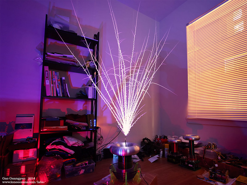
First light of QCW 1.
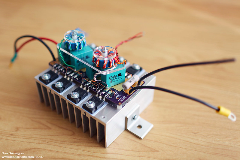
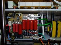
Here's a photo of my bridge. Everything stays basically cold. I like how colorful it came out. I've named it EasyBridge because it's so easy to mount IGBTs on by just soldering the pads directly. This makes replacing IGBTs really easy.
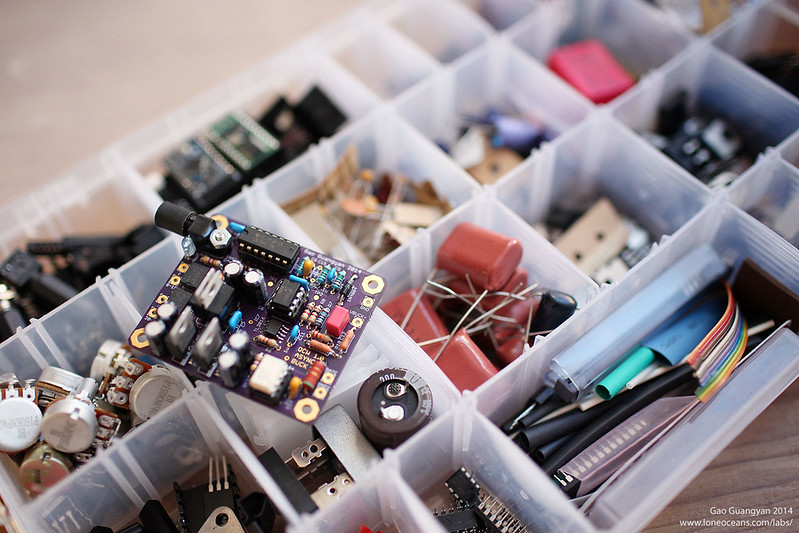
Here's my buck converter controller v1.0 (actually second version)
More to come soon!
Re: Small QCW
kilovolt, Mon Sept 29 2014, 09:40AM
Loneoceans, that's an awesome project, I love it!!! Nice looking coil and great results. Thanks for posting.
Best regards
kilovolt
kilovolt, Mon Sept 29 2014, 09:40AM
Loneoceans, that's an awesome project, I love it!!! Nice looking coil and great results. Thanks for posting.
Best regards
kilovolt
Re: Small QCW
Graham Armitage, Mon Sept 29 2014, 11:54AM
This is impressive. Never tried a QCW coil, but this is inspiring me. Thanks for sharing. You do some awesome work - neat construction. As always your photos are incredible too. Any video of it in operation?
Graham Armitage, Mon Sept 29 2014, 11:54AM
This is impressive. Never tried a QCW coil, but this is inspiring me. Thanks for sharing. You do some awesome work - neat construction. As always your photos are incredible too. Any video of it in operation?
Re: Small QCW
teravolt, Mon Sept 29 2014, 04:55PM
Hi loneoceans, the pictures Are not showing up on your thread can you try again. I am building QCW to and I am always looking for ideas. thanks
teravolt, Mon Sept 29 2014, 04:55PM
Hi loneoceans, the pictures Are not showing up on your thread can you try again. I am building QCW to and I am always looking for ideas. thanks
Re: Small QCW
Sigurthr, Mon Sept 29 2014, 05:23PM
Absolutely beautiful project and results. I haven't tried QCW yet myself either, but this looks extremely enticing, especially running on TO-247's!
Sigurthr, Mon Sept 29 2014, 05:23PM
Absolutely beautiful project and results. I haven't tried QCW yet myself either, but this looks extremely enticing, especially running on TO-247's!
Re: Small QCW
Dr. Dark Current, Mon Sept 29 2014, 06:20PM
Nice work, thumbs up
Dr. Dark Current, Mon Sept 29 2014, 06:20PM
Nice work, thumbs up

Re: Small QCW
..., Mon Sept 29 2014, 06:35PM
Mighty impressive!
..., Mon Sept 29 2014, 06:35PM
Mighty impressive!
Re: Small QCW
BSVi, Mon Sept 29 2014, 07:41PM
I suppose this coil can give longer streamers. Looking forward to see how it operates at max bus voltage.
BSVi, Mon Sept 29 2014, 07:41PM
I suppose this coil can give longer streamers. Looking forward to see how it operates at max bus voltage.
Re: Small QCW
Dr. Dark Current, Mon Sept 29 2014, 11:26PM
So are you running on the upper or lower pole?
Dr. Dark Current, Mon Sept 29 2014, 11:26PM
loneoceans wrote ...
Feel free to ask questions.
Feel free to ask questions.
So are you running on the upper or lower pole?
Re: Small QCW
Mads Barnkob, Tue Sept 30 2014, 08:02AM
Good results. While you think you are late for the QCW party, you are wrong, it would rather seem that you is the first to do a full documentation on your work and from the look of your boards you also have a simpler setup than the first experimental and developing versions we saw from other members :)
Could you please post some more photos of the rest of the setup, like the buck converter bridge, primary coil and capacitor etc
Re: Small QCW
Alex M, Tue Sept 30 2014, 08:14AM
Awesome work and photos!
Alex M, Tue Sept 30 2014, 08:14AM
Awesome work and photos!
Re: Small QCW
loneoceans, Tue Sept 30 2014, 09:02AM
Thanks for the kind words everyone!
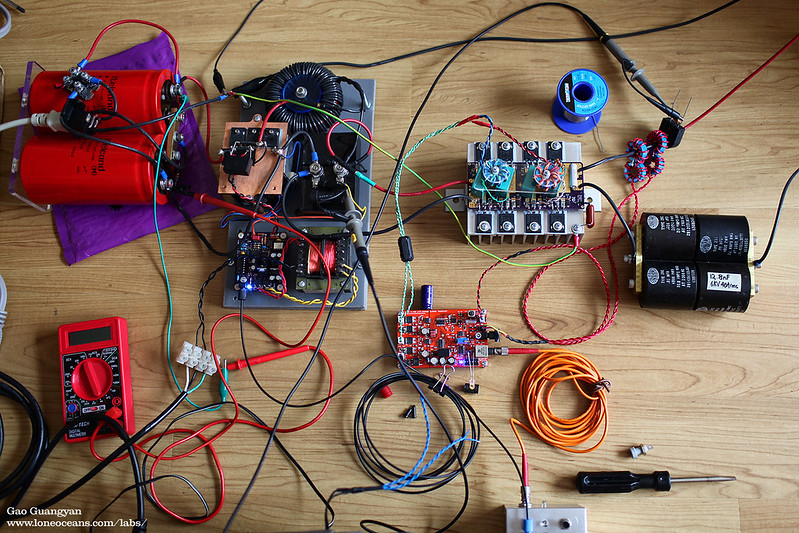
Here's an overview of the current setup. The only change I made so far is replacing the two bus caps (which were in series) to a single one. I was originally using them as a doubler but it was not enough capacitance, so I replaced it with a single cap with FWR input. Other things visible include my red UD2.7, my 12.8nF capacitor, as well as the buck converter on a grey plastic board. Also visible is the signal transformer for the electronics, the buck inductor and capacitor. Controller is the fiber optic controller by an ATtiny45 in a metal box at the bottom right. Probably not as tidy as a phase-shifted bridge, but I think a bus modulator is more versatile and easier to scale up. I'm not sure how happy my TO247 IGBTs are being hard switched in the buck so I'll push them to see if they can handle it! The bridge should be good to 300A I think, so my buck is probably the limiting factor at the moment.
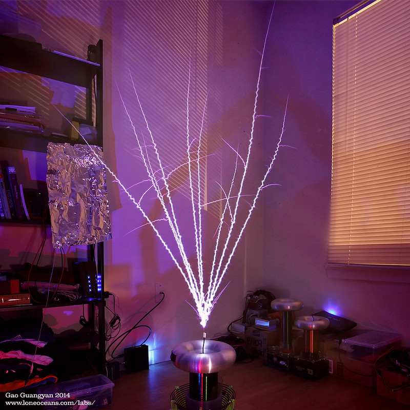
Here's another photo at 150V ramp but in square format :) More to come soon!
loneoceans, Tue Sept 30 2014, 09:02AM
Thanks for the kind words everyone!
teravolt wrote ...
Hi loneoceans, the pictures Are not showing up on your thread can you try again. I am building QCW to and I am always looking for ideas. thanks
The photos are uploaded on flickr and I think they do seem to be having some issues (I get the ocassional image which doesn't load). Maybe wait a bit and try again?Hi loneoceans, the pictures Are not showing up on your thread can you try again. I am building QCW to and I am always looking for ideas. thanks
Graham Armitage wrote ...
This is impressive. Never tried a QCW coil, but this is inspiring me. Thanks for sharing. You do some awesome work - neat construction. As always your photos are incredible too. Any video of it in operation?
Thanks. I'll go record some short clips and post them up soon! This is impressive. Never tried a QCW coil, but this is inspiring me. Thanks for sharing. You do some awesome work - neat construction. As always your photos are incredible too. Any video of it in operation?
Dr. Dark Current wrote ...
So are you running on the upper or lower pole?
I haven't really played around with anything but it's running at the upper pole at the moment starting around 465kHz and dropping to 430kHz at the end of the pulse. Both the secondary and primary are about 400kHz independently of each other. Definitely more investigation to follow here. I was also thinking of making a slightly lower frequency secondary, closer to 350khz or so. I suspect this might also help in reducing side-spark breakouts. I could run it in the lower pole by setting the primary to be lower frequency (this is just a normal feedback drivier so it automatically nudges itself to the upper or lower pole), but my reasonaing was that by running it on the upper pole, the spark will drop the frequency causing the coil to become more and more in tune as the spark grows, as opposed to the other case where it would become out of tune as the spark grows. This isn't the case with a normal DRSSTC because they do not have such high coupling. Ideally I'd like to run the coil at the upper pole but tune the primary lower freq than the secondary.So are you running on the upper or lower pole?
Mads Barnkob wrote ...
Good results. While you think you are late for the QCW party, you are wrong, it would rather seem that you is the first to do a full documentation on your work and from the look of your boards you also have a simpler setup than the first experimental and developing versions we saw from other members :)
Could you please post some more photos of the rest of the setup, like the buck converter bridge, primary coil and capacitor etc
Thanks! Been a bit busy these few days but I'll continue to post more. I tried to make the setup as simple as I could, and I'm glad to see it working out.Good results. While you think you are late for the QCW party, you are wrong, it would rather seem that you is the first to do a full documentation on your work and from the look of your boards you also have a simpler setup than the first experimental and developing versions we saw from other members :)
Could you please post some more photos of the rest of the setup, like the buck converter bridge, primary coil and capacitor etc

Here's an overview of the current setup. The only change I made so far is replacing the two bus caps (which were in series) to a single one. I was originally using them as a doubler but it was not enough capacitance, so I replaced it with a single cap with FWR input. Other things visible include my red UD2.7, my 12.8nF capacitor, as well as the buck converter on a grey plastic board. Also visible is the signal transformer for the electronics, the buck inductor and capacitor. Controller is the fiber optic controller by an ATtiny45 in a metal box at the bottom right. Probably not as tidy as a phase-shifted bridge, but I think a bus modulator is more versatile and easier to scale up. I'm not sure how happy my TO247 IGBTs are being hard switched in the buck so I'll push them to see if they can handle it! The bridge should be good to 300A I think, so my buck is probably the limiting factor at the moment.

Here's another photo at 150V ramp but in square format :) More to come soon!
Re: Small QCW
Steve Conner, Tue Sept 30 2014, 09:18AM
Well done, this looks great! As others have said, you will be the first to actually document a QCW build.
Steve Conner, Tue Sept 30 2014, 09:18AM
Well done, this looks great!
 As others have said, you will be the first to actually document a QCW build.
Re: Small QCW
teravolt, Tue Sept 30 2014, 12:42PM
nice
teravolt, Tue Sept 30 2014, 12:42PM
nice
Re: Small QCW
Dr. Dark Current, Tue Sept 30 2014, 06:49PM
Thanks for the info
Dr. Dark Current, Tue Sept 30 2014, 06:49PM
Thanks for the info

Re: Small QCW
hen918, Tue Sept 30 2014, 08:37PM
Very nice! But can anyone tell me, what does QCW stand for? I know what it is, but I cannot find it's full name anywhere!
hen918, Tue Sept 30 2014, 08:37PM
Very nice! But can anyone tell me, what does QCW stand for? I know what it is, but I cannot find it's full name anywhere!
Re: Small QCW
Dr. Dark Current, Tue Sept 30 2014, 08:41PM
quasi-continuous wave... its a somewhat misleading name, I would call it "ramped SSTC"
Dr. Dark Current, Tue Sept 30 2014, 08:41PM
quasi-continuous wave... its a somewhat misleading name, I would call it "ramped SSTC"

Re: Small QCW
Ash Small, Tue Sept 30 2014, 09:32PM
Following on from Mads' comments above, regarding QCW 'documentation', could someone (loneoceans, maybe?) post a 'waveform' of Quasi-Continuous Wave operation, please?
Ash Small, Tue Sept 30 2014, 09:32PM
Following on from Mads' comments above, regarding QCW 'documentation', could someone (loneoceans, maybe?) post a 'waveform' of Quasi-Continuous Wave operation, please?
Re: Small QCW
loneoceans, Tue Sept 30 2014, 10:46PM
I have a waveform capture of a single ~7ms ramp from 30V to about 150V with a peak current of just about 120A.
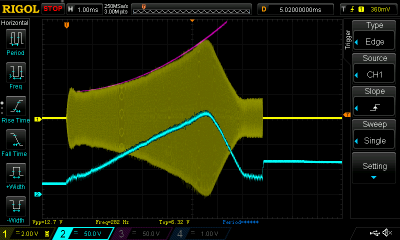
Above shows a capture of the primary current in yellow and the buck (blue) output into the inverter in a single shot. Here you can see the interrupter pulse about 7.8ms long (probably a bit too long at the end after it ramps down, so I'll fix my interrupter code soon). In this particular pulse, the current goes up to about 126A just below my current OCD limit. The bus floats at about 30V. Note how at the end of the ramp (where the primary current is about 30A), when the interrupter cuts, the current in the inductor causes the jump in the bus voltage (remember this is an async buck), which then decays through my 4.7k bleeder resistor across my output cap. This has a 3RC value of 406ms, which is sufficient for the low BPS I am currently running at. I plan to improve the bleeder circuit for cleaning up the spike (or simply dropping the ramp to 0 before going up to 30V again, or a small transistor to discharge the filter cap after each pulse).
Another note - I was never really sure what sort of load a high-Z tesla coil would be. The trace above of the primary current may provide some insight. I realized that the envelop looked very much quadratic, and sure enough, I fitted a quadratic line to it and it looks almost perfect (pink line). Now with normal resonance at a fixed bus input, I noticed that the current rises basically linearly. Since the voltage in the primary tank goes up linearly, this implies the load should be constant. With the voltage now increasing from our buck converter, we can think of the voltage increase as a sum of an arithmetic series, which is quadratic (n^2+n /2), again suggesting that the load (tesla coil) is somewhat constant like a resistor. Not sure if this makes sense. This implies that an open-loop control might just work for an even simpler design.
Indeed QCW is somewhat of a misnomer I guess. It's interesting to compare it with what I got for my Ramped SSTC 3 (or 'fake QCW!'). See my thread for that coil here:

The way I see how a 'QCW DRSSTC' is different from a ramped SSTC is that the QCW is simply a ramped SSTC employing a resonant capacitor which allows for much greater primary current. An easy way is to think of it canceling the impedance of the primary coil.
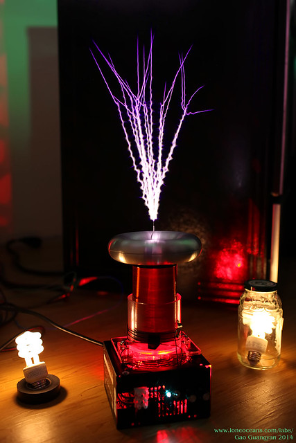
This little coil made about foot long sparks with about 3.5ms ramp about 30A peak in sync with 208V mains (it's just a normal half bridge SSTC), so it really is kind of like a baby QCW I guess. But much of the fun in a QCW is getting the buck converter (or your phase shift) working! This also allows for longer ramps and more fun in making your own ramp profiles.
loneoceans, Tue Sept 30 2014, 10:46PM
Ash Small wrote ...
Following on from Mads' comments above, regarding QCW 'documentation', could someone (loneoceans, maybe?) post a 'waveform' of Quasi-Continuous Wave operation, please?
Following on from Mads' comments above, regarding QCW 'documentation', could someone (loneoceans, maybe?) post a 'waveform' of Quasi-Continuous Wave operation, please?
I have a waveform capture of a single ~7ms ramp from 30V to about 150V with a peak current of just about 120A.

Above shows a capture of the primary current in yellow and the buck (blue) output into the inverter in a single shot. Here you can see the interrupter pulse about 7.8ms long (probably a bit too long at the end after it ramps down, so I'll fix my interrupter code soon). In this particular pulse, the current goes up to about 126A just below my current OCD limit. The bus floats at about 30V. Note how at the end of the ramp (where the primary current is about 30A), when the interrupter cuts, the current in the inductor causes the jump in the bus voltage (remember this is an async buck), which then decays through my 4.7k bleeder resistor across my output cap. This has a 3RC value of 406ms, which is sufficient for the low BPS I am currently running at. I plan to improve the bleeder circuit for cleaning up the spike (or simply dropping the ramp to 0 before going up to 30V again, or a small transistor to discharge the filter cap after each pulse).
Another note - I was never really sure what sort of load a high-Z tesla coil would be. The trace above of the primary current may provide some insight. I realized that the envelop looked very much quadratic, and sure enough, I fitted a quadratic line to it and it looks almost perfect (pink line). Now with normal resonance at a fixed bus input, I noticed that the current rises basically linearly. Since the voltage in the primary tank goes up linearly, this implies the load should be constant. With the voltage now increasing from our buck converter, we can think of the voltage increase as a sum of an arithmetic series, which is quadratic (n^2+n /2), again suggesting that the load (tesla coil) is somewhat constant like a resistor. Not sure if this makes sense. This implies that an open-loop control might just work for an even simpler design.
Dr. Dark Current wrote ...
quasi-continuous wave... its a somewhat misleading name, I would call it "ramped SSTC"
quasi-continuous wave... its a somewhat misleading name, I would call it "ramped SSTC"

Indeed QCW is somewhat of a misnomer I guess. It's interesting to compare it with what I got for my Ramped SSTC 3 (or 'fake QCW!'). See my thread for that coil here:


The way I see how a 'QCW DRSSTC' is different from a ramped SSTC is that the QCW is simply a ramped SSTC employing a resonant capacitor which allows for much greater primary current. An easy way is to think of it canceling the impedance of the primary coil.

This little coil made about foot long sparks with about 3.5ms ramp about 30A peak in sync with 208V mains (it's just a normal half bridge SSTC), so it really is kind of like a baby QCW I guess. But much of the fun in a QCW is getting the buck converter (or your phase shift) working! This also allows for longer ramps and more fun in making your own ramp profiles.
Re: Small QCW
zzz_julian_zzz, Wed Oct 01 2014, 11:14AM
Nice work there my friend ! good results indeed. I'm currently building my QCWDRSSTC too at the moment and having similar results with yours :) sooner i'll be posting my results too :) the only difference I think is that I don't have plan on selling anything heheh :) again nice QCW coil!
Re: Small QCW
Steve Conner, Wed Oct 01 2014, 11:58AM
Nice scope shots! What scope are you using? I'm thinking of replacing my ancient HP 54600B.
Steve Conner, Wed Oct 01 2014, 11:58AM
Nice scope shots!
 What scope are you using? I'm thinking of replacing my ancient HP 54600B.
Re: Small QCW
teravolt, Wed Oct 01 2014, 01:39PM
where do you get the purple boards made
teravolt, Wed Oct 01 2014, 01:39PM
where do you get the purple boards made
Re: Small QCW
loneoceans, Wed Oct 01 2014, 04:15PM
I'm running it around 1Hz because I don't have a variac so my power line is going through a 25 Ohm resistor. This was to prevent blowing my breaker with the big bus cap, but limits my bps. I also found that some of the sparks don't show up or get cut in strange places, mostly because of the sensor readout. I'm currently winding a new coil and focusing on making a more polished setup.
loneoceans, Wed Oct 01 2014, 04:15PM
zzz_julian_zzz wrote ...
Nice work there my friend ! good results indeed. I'm currently building my QCWDRSSTC too at the moment and having similar results with yours :) sooner i'll be posting my results too :) the only difference I think is that I don't have plan on selling anything heheh :) again nice QCW coil!
That sounds great! Was never planning on making the coil for sale though, but I will be posting up all my schematics and designs. I just thought that I had some extra boards leftover and maybe people will be interested, which also helps off-set a bit of my development cost. :) Simply selling at basically cost price (updated above). I get my purple PCBs at OSHpark which are quite pricy, but their fast turnaround and high quality makes them worth it I think, otherwise I send my boards for fab in China. I heard that APcircuits/4pcb has good student deals too.Nice work there my friend ! good results indeed. I'm currently building my QCWDRSSTC too at the moment and having similar results with yours :) sooner i'll be posting my results too :) the only difference I think is that I don't have plan on selling anything heheh :) again nice QCW coil!
Steve Conner wrote ...
Nice scope shots! What scope are you using? I'm thinking of replacing my ancient HP 54600B.
I highly recommend the Rigol DS1000 line! I bought the DS1074z a few months ago and it's fantastic, and probably the 2nd best value scope on the market right now ($550 for 4 channels 70Mhz 1Gs/s huge memory, beautiful screen, and hackable to 100Mhz). In fact, Rigol just released their DS1054z model just a few weeks ago for $399, which I think makes the -The Best- value scope on the market right now by far, and from the looks of it, it might be hackable to 100Mhz (usually $800+), since it simply looks like it could be simply a firmware change. For even better performance, I'd recommend the 2000 series. Their MSO line is great too if you do signal analysis. :)Nice scope shots!
 What scope are you using? I'm thinking of replacing my ancient HP 54600B.
I'm running it around 1Hz because I don't have a variac so my power line is going through a 25 Ohm resistor. This was to prevent blowing my breaker with the big bus cap, but limits my bps. I also found that some of the sparks don't show up or get cut in strange places, mostly because of the sensor readout. I'm currently winding a new coil and focusing on making a more polished setup.
Re: Small QCW
teravolt, Wed Oct 01 2014, 04:49PM
what value are you using for your SMPS snuber filter cap? I found 20uf and 15uf on eBay. and did you try any other values
teravolt, Wed Oct 01 2014, 04:49PM
what value are you using for your SMPS snuber filter cap? I found 20uf and 15uf on eBay. and did you try any other values
Re: Small QCW
dexter, Wed Oct 01 2014, 05:59PM
one thing i didn't get from that thread: the buss cap needs to be omitted so that the coil produce swords like sparks?
dexter, Wed Oct 01 2014, 05:59PM
loneoceans wrote ...
Indeed QCW is somewhat of a misnomer I guess. It's interesting to compare it with what I got for my Ramped SSTC 3 (or 'fake QCW!'). See my thread for that coil here:
Indeed QCW is somewhat of a misnomer I guess. It's interesting to compare it with what I got for my Ramped SSTC 3 (or 'fake QCW!'). See my thread for that coil here:

one thing i didn't get from that thread: the buss cap needs to be omitted so that the coil produce swords like sparks?
Re: Small QCW
Thomas W, Wed Oct 01 2014, 08:34PM
Still haven't got around to building a single tesla coil of my own.... This is really impressive, you may just inspire me to actually get round to doing so! :)
Thomas W, Wed Oct 01 2014, 08:34PM
Still haven't got around to building a single tesla coil of my own.... This is really impressive, you may just inspire me to actually get round to doing so! :)
Re: Small QCW
Uspring, Thu Oct 02 2014, 10:31AM
Very pretty sparks. Congratulations
loneoceans wrote:
Say you tune your primary to 350kHz. You'll then run on the lower pole, which is initially located at 328kHz. The difference between operating and secondary fres is then 72kHz. Under arc load, the poles will be located at 283 and 385kHz. I'm not sure, whether the coil will stay at the lower pole, but if that's the case the difference will be 300Khz - 283KHz = 17 kHz, i.e. very well in tune. It might switch to the upper pole, though, where the difference is 85kHz. So lower pole operation would be the better choice, well, if it stays there.
Uspring, Thu Oct 02 2014, 10:31AM
Very pretty sparks. Congratulations

loneoceans wrote:
I haven't really played around with anything but it's running at the upper pole at the moment starting around 465kHz and dropping to 430kHz at the end of the pulse. Both the secondary and primary are about 400kHz independently of each other.Interesting data. From the frequency values you provided, coupling seems to be about 0.26. The drop in operating frequency implies a drop of secondary res f from 400kHz to about 300kHz due to arc loading, i.e. effective top capacitance rises by about 80%!
I could run it in the lower pole by setting the primary to be lower frequency (this is just a normal feedback drivier so it automatically nudges itself to the upper or lower pole), but my reasonaing was that by running it on the upper pole, the spark will drop the frequency causing the coil to become more and more in tune as the spark grows, as opposed to the other case where it would become out of tune as the spark grows.What matters wrt to tuning is the difference between operating frequency and secondary fres. Initially this is 465kHz - 400Khz = 65kHz. At the end we have 430kHz - 300kHz = 130KHz, so actually your coil goes out of tune at the end of the burst. This is probably not a big issue, since arc loading also widens the secondary resonance curve, so that the effect of detuning becomes less noticeable.
Say you tune your primary to 350kHz. You'll then run on the lower pole, which is initially located at 328kHz. The difference between operating and secondary fres is then 72kHz. Under arc load, the poles will be located at 283 and 385kHz. I'm not sure, whether the coil will stay at the lower pole, but if that's the case the difference will be 300Khz - 283KHz = 17 kHz, i.e. very well in tune. It might switch to the upper pole, though, where the difference is 85kHz. So lower pole operation would be the better choice, well, if it stays there.
Ideally I'd like to run the coil at the upper pole but tune the primary lower freq than the secondary.You'll need special drivers to do that. Steve Conner has been doing that, but from recent posts I'm not sure, whether he still thinks it's a great idea, like I do.
Another note - I was never really sure what sort of load a high-Z tesla coil would be. The trace above of the primary current provides some insight. I realized that the envelop looked very much quadratic, and sure enough, I fitted a quadratic line to it and it looks almost perfect (pink line). Now with normal resonance at a fixed bus input, I noticed that the current rises basically linearly. Since the voltage in the primary tank goes up linearly, this implies the load should be constant. With the voltage now increasing from our buck converter, we can think of the voltage increase as a sum of an arithmetic series, which is quadratic (n^2+n /2), again suggesting that the load (tesla coil) is somewhat constant like a resistor.I don't quite understand that. You have quite a lot of primary current initially, which suggests, that arc load doesn't play a big role and primary current is mostly limited by loss resistances in the primary. From then on primary current increases at a much slower rate than the increase of bus voltage implies, so that the primary looks more like a constant current sink. Primary current mostly picks up during the end of the burst, which might be due to it going more out of tune.
Re: Small QCW
Steve Conner, Thu Oct 02 2014, 10:39AM
Yes, I am still doing it and I think I persuaded Steve Ward to start doing it too.
What I discovered is that in the usual kind of DRSSTC, with low impedance and short burst length, it doesn't make a huge difference. The burst has few enough cycles that both pole frequencies must be considered to be present, you can't say for sure that the system is operating on one or the other, and you can't really persuade a PLL to lock definitively to one or the other.
However, it most certainly makes a difference for high impedance DRSSTCs with long burst length, like my original Mjollnir, my newer AG2 and the coils Arc Attack have been building lately. It is also the best operating mode for QCWs.
And finally, it turned out to be the most stable operating point for Odin, though I think it would probably work exactly the same with less switching losses if I substituted a UD2.x for the PLL and let it switch at the zero crossings.
Steve Conner, Thu Oct 02 2014, 10:39AM
wrote ...
Ideally I'd like to run the coil at the upper pole but tune the primary lower freq than the secondary.
Ideally I'd like to run the coil at the upper pole but tune the primary lower freq than the secondary.
wrote ...
Steve Conner has been doing that, but from recent posts I'm not sure, whether he still thinks it's a great idea
Steve Conner has been doing that, but from recent posts I'm not sure, whether he still thinks it's a great idea
Yes, I am still doing it and I think I persuaded Steve Ward to start doing it too.

What I discovered is that in the usual kind of DRSSTC, with low impedance and short burst length, it doesn't make a huge difference. The burst has few enough cycles that both pole frequencies must be considered to be present, you can't say for sure that the system is operating on one or the other, and you can't really persuade a PLL to lock definitively to one or the other.
However, it most certainly makes a difference for high impedance DRSSTCs with long burst length, like my original Mjollnir, my newer AG2 and the coils Arc Attack have been building lately. It is also the best operating mode for QCWs.
And finally, it turned out to be the most stable operating point for Odin, though I think it would probably work exactly the same with less switching losses if I substituted a UD2.x for the PLL and let it switch at the zero crossings.
Re: Small QCW
loneoceans, Thu Oct 02 2014, 11:02PM
That's correct. This way the inverter will be powered directly from the rising voltage wave of the mains AC. My SSTC 3 board had provision for a bus capacitor on board because I wanted to make it a general purpose platform for normal SSTC use, as well as DRSSTC operation with the addition of an external resonant cap.
Thanks for the useful analysis. I cannot claim to understand drsstc theory extremely well, but here are my thoughts. Also for more reference, my secondary + toroid resonates at 408kHz by itself, and the primary in its current configuration resonates at 392khz. Together, the system has poles at a measured 340 and 482kHz, close to the calculated values of 340 and 479 with my JavaTC k of 0.33. However at the start of the pulse, I did measure 465kHz (I'll go do another measurement nearer to front of the pulse in case it actually started higher), with 430kHz or so at peak current. I had assumed that tuning was referenced to the secondary frequency (400kHz), but (as you pointed out) I did not take into account capacitive loading dropping the secondary freq. This was the reason why I thought upper pole operation would be better but I'm glad you pointed this out. What you says makes sense if the secondary does indeed drop to 300kHz. By adding a 1m wire on the top of the toroid, the centre frequency of the system drops from 408kHz to 310kHz. I also measured the new system frequencies with my primary at 358khz, giving 327, 410, 457kHz. So my question is - How do you calculate the poles of a system with differing primary and secondary frequencies (not sure if I missed out some first order equation somewhere otherwise I'll just model it), and why would there be a tendency for the system to go to the higher pole?
As requested, here's a short video of it running at about 1bps! Excuse the poor quality, will take more soon:
Some sparks look smaller/disappear because of the camera sensor read-out speed. I promise the sparks sound much more quiet in a real life, like a thump instead of what it sounds like in the video.
loneoceans, Thu Oct 02 2014, 11:02PM
dexter wrote ...
one thing i didn't get from that thread: the buss cap needs to be omitted so that the coil produce swords like sparks?
one thing i didn't get from that thread: the buss cap needs to be omitted so that the coil produce swords like sparks?
That's correct. This way the inverter will be powered directly from the rising voltage wave of the mains AC. My SSTC 3 board had provision for a bus capacitor on board because I wanted to make it a general purpose platform for normal SSTC use, as well as DRSSTC operation with the addition of an external resonant cap.
Uspring wrote ...
Interesting data. From the frequency values you provided, coupling seems to be about 0.26. The drop in operating frequency implies a drop of secondary res f from 400kHz to about 300kHz due to arc loading, i.e. effective top capacitance rises by about 80%! What matters wrt to tuning is the difference between operating frequency and secondary fres. Initially this is 465kHz - 400Khz = 65kHz. At the end we have 430kHz - 300kHz = 130KHz, so actually your coil goes out of tune at the end of the burst. This is probably not a big issue, since arc loading also widens the secondary resonance curve, so that the effect of detuning becomes less noticeable.
Say you tune your primary to 350kHz. You'll then run on the lower pole, which is initially located at 328kHz. The difference between operating and secondary fres is then 72kHz. Under arc load, the poles will be located at 283 and 385kHz. I'm not sure, whether the coil will stay at the lower pole, but if that's the case the difference will be 300Khz - 283KHz = 17 kHz, i.e. very well in tune. It might switch to the upper pole, though, where the difference is 85kHz. So lower pole operation would be the better choice, well, if it stays there.
Thanks for the useful analysis. I cannot claim to understand drsstc theory extremely well, but here are my thoughts. Also for more reference, my secondary + toroid resonates at 408kHz by itself, and the primary in its current configuration resonates at 392khz. Together, the system has poles at a measured 340 and 482kHz, close to the calculated values of 340 and 479 with my JavaTC k of 0.33. However at the start of the pulse, I did measure 465kHz (I'll go do another measurement nearer to front of the pulse in case it actually started higher), with 430kHz or so at peak current. I had assumed that tuning was referenced to the secondary frequency (400kHz), but (as you pointed out) I did not take into account capacitive loading dropping the secondary freq. This was the reason why I thought upper pole operation would be better but I'm glad you pointed this out. What you says makes sense if the secondary does indeed drop to 300kHz. By adding a 1m wire on the top of the toroid, the centre frequency of the system drops from 408kHz to 310kHz. I also measured the new system frequencies with my primary at 358khz, giving 327, 410, 457kHz. So my question is - How do you calculate the poles of a system with differing primary and secondary frequencies (not sure if I missed out some first order equation somewhere otherwise I'll just model it), and why would there be a tendency for the system to go to the higher pole?
Uspring wrote ...
You'll need special drivers to do that. Steve Conner has been doing that, but from recent posts I'm not sure, whether he still thinks it's a great idea, like I do.
What I plan to try is to make a small adjustable oscillator which feeds a weak signal into the UD feedback, which I will adjust to lower pole frequency. Hopefully this allows the coil to start off at the lower pole before the feedback is stronger and 'over-rides' the signal. I'm not sure if this will work but I'll try this out over the next few days. Finally, what you said about the primary current makes sense too; I'll continue thinking about it. You'll need special drivers to do that. Steve Conner has been doing that, but from recent posts I'm not sure, whether he still thinks it's a great idea, like I do.
As requested, here's a short video of it running at about 1bps! Excuse the poor quality, will take more soon:

Some sparks look smaller/disappear because of the camera sensor read-out speed. I promise the sparks sound much more quiet in a real life, like a thump instead of what it sounds like in the video.
Re: Small QCW
Goodchild, Fri Oct 03 2014, 06:56AM
Very nice QCW build, I also love your photography.
Your primary current waveshape is very intriguing. With a linear ramp on the input, my geuss is that your system impedance is low enough to start showing it's true nature. Normally you see a "close to linear" response of the primary current envelop with a linear change in modules voltage. This exponential growth of the envelop I bet is alway why you are seeing more branching than normal than with most other QCWs.
Great build can't wait to see more.
Re: Small QCW
Uspring, Fri Oct 03 2014, 03:17PM
flowerpole=sqrt( (fp²+fs²-sqrt( (fp²-fs²)² + 4*k²*fp²*fs² )) / (2*(1-k²) )
Arc loading will make the secondary fres drop from the above the primary fres to below it. Probably that won't make the system switch poles. But it does make a difference when you start ramping up. You usually ramp up on the pole that is closer to the primary. When fp and fs are close during rampup there will be some beating as both poles are excited.
Uspring, Fri Oct 03 2014, 03:17PM
So my question is - How do you calculate the poles of a system with differing primary and secondary frequencies (not sure if I missed out some first order equation somewhere otherwise I'll just model it), and why would there be a tendency for the system to go to the higher pole?fuppperpole=sqrt( (fp²+fs²+sqrt( (fp²-fs²)² + 4*k²*fp²*fs² )) / (2*(1-k²) )
flowerpole=sqrt( (fp²+fs²-sqrt( (fp²-fs²)² + 4*k²*fp²*fs² )) / (2*(1-k²) )
Arc loading will make the secondary fres drop from the above the primary fres to below it. Probably that won't make the system switch poles. But it does make a difference when you start ramping up. You usually ramp up on the pole that is closer to the primary. When fp and fs are close during rampup there will be some beating as both poles are excited.
Re: Small QCW
zzz_julian_zzz, Sat Oct 04 2014, 03:10AM
hi loneoceans, can you give us the specs of your coil ? :) such as dimensions, impedance of Sec and Pri, igbt used? and why you don't run it on bigger Vin? Thanks!
zzz_julian_zzz, Sat Oct 04 2014, 03:10AM
hi loneoceans, can you give us the specs of your coil ? :) such as dimensions, impedance of Sec and Pri, igbt used? and why you don't run it on bigger Vin? Thanks!
Re: Small QCW
zzz_julian_zzz, Tue Oct 07 2014, 10:49AM
To Eric, What is the "advisable" level of primary impedance that will make these primary current envelop to be a more linear looking waveforms?
how do you compute for this impedance? Z=sq(L/C) ?
because I've set my QCW to about 70-80 ohms primary impedance and still getting branch sparks/drastic primary current waveform (please see my video)
My coupling here is about 0.4 , primary tank of 5-9nf (the bigger the capacitance the larger the current)
I saw your QCW videos, and yes I admire your results, very straight sparks indeed! just wondering if you could share some thoughts to make QCW sparks limited to only 1 straight spark.
Thanks in advance
Happy coiling to everyone :)
zzz_julian_zzz, Tue Oct 07 2014, 10:49AM
Goodchild wrote ...
Your primary current waveshape is very intriguing. With a linear ramp on the input, my geuss is that your system impedance is low enough to start showing it's true nature. Normally you see a "close to linear" response of the primary current envelop with a linear change in modules voltage. This exponential growth of the envelop I bet is alway why you are seeing more branching than normal than with most other QCWs.
Your primary current waveshape is very intriguing. With a linear ramp on the input, my geuss is that your system impedance is low enough to start showing it's true nature. Normally you see a "close to linear" response of the primary current envelop with a linear change in modules voltage. This exponential growth of the envelop I bet is alway why you are seeing more branching than normal than with most other QCWs.
To Eric, What is the "advisable" level of primary impedance that will make these primary current envelop to be a more linear looking waveforms?
how do you compute for this impedance? Z=sq(L/C) ?
because I've set my QCW to about 70-80 ohms primary impedance and still getting branch sparks/drastic primary current waveform (please see my video)

My coupling here is about 0.4 , primary tank of 5-9nf (the bigger the capacitance the larger the current)
I saw your QCW videos, and yes I admire your results, very straight sparks indeed! just wondering if you could share some thoughts to make QCW sparks limited to only 1 straight spark.
Thanks in advance
Happy coiling to everyone :)
Re: Small QCW
loneoceans, Tue Oct 07 2014, 05:14PM
Thanks for the comments :) I've been a bit busy recently so I haven't had time to play with the setup a bit more, but looks like lot of new things to investigate. Just a short post here to answer some questions.
My current secondary coil is 3.5 x 5.5 inch wound with AWG 32 wire with a 8 x 2 inch toroid for a frequency of about 400kHz. One of the reasons why I suspect that my coil is making those perpendicular branched sparks might be because of the frequency (runs at the upper pole so it's around 450khz at the moment). I recall Steve ward doing a test at about 500kHz and the spark with perpendicular branches looks very similar. I plan to wind a new secondary with a lower frequency of about 300kHz to test out what effect frequency has on spark appearance, though looks like going even lower frequency to say 280 or less leads to less straight sparks. Another reason is probably because of my small toroid as well as the high non-linear current ramp.
I'm using the IRGP50B60 Warp2 IGBTs from IR. They seem to hold up very well. MMC is 12.8nF Mica, primary has inductance of 11.7uH. The reason why I didn't use a higher voltage was mostly because I'm using full-wave rectified 120V giving me about 170V on the bus. I did test my buck originally with a voltage doubler through a resistor at about 300V or so, but I can't run that in QCW mode because I run out of capacitance, so I just changed to FWR. But I just got a 240V transformer. :) Also great job getting it to work zzz_julian_zzz! I think we need more information to help you out there.
Also to Eric - I recall you were working on a big QCW? I think you called it the 'HOG' or something like that. Is that still in progress? I think everyone would like to see that going :)
Finally, after a lot of writing, I've a draft of my QCW 1 page written up here:
Hope you guys find it useful, and I'll be continuning to add more information. Please feel free to drop me a note if you find any mistakes I might have, and let me know if you thought the page was useful. :)
loneoceans, Tue Oct 07 2014, 05:14PM
Goodchild wrote ...
Very nice QCW build, I also love your photography.
Your primary current waveshape is very intriguing. With a linear ramp on the input, my geuss is that your system impedance is low enough to start showing it's true nature. Normally you see a "close to linear" response of the primary current envelop with a linear change in modules voltage. This exponential growth of the envelop I bet is alway why you are seeing more branching than normal than with most other QCWs.
Great build can't wait to see more.
Thanks for the comments :) I've been a bit busy recently so I haven't had time to play with the setup a bit more, but looks like lot of new things to investigate. Just a short post here to answer some questions.
zzz_julian_zzz wrote ...
hi loneoceans, can you give us the specs of your coil ? :) such as dimensions, impedance of Sec and Pri, igbt used? and why you don't run it on bigger Vin? Thanks!
hi loneoceans, can you give us the specs of your coil ? :) such as dimensions, impedance of Sec and Pri, igbt used? and why you don't run it on bigger Vin? Thanks!
My current secondary coil is 3.5 x 5.5 inch wound with AWG 32 wire with a 8 x 2 inch toroid for a frequency of about 400kHz. One of the reasons why I suspect that my coil is making those perpendicular branched sparks might be because of the frequency (runs at the upper pole so it's around 450khz at the moment). I recall Steve ward doing a test at about 500kHz and the spark with perpendicular branches looks very similar. I plan to wind a new secondary with a lower frequency of about 300kHz to test out what effect frequency has on spark appearance, though looks like going even lower frequency to say 280 or less leads to less straight sparks. Another reason is probably because of my small toroid as well as the high non-linear current ramp.
I'm using the IRGP50B60 Warp2 IGBTs from IR. They seem to hold up very well. MMC is 12.8nF Mica, primary has inductance of 11.7uH. The reason why I didn't use a higher voltage was mostly because I'm using full-wave rectified 120V giving me about 170V on the bus. I did test my buck originally with a voltage doubler through a resistor at about 300V or so, but I can't run that in QCW mode because I run out of capacitance, so I just changed to FWR. But I just got a 240V transformer. :) Also great job getting it to work zzz_julian_zzz! I think we need more information to help you out there.
Also to Eric - I recall you were working on a big QCW? I think you called it the 'HOG' or something like that. Is that still in progress? I think everyone would like to see that going :)
Finally, after a lot of writing, I've a draft of my QCW 1 page written up here:

Hope you guys find it useful, and I'll be continuning to add more information. Please feel free to drop me a note if you find any mistakes I might have, and let me know if you thought the page was useful. :)
Re: Small QCW
Uspring, Tue Oct 07 2014, 07:08PM
zzz_julian_zzz wrote:
Uspring, Tue Oct 07 2014, 07:08PM
zzz_julian_zzz wrote:
current waveform (please see my video)Hard to see from the video: Is the drop of primary current at the end of the burst due to a loneoceans like bus voltage ramp down? Or does it drop from e.g. arc loading?
Re: Small QCW
zzz_julian_zzz, Wed Oct 08 2014, 10:51AM
Wow! Thanks to this! for me, you've saved a lot of work to do.. haha, i was planning to also share my QCW build too (i dont have website, maybe by just posting here only ) :) mine is a poor man's QCW and easy approach too just like yours.
Your page will help a lot to people like us :)
We have similar setup of the ff:
1. buck converter controller , i borrowed the design from CJK (thanks to him!) although i made some modifications to this.
2. Async buck converter (without the diode of the high side IGBT)
3. we are both learning :D
4. I'm from Philippines so I'm South East Asian too! hahaha
Differences:
1. didn't use a double bridge of IRGP50B60PD1
2. didn't use a fiber optic for ramp isolation
3. didn't use micro-controller for ramp generation (just 555(s) and LM741) - but can modulate PPS, length, peak in real time
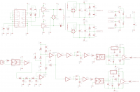
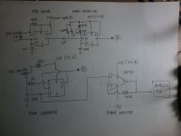
-(please see schem below(old), this is not very good design, but enough for my application, producing very linear ramp)
4. didn't use mica caps (just regular cheap MKP - no heating noticed @ 5pps for 3 min run)
5. I used single full-bridge fgh40n60smd (140 amp limit)
6. very high impedance of Primary of 80 ohms due to IGBT limitation
7. did use Eric's design buck control to produce ON interrupter pulse (going to UD) via comparator
I would like to mention some other sources i found over the net, maybe you could check their works too.
barmaley, bsvi, zrg, eric goodchild, cjk, & hvman. thanks to these guys though I was not able to talk with them even via mail :)
happy coiling! again thanks to your page! ;)


Re: Small QCW
teravolt, Wed Oct 08 2014, 01:34PM
hi loneoceans thanks for your work, I like your idea about a lower frequency secondary. how low in frequency can we go and still make sword sparks with a QCW
teravolt, Wed Oct 08 2014, 01:34PM
hi loneoceans thanks for your work, I like your idea about a lower frequency secondary. how low in frequency can we go and still make sword sparks with a QCW
Re: Small QCW
Steve Ward, Fri Oct 10 2014, 09:22PM
Its funny, i thought i used to know the recipe for making straight sparks, but it often eludes me on some designs.
In some cases i find the ramp needs to be very slow (long) for a coil to respond well. My newer tesla-gun designs seem to like 20+mS ramps for 5-6 foot straight sparks to form, but even then, MOST of the sparks are not without branches and bends. Ive had other designs that would make sparks in the 5-6 foot long range, with less ramp time (18mS or so), and had a much higher probability of growing without branches or bends. These setups always had bigger toroids.
Here i tried a bigger toroid (and removed the MMC from my secondary) on my gun V2 with good results. Not branchless, but really long and mostly straight:

However, nothing has compared to this experiment/result:

I suspect that the impedances and tuning of the coils plays a role in how much power is transfered to the spark as it grows over time and alters the tuning and losses of the system. My best results have always been achieved using larger 13-16" diameter toroids, and still keeping a high pole frequency of 400-450khz. These coils would shoot branchless sparks most reliably.
Steve Ward, Fri Oct 10 2014, 09:22PM
Its funny, i thought i used to know the recipe for making straight sparks, but it often eludes me on some designs.
In some cases i find the ramp needs to be very slow (long) for a coil to respond well. My newer tesla-gun designs seem to like 20+mS ramps for 5-6 foot straight sparks to form, but even then, MOST of the sparks are not without branches and bends. Ive had other designs that would make sparks in the 5-6 foot long range, with less ramp time (18mS or so), and had a much higher probability of growing without branches or bends. These setups always had bigger toroids.
Here i tried a bigger toroid (and removed the MMC from my secondary) on my gun V2 with good results. Not branchless, but really long and mostly straight:

However, nothing has compared to this experiment/result:

I suspect that the impedances and tuning of the coils plays a role in how much power is transfered to the spark as it grows over time and alters the tuning and losses of the system. My best results have always been achieved using larger 13-16" diameter toroids, and still keeping a high pole frequency of 400-450khz. These coils would shoot branchless sparks most reliably.
Re: Small QCW
zzz_julian_zzz, Sat Oct 11 2014, 12:57AM
Steve,

I am so wondering HOW you guys manage to get a low peak current on the primary given on that output length of about 6 ft?
my coil shoots a meter but having a 120+ Amps on the primary, i doubt that even when my Ipk reach 160 it will produce the same result as yours.
I've researched some russian QCW coils, and as expected, they need about 250-300 Amps to reach 6" sparks.
So what's your Magic steve? :)
May we know that coil's coupling?
Is it phase shifted shared bridge or DC modulated supply?
what's your Bridge's Voltage in?
That vid of yours freaks me out! :D
zzz_julian_zzz, Sat Oct 11 2014, 12:57AM
Steve,

I am so wondering HOW you guys manage to get a low peak current on the primary given on that output length of about 6 ft?
my coil shoots a meter but having a 120+ Amps on the primary, i doubt that even when my Ipk reach 160 it will produce the same result as yours.
I've researched some russian QCW coils, and as expected, they need about 250-300 Amps to reach 6" sparks.
So what's your Magic steve? :)
May we know that coil's coupling?
Is it phase shifted shared bridge or DC modulated supply?
what's your Bridge's Voltage in?
That vid of yours freaks me out! :D
Re: Small QCW
Uspring, Sat Oct 11 2014, 09:00AM
Steve Ward wrote:
Uspring, Sat Oct 11 2014, 09:00AM
Steve Ward wrote:
I suspect that the impedances and tuning of the coils plays a role in how much power is transfered to the spark as it grows over time and alters the tuning and losses of the system.Did you compare secondary voltage envelopes? The might differ from primary current shapes. My guess is, that arc style depends only on that and frequency.
Re: Small QCW
loneoceans, Sat Oct 11 2014, 04:13PM
I think the kind of tuning helps a lot here, i.e. the one Steve conner proposed to tune the primary lower and run at the upper pole frequency. As the spark drops the secondary resonant frequency, the coil becomes more and more in tune allowing the inverter to pump more power into the spark. This requires a different drive design though. The tesla gun uses the phase shifted method. It seems that BSVi's phase shifted coil does the same kind of tuning and has also achieved really long sparks (2m!) with not so much current.
loneoceans, Sat Oct 11 2014, 04:13PM
zzz_julian_zzz wrote ...
I am so wondering HOW you guys manage to get a low peak current on the primary given on that output length of about 6 ft?
my coil shoots a meter but having a 120+ Amps on the primary, i doubt that even when my Ipk reach 160 it will produce the same result as yours.
I've researched some russian QCW coils, and as expected, they need about 250-300 Amps to reach 6" sparks.
So what's your Magic steve? :)
May we know that coil's coupling?
Is it phase shifted shared bridge or DC modulated supply?
what's your Bridge's Voltage in?
I think the kind of tuning helps a lot here, i.e. the one Steve conner proposed to tune the primary lower and run at the upper pole frequency. As the spark drops the secondary resonant frequency, the coil becomes more and more in tune allowing the inverter to pump more power into the spark. This requires a different drive design though. The tesla gun uses the phase shifted method. It seems that BSVi's phase shifted coil does the same kind of tuning and has also achieved really long sparks (2m!) with not so much current.
Re: Small QCW
zzz_julian_zzz, Sun Oct 12 2014, 02:21PM
thanks loneoceans, hmmm.. these QCWs are getting more interesting than before, now that "finally" someone spoke up really helpful :)
so are you saying that in steve's video he uses Phase shifted topology and not the converter approach to get his primary current down? also, have you seen this vid?

this is a work of Barmaley (maybe he's a russian too) - i found that he's using a buck converter supply (sync buck) but he's just using a iron core for the Inductor Output of the Buck (Strange!) -this is a huge size iron cored inductor :) but as you can see, his works can be compared to other top QCW record holders :) this too works with smaller currents too..
zzz_julian_zzz, Sun Oct 12 2014, 02:21PM
loneoceans wrote ...
I think the kind of tuning helps a lot here, i.e. the one Steve conner proposed to tune the primary lower and run at the upper pole frequency. As the spark drops the secondary resonant frequency, the coil becomes more and more in tune allowing the inverter to pump more power into the spark. This requires a different drive design though. The tesla gun uses the phase shifted method. It seems that BSVi's phase shifted coil does the same kind of tuning and has also achieved really long sparks (2m!) with not so much current.
I think the kind of tuning helps a lot here, i.e. the one Steve conner proposed to tune the primary lower and run at the upper pole frequency. As the spark drops the secondary resonant frequency, the coil becomes more and more in tune allowing the inverter to pump more power into the spark. This requires a different drive design though. The tesla gun uses the phase shifted method. It seems that BSVi's phase shifted coil does the same kind of tuning and has also achieved really long sparks (2m!) with not so much current.
thanks loneoceans, hmmm.. these QCWs are getting more interesting than before, now that "finally" someone spoke up really helpful :)
so are you saying that in steve's video he uses Phase shifted topology and not the converter approach to get his primary current down? also, have you seen this vid?

this is a work of Barmaley (maybe he's a russian too) - i found that he's using a buck converter supply (sync buck) but he's just using a iron core for the Inductor Output of the Buck (Strange!) -this is a huge size iron cored inductor :) but as you can see, his works can be compared to other top QCW record holders :) this too works with smaller currents too..

Re: Small QCW
teravolt, Sun Oct 12 2014, 07:35PM
Julian I would think that iron would be a logical choice since the smps ramp is in the 20 ms range since iron has a response up to 400 hz. I have read in places like

and hear

that the L and C filter works by storing energy. I see that it pausible that the tesla converts this stored energy as it ramping up. A good choice would be to make your inductor with metglass because it has the highest permeability with a frequency response of 100kHz.

teravolt, Sun Oct 12 2014, 07:35PM
Julian I would think that iron would be a logical choice since the smps ramp is in the 20 ms range since iron has a response up to 400 hz. I have read in places like

and hear

that the L and C filter works by storing energy. I see that it pausible that the tesla converts this stored energy as it ramping up. A good choice would be to make your inductor with metglass because it has the highest permeability with a frequency response of 100kHz.

Re: Small QCW
zzz_julian_zzz, Mon Oct 13 2014, 10:59AM
Thanks for these information. Maybe we were just relying too much on the early/pioneer researchers, that only Ferrite Core would be the best and that suits for buck converters. Actually, I don't have that experience with regards to these core materials in SMPS topologies.
zzz_julian_zzz, Mon Oct 13 2014, 10:59AM
teravolt wrote ...
Julian I would think that iron would be a logical choice since the smps ramp is in the 20 ms range since iron has a response up to 400 hz. I have read in places like

and hear

that the L and C filter works by storing energy. I see that it pausible that the tesla converts this stored energy as it ramping up. A good choice would be to make your inductor with metglass because it has the highest permeability with a frequency response of 100kHz.

Julian I would think that iron would be a logical choice since the smps ramp is in the 20 ms range since iron has a response up to 400 hz. I have read in places like

and hear

that the L and C filter works by storing energy. I see that it pausible that the tesla converts this stored energy as it ramping up. A good choice would be to make your inductor with metglass because it has the highest permeability with a frequency response of 100kHz.

Thanks for these information. Maybe we were just relying too much on the early/pioneer researchers, that only Ferrite Core would be the best and that suits for buck converters. Actually, I don't have that experience with regards to these core materials in SMPS topologies.
Re: Small QCW
Steve Conner, Mon Oct 13 2014, 12:51PM
For the buck converter you need a powdered iron core, or MPP (Moly-Permalloy Powder, like deluxe powdered iron) or a ferrite core with an air gap. Ungapped ferrite is no good, and I doubt Metglass would be any good either. These are high permeability materials for transformers, they saturate too easily for an inductor that needs to store energy.
A laminated iron core with an air gap might well work, at least in Soviet Russia.

Re: Small QCW
Uspring, Mon Oct 13 2014, 04:08PM
a) Primary impedance. A larger impedance decreases primary I. You seem to have a large primary Z, so I don't think that's your particular problem.
b) Coupling, a higher coupling will also decrease current. Your coupling is also large (0.4?), so that's also not an issue.
c) Tuning, don't know waht your primary and secondary fres are, so it's hard to tell. But I guess you have played around with that.
d) Secondary Z. There is a sweet spot for secondary inductance. Both too low or too high will lead to a large primary I.
Check for secondary inductances of other successful builds.
Wrt to arc length:
a) Power, loneoceans coil currently has 150V and 120A (full bridge) input. Peak power is then 150*120*2*2/pi = 23kW. That's pretty much needed for 1m arcs.
b) Straight arcs, made with the right rampup are longer than short burst arcs. So the right current envelope will also increase length.
To diagnose the problem it would help to know primary and secondary tank parameters and a scope shot of primary current and secondary voltage (picked up with an antenna).
Uspring, Mon Oct 13 2014, 04:08PM
I am so wondering HOW you guys manage to get a low peak current on the primary given on that output length of about 6 ft?There are a number of factors which influence primary current:
a) Primary impedance. A larger impedance decreases primary I. You seem to have a large primary Z, so I don't think that's your particular problem.
b) Coupling, a higher coupling will also decrease current. Your coupling is also large (0.4?), so that's also not an issue.
c) Tuning, don't know waht your primary and secondary fres are, so it's hard to tell. But I guess you have played around with that.
d) Secondary Z. There is a sweet spot for secondary inductance. Both too low or too high will lead to a large primary I.
Check for secondary inductances of other successful builds.
Wrt to arc length:
a) Power, loneoceans coil currently has 150V and 120A (full bridge) input. Peak power is then 150*120*2*2/pi = 23kW. That's pretty much needed for 1m arcs.
b) Straight arcs, made with the right rampup are longer than short burst arcs. So the right current envelope will also increase length.
To diagnose the problem it would help to know primary and secondary tank parameters and a scope shot of primary current and secondary voltage (picked up with an antenna).
Re: Small QCW
zzz_julian_zzz, Tue Oct 14 2014, 05:06AM
Hi upspring,
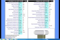
thank you very much for your comments, by the way, here are my coil's specifications and output from JAVATC.
I don't know too if the Impedance/Inductance of my Secondary is not in "good shape" to get swordish sparks.

zzz_julian_zzz, Tue Oct 14 2014, 05:06AM
Uspring wrote ...
a) Primary impedance. A larger impedance decreases primary I. You seem to have a large primary Z, so I don't think that's your particular problem.
b) Coupling, a higher coupling will also decrease current. Your coupling is also large (0.4?), so that's also not an issue.
c) Tuning, don't know waht your primary and secondary fres are, so it's hard to tell. But I guess you have played around with that.
d) Secondary Z. There is a sweet spot for secondary inductance. Both too low or too high will lead to a large primary I.
Check for secondary inductances of other successful builds.
Wrt to arc length:
a) Power, loneoceans coil currently has 150V and 120A (full bridge) input. Peak power is then 150*120*2*2/pi = 23kW. That's pretty much needed for 1m arcs.
b) Straight arcs, made with the right rampup are longer than short burst arcs. So the right current envelope will also increase length.
To diagnose the problem it would help to know primary and secondary tank parameters and a scope shot of primary current and secondary voltage (picked up with an antenna).
I am so wondering HOW you guys manage to get a low peak current on the primary given on that output length of about 6 ft?There are a number of factors which influence primary current:
a) Primary impedance. A larger impedance decreases primary I. You seem to have a large primary Z, so I don't think that's your particular problem.
b) Coupling, a higher coupling will also decrease current. Your coupling is also large (0.4?), so that's also not an issue.
c) Tuning, don't know waht your primary and secondary fres are, so it's hard to tell. But I guess you have played around with that.
d) Secondary Z. There is a sweet spot for secondary inductance. Both too low or too high will lead to a large primary I.
Check for secondary inductances of other successful builds.
Wrt to arc length:
a) Power, loneoceans coil currently has 150V and 120A (full bridge) input. Peak power is then 150*120*2*2/pi = 23kW. That's pretty much needed for 1m arcs.
b) Straight arcs, made with the right rampup are longer than short burst arcs. So the right current envelope will also increase length.
To diagnose the problem it would help to know primary and secondary tank parameters and a scope shot of primary current and secondary voltage (picked up with an antenna).
Hi upspring,
thank you very much for your comments, by the way, here are my coil's specifications and output from JAVATC.
I don't know too if the Impedance/Inductance of my Secondary is not in "good shape" to get swordish sparks.


Re: Small QCW
Dr. Dark Current, Tue Oct 14 2014, 07:22AM
I think its just Vout*Ipk*2/pi, so 11.5 kW in this case.
Dr. Dark Current, Tue Oct 14 2014, 07:22AM
Uspring wrote ...
Wrt to arc length:
a) Power, loneoceans coil currently has 150V and 120A (full bridge) input. Peak power is then 150*120*2*2/pi = 23kW. That's pretty much needed for 1m arcs.
Wrt to arc length:
a) Power, loneoceans coil currently has 150V and 120A (full bridge) input. Peak power is then 150*120*2*2/pi = 23kW. That's pretty much needed for 1m arcs.
I think its just Vout*Ipk*2/pi, so 11.5 kW in this case.
Re: Small QCW
Uspring, Tue Oct 14 2014, 10:30AM
zzz_julian_zzz:
Your secondary specs look reasonable. It'd be nice to compare them to loneoceans, but I couldn't find them in his writeup. What does your primary current rampup look like?
Dr. Dark Current:
Uspring, Tue Oct 14 2014, 10:30AM
zzz_julian_zzz:
Your secondary specs look reasonable. It'd be nice to compare them to loneoceans, but I couldn't find them in his writeup. What does your primary current rampup look like?
Dr. Dark Current:
I think its just Vout*Ipk*2/pi, so 11.5 kW in this case.I was under the impression, that he switches between +150 and -150V with a full bridge, i.e. an effective input voltage of 300V. (?)
Re: Small QCW
zzz_julian_zzz, Tue Oct 14 2014, 11:12AM
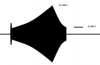
hi Upspring this is what it looks like when i try to scope my Pri I. Thank you.
zzz_julian_zzz, Tue Oct 14 2014, 11:12AM
hi Upspring this is what it looks like when i try to scope my Pri I. Thank you.

Re: Small QCW
Dr. Dark Current, Tue Oct 14 2014, 06:03PM
Udo, the output is just 150V, at one instant positive, at the other negative. The output voltage from a full bridge is the same as DC link voltage, with a half bridge it is half.
Dr. Dark Current, Tue Oct 14 2014, 06:03PM
Udo, the output is just 150V, at one instant positive, at the other negative. The output voltage from a full bridge is the same as DC link voltage, with a half bridge it is half.
Re: Small QCW
Uspring, Tue Oct 14 2014, 06:32PM
zzz_julian_zzz:
Looks ok to me, except for the current burst at the beginning. That might jump start the arc instead of growing it slowly. I don't think it explains large primary currents but possibly not so straight and long arcs. Possibly the bus voltage is too high, when you turn the interrupter on.
Dr. Dark Current:
Ok, you're thinking of a single +150V DC supply and I was thinking about a dual one, i.e. +150V and -150V.
Re: Small QCW
teravolt, Tue Oct 14 2014, 07:41PM
Hi Julian nice wave form. if you are using a half wave doubler from the line and your reference connection is the center of the caps it will never be more than 150v but you could play games like connecting it to a boost transformer or connect it to 220. I herd Steve Ward say that the power factor is better with full wave rectification with filter caps.
Re: Small QCW
Dr. Dark Current, Tue Oct 14 2014, 09:44PM
Well that could be it... but if someone says xxxV input, I automatically assume that its xxxV between the dc bus rails
Dr. Dark Current, Tue Oct 14 2014, 09:44PM
Well that could be it... but if someone says xxxV input, I automatically assume that its xxxV between the dc bus rails

Re: Small QCW
loneoceans, Sun May 24 2015, 07:56AM
It has been several months since I worked on my QCW.
Started to get busy with other things and new projects, including getting sidetracked on a pair of reasonably sized DRSSTCS (see project here , but I thought it was time to continue tinkering on the small QCW. Since then I've had a few ideas I wanted to try out while still keeping the coil the same. I finally got around to start putting things together.
This revision (I'm calling it v1.5) includes a fancy Bluetooth controller. I did it mostly for fun since I thought it was a bit gimmicky, but it turned out to be very useful indeed! So I can now use my phone to control the coil from a safe distance and not have to carry around a controller anymore. Also, I've upgraded the bus modulator to using a brick IGBT, and I've lowered the resonant frequency by 100kHz (but still using a 6" secondary), so it now oscillates around 360kHz on the upper pole.
Here's a very early test of the coil in action. I've got the ramp going to just over 200V for about 10ms and it's making around 4+ feet of spark to air. In this test the coil resonates at 360kHz to 340kHz with the buck switching frequency of around 8.5 to 20kHz. Each pulse here is just about 75J.
Here's a video of the coil in action together with the temporary setup!
One thing I noticed with this setup compared to my v1.0 was that the sparks were more knarly. This could also be due to the lower switching frequency where higher frequencies seem to produce straighter sparks; also my toroid is pretty small (8x2") - a bigger one might be better in directing sparks.
Right now have a few ideas in continuing to push the coil to make straighter sparks. For example, a bigger toroid, a higher impedance primary or one with higher coupling, as well as perhaps faster buck switching for a smoother ramp (which may be causing the sparks to break up) and a longer ramp duration.
The next step is of course, to step up the voltage! More to come soon and would appreciate any comments and suggestions!
loneoceans, Sun May 24 2015, 07:56AM
It has been several months since I worked on my QCW.

Started to get busy with other things and new projects, including getting sidetracked on a pair of reasonably sized DRSSTCS (see project here
 , but I thought it was time to continue tinkering on the small QCW. Since then I've had a few ideas I wanted to try out while still keeping the coil the same. I finally got around to start putting things together.
 This revision (I'm calling it v1.5) includes a fancy Bluetooth controller. I did it mostly for fun since I thought it was a bit gimmicky, but it turned out to be very useful indeed! So I can now use my phone to control the coil from a safe distance and not have to carry around a controller anymore. Also, I've upgraded the bus modulator to using a brick IGBT, and I've lowered the resonant frequency by 100kHz (but still using a 6" secondary), so it now oscillates around 360kHz on the upper pole.
Here's a very early test of the coil in action. I've got the ramp going to just over 200V for about 10ms and it's making around 4+ feet of spark to air. In this test the coil resonates at 360kHz to 340kHz with the buck switching frequency of around 8.5 to 20kHz. Each pulse here is just about 75J.
Here's a video of the coil in action together with the temporary setup!
One thing I noticed with this setup compared to my v1.0 was that the sparks were more knarly. This could also be due to the lower switching frequency where higher frequencies seem to produce straighter sparks; also my toroid is pretty small (8x2") - a bigger one might be better in directing sparks.
Right now have a few ideas in continuing to push the coil to make straighter sparks. For example, a bigger toroid, a higher impedance primary or one with higher coupling, as well as perhaps faster buck switching for a smoother ramp (which may be causing the sparks to break up) and a longer ramp duration.
The next step is of course, to step up the voltage! More to come soon and would appreciate any comments and suggestions!

Re: Small QCW
zzz_julian_zzz, Sun May 24 2015, 02:20PM
Hi loneoceans,
great development! The bluetooth interface made this coil astoundingly controllable 😄
is the signal all the same? In terms of magnitude and length?
I emailed you on your gmail, waiting for your response. 😄
zzz_julian_zzz, Sun May 24 2015, 02:20PM
Hi loneoceans,
great development! The bluetooth interface made this coil astoundingly controllable 😄
is the signal all the same? In terms of magnitude and length?
I emailed you on your gmail, waiting for your response. 😄
Re: Small QCW
loneoceans, Sun May 24 2015, 09:30PM
Right now I'm running just about a 10ms pulse with a ramp peak of about 200V. I didn't receive a mail from you though, are you sure you sent it to the right place?
There's still a bunch of tidying up I need to do - the wires are all over the place and are quite messy, so I'll be tidying it up. Next step is to do some tuning to see what I can get out of this coil
loneoceans, Sun May 24 2015, 09:30PM
zzz_julian_zzz wrote ...
Hi loneoceans,
great development! The bluetooth interface made this coil astoundingly controllable 😄
is the signal all the same? In terms of magnitude and length?
I emailed you on your gmail, waiting for your response. 😄
Hi loneoceans,
great development! The bluetooth interface made this coil astoundingly controllable 😄
is the signal all the same? In terms of magnitude and length?
I emailed you on your gmail, waiting for your response. 😄
Right now I'm running just about a 10ms pulse with a ramp peak of about 200V. I didn't receive a mail from you though, are you sure you sent it to the right place?
There's still a bunch of tidying up I need to do - the wires are all over the place and are quite messy, so I'll be tidying it up. Next step is to do some tuning to see what I can get out of this coil

Re: Small QCW
loneoceans, Thu Jun 04 2015, 05:55PM
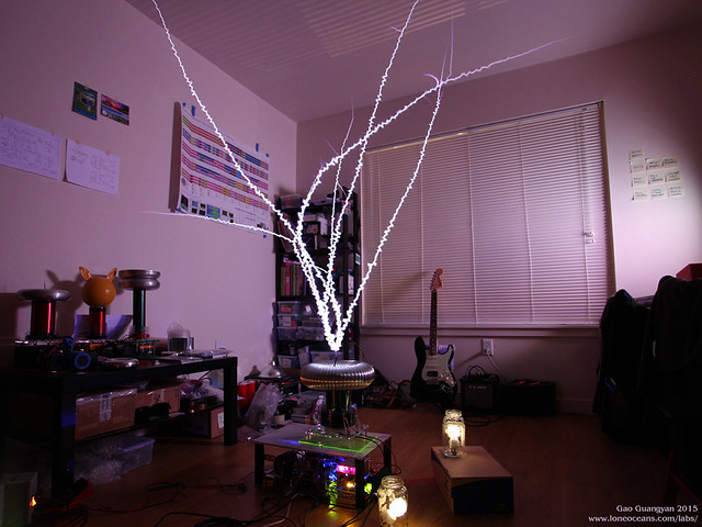
I thought I’d continue to update with some new results from the small QCW project. As always, been trying new things as I figure out what works. I’ve also since made a simple box case for the coil so I can move everything around easily, and have also been experimenting new ‘FAT TOROID’ for the coil .
.
After discussing with uspring and many other more experienced coilers than I am, I had a few new ideas to try out with the coil. Based on the measured results from the coil so far, it seems that my first few setups had a poor impedance match resulting in less than ideal power transfer. Consequently I had relatively high current in my primary circuit. Two main issues which seem to affect this the most are arc loading and coupling. With my small toroid, heavy arc loading caused significant detuning of my secondary circuit, which decreased Qpri leading to a lower effective load on the inverter side. There are other ways to achieve a similar effect, e.g. increasing primary impedance. However, I wanted to use the same MMC I had and I was running out of turns on my primary coil, so I made a new resonator setup. To summarize, I there exists an ideal effective impedance which the coil should be set to limit the maximum current just below the OCD limit at the peak of the ramp.
The new “Fat Toroid†setup uses my original 5.5†secondary with the new toroid made out of 3†aluminum ducting (it’s actually closer to 3.4†in diameter though). This gave me a resonant frequency of around 330kHz. I also made a new higher coupling primary with a k around 0.39, and tapped such that the coil has an upper pole around 420kHz. With a maximum of 400V on my bus (limited by my variac and my 400V bus cap), I designed the setup to run with a ~300++V peak ramp to hit a 150A limit. This paid off with just over 5 feet of spark (measured around 11.5x secondary length), at a ~310V peak at around 150+A as designed.
loneoceans, Thu Jun 04 2015, 05:55PM

I thought I’d continue to update with some new results from the small QCW project. As always, been trying new things as I figure out what works. I’ve also since made a simple box case for the coil so I can move everything around easily, and have also been experimenting new ‘FAT TOROID’ for the coil
 .
.After discussing with uspring and many other more experienced coilers than I am, I had a few new ideas to try out with the coil. Based on the measured results from the coil so far, it seems that my first few setups had a poor impedance match resulting in less than ideal power transfer. Consequently I had relatively high current in my primary circuit. Two main issues which seem to affect this the most are arc loading and coupling. With my small toroid, heavy arc loading caused significant detuning of my secondary circuit, which decreased Qpri leading to a lower effective load on the inverter side. There are other ways to achieve a similar effect, e.g. increasing primary impedance. However, I wanted to use the same MMC I had and I was running out of turns on my primary coil, so I made a new resonator setup. To summarize, I there exists an ideal effective impedance which the coil should be set to limit the maximum current just below the OCD limit at the peak of the ramp.
The new “Fat Toroid†setup uses my original 5.5†secondary with the new toroid made out of 3†aluminum ducting (it’s actually closer to 3.4†in diameter though). This gave me a resonant frequency of around 330kHz. I also made a new higher coupling primary with a k around 0.39, and tapped such that the coil has an upper pole around 420kHz. With a maximum of 400V on my bus (limited by my variac and my 400V bus cap), I designed the setup to run with a ~300++V peak ramp to hit a 150A limit. This paid off with just over 5 feet of spark (measured around 11.5x secondary length), at a ~310V peak at around 150+A as designed.
Re: Small QCW
zzz_julian_zzz, Fri Jun 05 2015, 12:36PM
HOLY COW! this is impressive ! :D nice work! could you share your way on how to measure impedance (Pri-Sec) and how to match them properly ? :)
zzz_julian_zzz, Fri Jun 05 2015, 12:36PM
loneoceans wrote ...

I thought I’d continue to update with some new results from the small QCW project. As always, been trying new things as I figure out what works. I’ve also since made a simple box case for the coil so I can move everything around easily, and have also been experimenting new ‘FAT TOROID’ for the coil .
.
After discussing with uspring and many other more experienced coilers than I am, I had a few new ideas to try out with the coil. Based on the measured results from the coil so far, it seems that my first few setups had a poor impedance match resulting in less than ideal power transfer. Consequently I had relatively high current in my primary circuit. Two main issues which seem to affect this the most are arc loading and coupling. With my small toroid, heavy arc loading caused significant detuning of my secondary circuit, which decreased Qpri leading to a lower effective load on the inverter side. There are other ways to achieve a similar effect, e.g. increasing primary impedance. However, I wanted to use the same MMC I had and I was running out of turns on my primary coil, so I made a new resonator setup. To summarize, I there exists an ideal effective impedance which the coil should be set to limit the maximum current just below the OCD limit at the peak of the ramp.
The new “Fat Toroid†setup uses my original 5.5†secondary with the new toroid made out of 3†aluminum ducting (it’s actually closer to 3.4†in diameter though). This gave me a resonant frequency of around 330kHz. I also made a new higher coupling primary with a k around 0.39, and tapped such that the coil has an upper pole around 420kHz. With a maximum of 400V on my bus (limited by my variac and my 400V bus cap), I designed the setup to run with a ~300++V peak ramp to hit a 150A limit. This paid off with just over 5 feet of spark (measured around 11.5x secondary length), at a ~310V peak at around 150+A as designed.

I thought I’d continue to update with some new results from the small QCW project. As always, been trying new things as I figure out what works. I’ve also since made a simple box case for the coil so I can move everything around easily, and have also been experimenting new ‘FAT TOROID’ for the coil
 .
.After discussing with uspring and many other more experienced coilers than I am, I had a few new ideas to try out with the coil. Based on the measured results from the coil so far, it seems that my first few setups had a poor impedance match resulting in less than ideal power transfer. Consequently I had relatively high current in my primary circuit. Two main issues which seem to affect this the most are arc loading and coupling. With my small toroid, heavy arc loading caused significant detuning of my secondary circuit, which decreased Qpri leading to a lower effective load on the inverter side. There are other ways to achieve a similar effect, e.g. increasing primary impedance. However, I wanted to use the same MMC I had and I was running out of turns on my primary coil, so I made a new resonator setup. To summarize, I there exists an ideal effective impedance which the coil should be set to limit the maximum current just below the OCD limit at the peak of the ramp.
The new “Fat Toroid†setup uses my original 5.5†secondary with the new toroid made out of 3†aluminum ducting (it’s actually closer to 3.4†in diameter though). This gave me a resonant frequency of around 330kHz. I also made a new higher coupling primary with a k around 0.39, and tapped such that the coil has an upper pole around 420kHz. With a maximum of 400V on my bus (limited by my variac and my 400V bus cap), I designed the setup to run with a ~300++V peak ramp to hit a 150A limit. This paid off with just over 5 feet of spark (measured around 11.5x secondary length), at a ~310V peak at around 150+A as designed.
HOLY COW! this is impressive ! :D nice work! could you share your way on how to measure impedance (Pri-Sec) and how to match them properly ? :)
Re: Small QCW
Intra, Fri Jun 05 2015, 03:33PM
Hi Gao,
Did you played some music through your QCW? does your buck-modulator and interrupter allows playing music?
Intra, Fri Jun 05 2015, 03:33PM
Hi Gao,
Did you played some music through your QCW? does your buck-modulator and interrupter allows playing music?
Re: Small QCW
Aragorn, Sun Jun 07 2015, 09:14AM
I would have thought the on-times were too long to create DRSSTC style music when in QCW mode.
Each bang is 10ms long vs say 100us in a DR?
Aragorn, Sun Jun 07 2015, 09:14AM
I would have thought the on-times were too long to create DRSSTC style music when in QCW mode.
Each bang is 10ms long vs say 100us in a DR?
Re: Small QCW
loneoceans, Sun Jun 07 2015, 07:25PM
I haven't made a music controller made for the QCW but the modulator accepts any sort of signal input, so yes should have no problems playing most sorts of music. Would probably work great with the bass notes :)
loneoceans, Sun Jun 07 2015, 07:25PM
Intra wrote ...
Hi Gao,
Did you played some music through your QCW? does your buck-modulator and interrupter allows playing music?
Hi Gao,
Did you played some music through your QCW? does your buck-modulator and interrupter allows playing music?
I haven't made a music controller made for the QCW but the modulator accepts any sort of signal input, so yes should have no problems playing most sorts of music. Would probably work great with the bass notes :)
Re: Small QCW
loneoceans, Mon Jun 15 2015, 08:03PM
Alright I think performance for this coil is more or less near what it can do for now :). Here are the results:
- Spark length just over 70" to air!
- Secondary coil winding: 5.5" with FAT TOROID
- Primary Current 145 to 160A depending on spark
I'm also running out of bus capacitance, so I'm limited to a ramp of just over 300V with 400V on the bus. Here are some photos for your enjoyment:
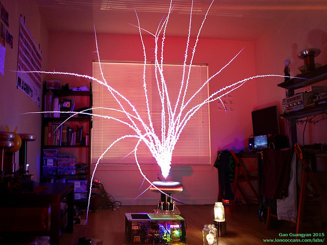
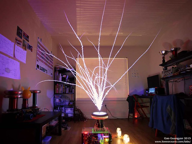
I also tidied up everything into a reasonably compact box so now it's not just a mess of wires on the floor.
loneoceans, Mon Jun 15 2015, 08:03PM
Alright I think performance for this coil is more or less near what it can do for now :). Here are the results:
- Spark length just over 70" to air!
- Secondary coil winding: 5.5" with FAT TOROID
- Primary Current 145 to 160A depending on spark
I'm also running out of bus capacitance, so I'm limited to a ramp of just over 300V with 400V on the bus. Here are some photos for your enjoyment:


I also tidied up everything into a reasonably compact box so now it's not just a mess of wires on the floor.

Re: Small QCW
Justin, Mon Jun 15 2015, 11:23PM
Wow, that's a great shot. It's amusing to see these enormous sparks coming from a tiny secondary. High speed footage of the spark formation would be great.
Justin, Mon Jun 15 2015, 11:23PM
Wow, that's a great shot. It's amusing to see these enormous sparks coming from a tiny secondary. High speed footage of the spark formation would be great.
Re: Small QCW
kilovolt, Tue Jun 16 2015, 11:28AM
Very amazing results, loneoceans! Really great work Thanks for posting the pics and the docu of your work.
Best regards
kilovolt
kilovolt, Tue Jun 16 2015, 11:28AM
Very amazing results, loneoceans! Really great work
 Thanks for posting the pics and the docu of your work.
Best regards
kilovolt
Re: Small QCW
zzz_julian_zzz, Tue Jun 16 2015, 11:37AM
WOW! :D cool results Guangyan!
zzz_julian_zzz, Tue Jun 16 2015, 11:37AM
WOW! :D cool results Guangyan!
Re: Small QCW
loneoceans, Sat Jun 27 2015, 08:04PM
I did a write-up on this coil. Hopefully it'll be useful to everyone! Still working through it, so let me know if there are any mistakes.
QCW 1.5 Writeup page:
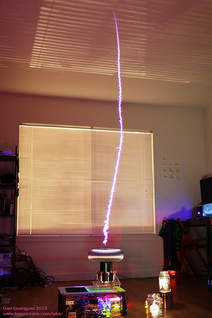
I managed to get a lucky single shot photo which shows the spark climbing up very straight.
loneoceans, Sat Jun 27 2015, 08:04PM
I did a write-up on this coil. Hopefully it'll be useful to everyone! Still working through it, so let me know if there are any mistakes.
QCW 1.5 Writeup page:


I managed to get a lucky single shot photo which shows the spark climbing up very straight.
Re: Small QCW
zzz_julian_zzz, Sun Jun 28 2015, 12:11AM
Hi Guangyan,
Thanks for this wonderful documentation :) Hope this helps with other QCW triers around the net :) really great page indeed!
zzz_julian_zzz, Sun Jun 28 2015, 12:11AM
Hi Guangyan,
Thanks for this wonderful documentation :) Hope this helps with other QCW triers around the net :) really great page indeed!
Re: Small QCW
RateReducer, Sun Jun 28 2015, 04:30PM
Wow this is really cool stuff!
So the bigger topload increased streamer length?
I also wanted to try that but unfortunately i killed my QCW coil some time ago -__- Did not try to much to bring it back to live since then... Need to do that in the near future! I just tried a different primary tap to see if it increases streamer length. After a few bursts the coil died quiet and the electrolytic caps in the buck stayed charged so i guess the bridge and the buck are still alive.
RateReducer, Sun Jun 28 2015, 04:30PM
Wow this is really cool stuff!

So the bigger topload increased streamer length?
I also wanted to try that but unfortunately i killed my QCW coil some time ago -__- Did not try to much to bring it back to live since then... Need to do that in the near future! I just tried a different primary tap to see if it increases streamer length. After a few bursts the coil died quiet and the electrolytic caps in the buck stayed charged so i guess the bridge and the buck are still alive.
Re: Small QCW
omegalabs, Thu Jul 02 2015, 09:55AM
Looks really nice.
Looking at these highly coupled coils, isn't it possible to build a QCW magnifier and make the coupling even higher and a smoother E field without the danger of a flashover?
omegalabs, Thu Jul 02 2015, 09:55AM
Looks really nice.
Looking at these highly coupled coils, isn't it possible to build a QCW magnifier and make the coupling even higher and a smoother E field without the danger of a flashover?
Re: Small QCW
zzz_julian_zzz, Wed Jul 08 2015, 12:44AM
Hi Guangyan,
Just wanted to share, if it will be of any help to others, that your conclusion for spark length somewhat relates to my experiments as well...
1. i.e. 1 cm is roughly 1 Amp so 130cm is 130 Amp
2. Spark length below reaches about 50 inch (4x6" sec coil, with toroid 13.35") with about 125-130 Amps in the Primary. Sec Fres around 360khz (uncoupled) 325 (coupled k=0.4 to Primary) Primary resonates 400 khz (Upper) and drops around 369 khz at the peak of the ramp. (hmmm... Pri fres is low I think?)
3. Found out that the key for very low Pri current is to keep very high Coupling factor. From JAVATC, my QC is set (0.4), ARCING is really a problem here! I put a lot rubbers around the secondary coil haha! :D it looks nasty but it's okay as long as the insulation does its job.
4. Keep Zurge impedance high, mine hits 41.3 ohms.. i.e. 20uH and a 11.75nf pri cap (uncoupled freq is 310khz)
5. Increase Bus Voltage, Instead of Ramp length.. (my current Ramp set up is @ 8ms/with 4ms down)
I think I can even increase the spark length by just increasing the bus voltage. Now, the V peak is at 328volts. My max Voltage is 450v (18mf/450v DC cap) I am using a boost converter to charge this cap to 430v. With the loading, Peak V can be adjusted and reach up to 420 volts. (90v higher than the previous). Problem here is that I am only using a single full-bridge of FGA60N65SMD (Rjc of 0.25 / 650vdc) I think its max duty for QCW operation can be at 220 Amps (IRGP50B60PD1 Rjc of 0.32/600v is at 200 Amps) but I don't want to test this limit :) instead, I'll be using parallel bridge. And probably add another 10mf/450v DC caps so to help with regulation. Will post the result after I change the bridge.
Question: after doing parallel bridge, do I still need to undergo phase lead tuning? arggg! consumes my time a lot! :(
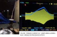

Print this page