
Novice-Built Induction Heater (In 14 days?)
AwesomeMatt, Fri Aug 22 2014, 04:25AMHey everyone,
I'm going to try to build a 6kW induction heater in a couple weeks, without much knowledge. I could really use some help.
I've been wanting to build an induction heater for a couple years for my local hackerspace. It was just never worth the personal investment. Well, I got funding from a small arts grant (a couple hundred bucks). I'm building it and then I'm donating it for everyone to use.
Caveat - I should have it ready for our local mini Makerfaire which is in... 14 days. (I have lots of free time in these next 2 weeks).
I'm a complete novice but I've been doing a lot of reading the last couple weeks. I've somewhat stopped progressing. Most explanations answer my questions in ways I don't understand, I might need it dumbed down more.
Specs:
- Should be able to do molten aluminum levitation demos at events (oooh, ahhh).
- Will be used for casting/forging projects the rest of the year.
- Needs to run on 120v (for events)
- Should run on 240v (back at the 'space, err, actually 208v since it's 2 arms of 3-phase).
- I'm targeting 30A @ 208V, so... ~6,000W.
I have not settled on a design, much, except that it'll be series-resonant.
I understand some of the big pieces of the circuit, but not others. I have seen IAMSMOOTH's tutorial
 , but it doesn't entirely make sense to me. I have read through some other induction heating projects on 4HV too.
I try my best when soliciting advice from the community to at least well-document my project with photos and video on the fly, and (eventually) tutorials later.
Resources/What I Understand:
- Ohm's law, Power law, Kirchoff's laws.
- I have access to lots of scopes & signal gens, but I haven't used them in years (rusty but capable).
- Huge assortment of general parts (resistors, caps, regulators).
- Fairly good access to scrap electronics (have salvaged/stripped a bunch over the years).
- A year's worth of school study for C++/Java/etc. I can understand and modify other's code, but probably not write anything from scratch.
What I Need Help With:
- Parts list!! - Before I even understand what I'm doing, I kinda need to go go go go go, as the fancy parts have to be shipped ASAP (I'm in Canada).
- Parts shopping - I've always just scavenged parts, so I'm not all that familiar with "Oh, you'd want to buy this from here" or actually searching for the right part or specs.
- Explain like I'm 5 years old the basic building blocks of the circuit. - Higher-level explanations are common, but they don't quite sink in enough for me to solve my own problems.
- Arduino stuff - I would like it to be auto-tuning, I've been meaning to tinker with micros for years but haven't.
Plan/Progress So Far:
- Settled on series-resonant
- 10x 1.25uF, 600vac 46A (each) tank caps (to be put in parallel)... if they'll ship them to Canada... in time.
- ~15khz resonance (??? ish ??? does that sound right?)
- I have 1/4" copper tubing
- I have a few square feet of double-sided circuitboard blank (I have both CNC mill & etching equipment).
- I have a couple small radiators and/or a couple really big buckets
- I have sheet metal/acrylic for enclosure
- I have a big beefy 50A rectifier
- I have plenty electrolytics to smooth the wall voltage to ~300VDC (or 170VDC on a 120v circuit).
- I have lots of heatsinks
- Tracking down sources for several large ferrite torroids (probably good there)
- I want a micro controller to auto-tune, Arduino or otherwise, I don't care, but I'm a complete novice.
- I need a "buck converter" (?) to drop the voltage down, as my power control method. I know what this is, I don't know where to start building one to these specs.
- I'll use an H-bridge to control the inverting (I only vaguely understand these)
- I need an H-bridge driver of some sort?
- IGBTs for something?
The closer to output the more I understand. Rectified and smoothed line voltage I understand. But the closer to the input the fuzzier and fuzzier I get as to what controls what and what's happening and why and what parts I would need.
...
So, ASAP, I'd like to order any obscure parts that I will obviously need. I think I need at least a couple 600V half-bridge drivers (?) and some (?) 500V MOSFETS? I don't know how to shop for these, I feel like I'm reading ingredient labels for a language I don't speak.
Anything else that I wouldn't have in a basics electronic kit or from salvaging CRT/PSU/VCR/Etc boards for a few years?
Any advice, explanations, narrowing-downs or criticism very much appreciated.
Thanks in advance everyone who helps me tackle this. Again, I'm immediately donating it to the local maker community.
Re: Novice-Built Induction Heater (In 14 days?)
Dago, Fri Aug 22 2014, 05:09AM
I honestly doubt you will make it. Even if you'd know 100% what you're doing and have everything you need at hand you'd still have a hell of a hurry in two weeks. Even ordering something will take several days and you'd need to figure out the design before you order anything.
Re: Novice-Built Induction Heater (In 14 days?)
Sigurthr, Fri Aug 22 2014, 05:32AM
I echo the above. The planning and build time alone (never mind troubleshooting) is considerable.
Pit falls to watch out for: series resonant will result in the driver overloading when no load is present. Unlike in parallel resonant where you can get away with no OCD protection, it isn't an option for series resonant. You'll also need to keep the inverter at resonance or above resonance (inductive region) - inverters do NOT like being run in the capacitive region.
Think of it as a DRSSTC with the secondary removed, this will help you realize the control schemes and basic processes you're working with.
Most use a PLL and not a uC. I think it can be done on a uC, at least for the current monitoring part, but that's like using a pneumatic press for a hammer to hang a picture in drywall. Arduino's aren't good at precise timing above a few kHz. I've done several projects where I've pushed the boundaries a bit and gotten good results, but all of the ones what worked involved fixed frequency output at a frequency the arduino was happy with. Getting continuous frequency range and accuracy isn't something arduinos are good at.
Designing a buck converter capable of 6kW is a HUUUUUGE project alone. Think you may have bitten off too much here.
Re: Novice-Built Induction Heater (In 14 days?)
Dago, Fri Aug 22 2014, 06:19AM
I'm currently building an induction heater myself and I've already spent quite a lot of time (months, not continuous time though) just getting the (digital) control loop to work as it should ( ). And it's still lacking in features such as adjustable phase difference and detuning. Though I did kinda spend a lot of time making a VHDL version as well at the same time:
  (haven't posted anything about it yet). I think it might be possible to use an arduino for that if you divide the feedback frequency down but not really that optimal. I used an STM32 ARM myself.
Dago, Fri Aug 22 2014, 06:19AM
I'm currently building an induction heater myself and I've already spent quite a lot of time (months, not continuous time though) just getting the (digital) control loop to work as it should (
 ). And it's still lacking in features such as adjustable phase difference and detuning. Though I did kinda spend a lot of time making a VHDL version as well at the same time:
  (haven't posted anything about it yet). I think it might be possible to use an arduino for that if you divide the feedback frequency down but not really that optimal. I used an STM32 ARM myself.
Re: Novice-Built Induction Heater (In 14 days?)
AwesomeMatt, Fri Aug 22 2014, 08:06AM
I know it's ambitious. There was hubris in me thinking "Well, I've seen a handful of people make these before. I'll just pick one from plans and build it."
Except, everyone's is different and everyone's is for slightly different things.
I do have local help, but everyone's busy with their own Makerfaire projects and can't help design until... it's too late for me to start planning.
My backup plan is the quick 'n dirty parallel resonant heater (a couple/few hundred watts) for the faire, and build the big one later. But I figure I can slap one of those together in a few hours.
I know it probably won't do levitation, even of tiny aluminum cutoffs, but, at least it'll show heating.
As to the Arduino, that's what IAMSMOOTH does on his big 10kw unit and suggests doing. I'm probably more comfortable tinkering with code than I am bumbling through analog electronics. I don't care if it's overkill, if it means I get it done sooner, can tweak it more easily, and it's more robust.
Build-time does not concern me. I can throw 15 hours a day at it. "I don't know where to start" time worries me. That, and the later "I don't know how to solve this" time.
Either way, I'm proceeding.
Re: Novice-Built Induction Heater (In 14 days?)
Steve Conner, Fri Aug 22 2014, 08:25AM
A good starting point would be a series resonant heater with the Uzzors PLL driver circuit. Check out the "OMG Induction Heater" thread on here for a good run down of what various people have built.
For the power levels you're planning, and especially for levitation you will need a water-cooled coil and some really good capacitors, also with water cooling. The capacitors are far and away the most important thing, the details of the driver hardly matter in comparison.
Steve Conner, Fri Aug 22 2014, 08:25AM
A good starting point would be a series resonant heater with the Uzzors PLL driver circuit.
 Check out the "OMG Induction Heater" thread on here for a good run down of what various people have built.
For the power levels you're planning, and especially for levitation you will need a water-cooled coil and some really good capacitors, also with water cooling. The capacitors are far and away the most important thing, the details of the driver hardly matter in comparison.
Re: Novice-Built Induction Heater (In 14 days?)
AwesomeMatt, Fri Aug 22 2014, 08:47AM
I've already read through this a couple times, but, lacking context, was not sure if it was acceptable for my use.
Looks good, I'll read it again and probably just copy it outright if that's your suggestion.
Yes, the tank capacitors are what I've been spending most of my time on. I think I have that nailed down, *IF* they'll ship the ones I want to Canada.
1.25uF, 600VAC, 46amps continuous... and I'll take 10 of those in parallel.
I'm aware of water cooling requirements (and low-inductance pathing for the caps) and have that planned out.
It's more, the big gap between "Rectified & Smoothed 300VDC" and "Coupling transformer/Output Coil". All the H-bridge, half-bridge, PLL... I don't even understand what all those circuits are or how they work (in a macro sense).
I could really use a dumbed down ABC of what's going on. I have trouble contextualizing specifics when I don't have the big picture set. I keep reading specifics and I have no way to make sense of it so it doesn't add to my understanding.
I understand some part of it is pulsing on and off, and that gives me the frequency. I understand something about the H-bridge being an amplifier of that signal. The PLL using feedback from some part of the output to tune the frequency. There's something that drives the H-bridge because it doesn't do that by itself. I'm not sure exactly what happens to the 300VDC that it starts off at.
Lots of ??? in there.
AwesomeMatt, Fri Aug 22 2014, 08:47AM
wrote ...
A good starting point would be a series resonant heater with the Uzzors PLL driver circuit.
A good starting point would be a series resonant heater with the Uzzors PLL driver circuit.
I've already read through this a couple times, but, lacking context, was not sure if it was acceptable for my use.
Looks good, I'll read it again and probably just copy it outright if that's your suggestion.
wrote ...
For the power levels you're planning, and especially for levitation you will need a water-cooled coil and some really good capacitors, also with water cooling. The capacitors are far and away the most important thing, the details of the driver hardly matter in comparison.
For the power levels you're planning, and especially for levitation you will need a water-cooled coil and some really good capacitors, also with water cooling. The capacitors are far and away the most important thing, the details of the driver hardly matter in comparison.
Yes, the tank capacitors are what I've been spending most of my time on. I think I have that nailed down, *IF* they'll ship the ones I want to Canada.
1.25uF, 600VAC, 46amps continuous... and I'll take 10 of those in parallel.
I'm aware of water cooling requirements (and low-inductance pathing for the caps) and have that planned out.
It's more, the big gap between "Rectified & Smoothed 300VDC" and "Coupling transformer/Output Coil". All the H-bridge, half-bridge, PLL... I don't even understand what all those circuits are or how they work (in a macro sense).
I could really use a dumbed down ABC of what's going on. I have trouble contextualizing specifics when I don't have the big picture set. I keep reading specifics and I have no way to make sense of it so it doesn't add to my understanding.
I understand some part of it is pulsing on and off, and that gives me the frequency. I understand something about the H-bridge being an amplifier of that signal. The PLL using feedback from some part of the output to tune the frequency. There's something that drives the H-bridge because it doesn't do that by itself. I'm not sure exactly what happens to the 300VDC that it starts off at.
Lots of ??? in there.
Re: Novice-Built Induction Heater (In 14 days?)
Steve Conner, Fri Aug 22 2014, 09:43AM
I'll have a go then.
The "H-bridge" is an instance of the general circuit function that we call an inverter. (Not to be confused with an inverter in logic circuits. )
)
An inverter is the opposite of a rectifier, it takes DC and turns it into AC using electronic switches that are pulsed on and off in some pattern.
To operate an induction heater we need high frequency AC in the region of about 100-500kHz. So, we use a rectifier to convert 60Hz AC into DC, followed by an inverter to convert it back to AC at the required frequency.
The "driver" is the function block that tells the inverter what to do. It does this by generating a small copy of the desired output waveform, which gets amplified by the transistors in the inverter. (Bearing in mind that in modern power electronics the transistors are always used as saturated switches, not linear amplifiers. The driver must supply a square wave drive signal big enough and fast enough that the devices are flipped quickly between off and fully on, hardly spending any time in between.)
For an induction heater the required signal is a square wave of 50% duty and variable frequency. The Uzzors circuit tries to find the resonant frequency of the work coil circuit and lock to it, but if the work coil voltage or current become excessive, it detunes away from the resonant frequency to limit it. This is a good general approach to the problem, though it is better suited to MOSFETs than IGBTs. With IGBTs you want to avoid detuning and keep them switching as close as possible to zero current.
This general topology of rectifier followed by inverter is found in solid-state Tesla coils and switchmode power supplies too.
Steve Conner, Fri Aug 22 2014, 09:43AM
I'll have a go then.
The "H-bridge" is an instance of the general circuit function that we call an inverter. (Not to be confused with an inverter in logic circuits.
 )
) An inverter is the opposite of a rectifier, it takes DC and turns it into AC using electronic switches that are pulsed on and off in some pattern.
To operate an induction heater we need high frequency AC in the region of about 100-500kHz. So, we use a rectifier to convert 60Hz AC into DC, followed by an inverter to convert it back to AC at the required frequency.
The "driver" is the function block that tells the inverter what to do. It does this by generating a small copy of the desired output waveform, which gets amplified by the transistors in the inverter. (Bearing in mind that in modern power electronics the transistors are always used as saturated switches, not linear amplifiers. The driver must supply a square wave drive signal big enough and fast enough that the devices are flipped quickly between off and fully on, hardly spending any time in between.)
For an induction heater the required signal is a square wave of 50% duty and variable frequency. The Uzzors circuit tries to find the resonant frequency of the work coil circuit and lock to it, but if the work coil voltage or current become excessive, it detunes away from the resonant frequency to limit it. This is a good general approach to the problem, though it is better suited to MOSFETs than IGBTs. With IGBTs you want to avoid detuning and keep them switching as close as possible to zero current.
This general topology of rectifier followed by inverter is found in solid-state Tesla coils and switchmode power supplies too.
Re: Novice-Built Induction Heater (In 14 days?)
AwesomeMatt, Fri Aug 22 2014, 11:02AM
That much I understood, it turns on and off and gives a square wave.
Yep, I got that far. I don't quite understand why you need to set resonance (via selection of the output cap) to be high frequency, but, I don't need to. I know you want much higher frequency to jack up the skin effect for case hardening apps, but, I don't know that that'll be used too often on mine.
I don't for example, understand why 60hz (or whatever) isn't just fine.
Ahhhh... thanks.
So I'd been picking gate drivers somewhat at random and asking various people "What about this one?", and get told it wasn't powerful enough and I didn't get it. Why would it need to be powerful, that's what what fets are for.
The part I was missing was that the MOSFETS have to be slammed full on or full off by the driver, so it has to be powerful enough for them not to hover in the ugly middleground.
Right, because the output resonance is going to be a sine wave, and will vary with the load.
Oh, even better. I didn't know it also did overcurrent protection. I'll have to look closer, I presume there's some trimpot or something in there to set maximum current.
Perfect, I'm going with MOSFETS so, that works.
...
MOSFETS have to handle the full voltage that I'm feeding them, which is as high as 300V (i.e. 208v / 0.707 when smoothed). Plus, some extra for safety? 500V is a good target? And, only enough current for what it's drawing out of the wall (30A for a 30A breaker, 50A for a 50A breaker), plus some extra?
Do the MOSFETS amplify voltage or the current (both?) fed to them by the driver?
What are the constraints of my driver chip? It clearly can't be rated for the full current, because drivers are always physically small. Will it need to be full voltage (500+V) though? How much is "enough" current to slam the MOSFETS on and off on a machine my size?
Speed of turn on/off for the driver is also important I recall. I think my machine will oscillate around 20khz if I use the caps I was planning. Someone threw out 500nS as being plenty?
I look through Mouser or Digikey catalogs and I'm just throwing darts at a dartboard herpy derpy-like and not knowing how to interpret the results.
For example, I look up the UCC37322P driver that Uzzors uses.. it says it's good for a max of 15V, and 9A. Except I know he's using 320VDC, and 9A seems kinda excessive for "just" a driver.
...
Hopefully I have fewer questions as I continue learning. Thank you very much for dumbing things down for me.
AwesomeMatt, Fri Aug 22 2014, 11:02AM
wrote ...
An inverter is the opposite of a rectifier, it takes DC and turns it into AC using electronic switches that are pulsed on and off in some pattern.
An inverter is the opposite of a rectifier, it takes DC and turns it into AC using electronic switches that are pulsed on and off in some pattern.
That much I understood, it turns on and off and gives a square wave.
wrote ...
To operate an induction heater we need high frequency AC in the region of about 100-500kHz. So, we use a rectifier to convert 60Hz AC into DC, followed by an inverter to convert it back to AC at the required frequency.
To operate an induction heater we need high frequency AC in the region of about 100-500kHz. So, we use a rectifier to convert 60Hz AC into DC, followed by an inverter to convert it back to AC at the required frequency.
Yep, I got that far. I don't quite understand why you need to set resonance (via selection of the output cap) to be high frequency, but, I don't need to. I know you want much higher frequency to jack up the skin effect for case hardening apps, but, I don't know that that'll be used too often on mine.
I don't for example, understand why 60hz (or whatever) isn't just fine.
wrote ...
The "driver" is the function block that tells the inverter what to do. It does this by generating a small copy of the desired output waveform, which gets amplified by the transistors in the inverter. (Bearing in mind that in modern power electronics the transistors are always used as saturated switches, not linear amplifiers. The driver must supply a square wave drive signal big enough and fast enough that the devices are flipped quickly between off and fully on, hardly spending any time in between.)
The "driver" is the function block that tells the inverter what to do. It does this by generating a small copy of the desired output waveform, which gets amplified by the transistors in the inverter. (Bearing in mind that in modern power electronics the transistors are always used as saturated switches, not linear amplifiers. The driver must supply a square wave drive signal big enough and fast enough that the devices are flipped quickly between off and fully on, hardly spending any time in between.)
Ahhhh... thanks.
So I'd been picking gate drivers somewhat at random and asking various people "What about this one?", and get told it wasn't powerful enough and I didn't get it. Why would it need to be powerful, that's what what fets are for.
The part I was missing was that the MOSFETS have to be slammed full on or full off by the driver, so it has to be powerful enough for them not to hover in the ugly middleground.
wrote ...
For an induction heater the required signal is a square wave of 50% duty and variable frequency.
For an induction heater the required signal is a square wave of 50% duty and variable frequency.
Right, because the output resonance is going to be a sine wave, and will vary with the load.
wrote ...
The Uzzors circuit tries to find the resonant frequency of the work coil circuit and lock to it, but if the work coil voltage or current become excessive, it detunes away from the resonant frequency to limit it.
The Uzzors circuit tries to find the resonant frequency of the work coil circuit and lock to it, but if the work coil voltage or current become excessive, it detunes away from the resonant frequency to limit it.
Oh, even better. I didn't know it also did overcurrent protection. I'll have to look closer, I presume there's some trimpot or something in there to set maximum current.
wrote ...
This is a good general approach to the problem, though it is better suited to MOSFETs than IGBTs.
This is a good general approach to the problem, though it is better suited to MOSFETs than IGBTs.
Perfect, I'm going with MOSFETS so, that works.
...
MOSFETS have to handle the full voltage that I'm feeding them, which is as high as 300V (i.e. 208v / 0.707 when smoothed). Plus, some extra for safety? 500V is a good target? And, only enough current for what it's drawing out of the wall (30A for a 30A breaker, 50A for a 50A breaker), plus some extra?
Do the MOSFETS amplify voltage or the current (both?) fed to them by the driver?
What are the constraints of my driver chip? It clearly can't be rated for the full current, because drivers are always physically small. Will it need to be full voltage (500+V) though? How much is "enough" current to slam the MOSFETS on and off on a machine my size?
Speed of turn on/off for the driver is also important I recall. I think my machine will oscillate around 20khz if I use the caps I was planning. Someone threw out 500nS as being plenty?
I look through Mouser or Digikey catalogs and I'm just throwing darts at a dartboard herpy derpy-like and not knowing how to interpret the results.
For example, I look up the UCC37322P driver
 that Uzzors uses.. it says it's good for a max of 15V, and 9A. Except I know he's using 320VDC, and 9A seems kinda excessive for "just" a driver.
...
Hopefully I have fewer questions as I continue learning. Thank you very much for dumbing things down for me.
Re: Novice-Built Induction Heater (In 14 days?)
Steve Conner, Fri Aug 22 2014, 11:25AM
I don't actually know the exact reason why we use high frequencies and not 60Hz. But high frequencies work much better and are a must for heating non-ferrous metals.
The MOSFETs amplify both voltage and current.
The gate of a MOSFET takes 0V to turn off and about 12V to turn fully on. It looks like a small capacitor and draws no DC current at all.
However, the gate driver has to supply enough transient current to quickly charge and discharge the gate capacitances of all of the MOSFETs. This is how the peak current rating for it is calculated. 9A is not excessive when you want to quickly switch a bridge of 4 large MOSFETs.
All of the energy supplied to the gate capacitances ends up dissipated as heat in the gate resistors and gate driver chips. The UCCs can overheat when driving a large bridge continuously at >100kHz.
Re: Novice-Built Induction Heater (In 14 days?)
AwesomeMatt, Fri Aug 22 2014, 02:24PM
Steve - You've got quad 6666s post count. Woo.
Good News - I fixed the water pump I had. 170 gallons/hour (700 L/hr). Should be enough.
Bad News - The Ebay hillbillies in Ohio I wanted to buy my caps on won't sell to dangerous foreigners in Canada. No exceptions. I could re-ship but that turns already expensive shipping into a $100 shipping cost.
Kinda bummed and scrambling for alternatives.
Re: Novice-Built Induction Heater (In 14 days?)
Ash Small, Fri Aug 22 2014, 02:32PM
You can use 60Hz, but you'd need HUGE capacitors to get the resonant frequency of the work coil plus tank down to 60Hz.
Modern commercial induction furnaces run on 50-60Hz, but resonant frequency is lowered by the amount of metal to be melted, which contributes to the inductance.
The only way of tuning these systems is by increasing/decreasing the capacitance in the tank.
The induction heaters commonly built here have much higher resonant frequencies, and tuning is normally accomplished by adjusting the driving frequency.
Ash Small, Fri Aug 22 2014, 02:32PM
AwesomeMatt wrote ...
I don't for example, understand why 60hz (or whatever) isn't just fine.
I don't for example, understand why 60hz (or whatever) isn't just fine.
You can use 60Hz, but you'd need HUGE capacitors to get the resonant frequency of the work coil plus tank down to 60Hz.
Modern commercial induction furnaces run on 50-60Hz, but resonant frequency is lowered by the amount of metal to be melted, which contributes to the inductance.
The only way of tuning these systems is by increasing/decreasing the capacitance in the tank.
The induction heaters commonly built here have much higher resonant frequencies, and tuning is normally accomplished by adjusting the driving frequency.
Re: Novice-Built Induction Heater (In 14 days?)
AwesomeMatt, Fri Aug 22 2014, 06:00PM
I thought there would be more to it than that.
It seems like commercial ones use either really low frequency for mass melting, or really high frequency (low Mhz) for specialty hardening. And amateurs reside in the middle where switching losses aren't too bad and cap costs are low.
...
I could have caps delivered cheaply, but not in time for me to use them.
Maybe I'll try that, then order some smaller, lower powered caps for the 120V operation (our Makerfaire in 2 weeks)... then even split it off into two separate heaters later. Which means all I need are some quick 'n dirty lower power caps for the 1.5kW version. Probably an MMC array is easiest.
Anyone spotted any suitable deals recently?
AwesomeMatt, Fri Aug 22 2014, 06:00PM
wrote ...
You can use 60Hz, but you'd need HUGE capacitors to get the resonant frequency of the work coil plus tank down to 60Hz.
You can use 60Hz, but you'd need HUGE capacitors to get the resonant frequency of the work coil plus tank down to 60Hz.
I thought there would be more to it than that.
wrote ...
The induction heaters commonly built here have much higher resonant frequencies, and tuning is normally accomplished by adjusting the driving frequency.
The induction heaters commonly built here have much higher resonant frequencies, and tuning is normally accomplished by adjusting the driving frequency.
It seems like commercial ones use either really low frequency for mass melting, or really high frequency (low Mhz) for specialty hardening. And amateurs reside in the middle where switching losses aren't too bad and cap costs are low.
...
I could have caps delivered cheaply, but not in time for me to use them.
Maybe I'll try that, then order some smaller, lower powered caps for the 120V operation (our Makerfaire in 2 weeks)... then even split it off into two separate heaters later. Which means all I need are some quick 'n dirty lower power caps for the 1.5kW version. Probably an MMC array is easiest.
Anyone spotted any suitable deals recently?
Re: Novice-Built Induction Heater (In 14 days?)
AwesomeMatt, Sat Aug 23 2014, 05:42AM
Shopping for tank caps, trying to find suppliers on this side of the border (not easy) or at least this coast. I don't really know what I'm looking for. Some things look impossibly cheap but I can't figure out why I wouldn't want them.
Can anyone give me suggestions on the types of capacitors that are appropriate? I know what voltage and capacitance I'm looking for, but beyond that I'm kinda stumped.
Well, I don't even know that. I think ~10-15uF is a reasonable target. And, voltage less sure. 300VAC? 600VAC? I'm not sure how high it will reach. I've been presuming 300VAC but I might be wrong.
So far I've been looking at Polypropylene Film capacitors because most people have pointed me in that direction.
Sometimes they only have ratings listed in DC, so I'm ignoring those.
Most often they do not have an amp rating or a frequency they can handle so I don't know how to guess on that.
Here's a sampling of my short list:
#1 - <-- WIMA MKP10. 6.8uF, 180VAC, audio caps. They're $15 for 2, I would need a string of 2 series, 4 parallel, for 13.6uF @ 360VAC. $60 total + shipping.
#2 - <-- Polypropylene Film. 0.56uF, 275VAC. 100 pack for $15. Datasheet. I would need strings of 2 in series, and 20-25 in parallel. 14uF @ 550VAC.
#3 - - (Local Supplier search/scroll for CDE 930C6W1K) - PolyP 1uF, 250VAC. $5 each. I would need 2x in series, 10 strings in parallel for 10uF @ 500Vac. $100 total.
There's lots more of the WIMA MKP caps, but I'm not sure if they're even suitable.
When I'm less busy, I'd like to write a guide for this. It seems everyone who does this stuff already knows what they're looking for, and everyone else keeps asking the same questions. If there's already a "Here's how to shop for caps and what to look for" guide, link away 'cause I haven't been able to find one.
AwesomeMatt, Sat Aug 23 2014, 05:42AM
Shopping for tank caps, trying to find suppliers on this side of the border (not easy) or at least this coast. I don't really know what I'm looking for. Some things look impossibly cheap but I can't figure out why I wouldn't want them.
Can anyone give me suggestions on the types of capacitors that are appropriate? I know what voltage and capacitance I'm looking for, but beyond that I'm kinda stumped.
Well, I don't even know that. I think ~10-15uF is a reasonable target. And, voltage less sure. 300VAC? 600VAC? I'm not sure how high it will reach. I've been presuming 300VAC but I might be wrong.
So far I've been looking at Polypropylene Film capacitors because most people have pointed me in that direction.
Sometimes they only have ratings listed in DC, so I'm ignoring those.
Most often they do not have an amp rating or a frequency they can handle so I don't know how to guess on that.
Here's a sampling of my short list:
#1 -
 <-- WIMA MKP10. 6.8uF, 180VAC, audio caps. They're $15 for 2, I would need a string of 2 series, 4 parallel, for 13.6uF @ 360VAC. $60 total + shipping.
#2 -
 <-- Polypropylene Film. 0.56uF, 275VAC. 100 pack for $15. Datasheet. I would need strings of 2 in series, and 20-25 in parallel. 14uF @ 550VAC.
 #3 -
 - (Local Supplier search/scroll for CDE 930C6W1K) - PolyP 1uF, 250VAC. $5 each. I would need 2x in series, 10 strings in parallel for 10uF @ 500Vac. $100 total.
There's lots more of the WIMA MKP caps, but I'm not sure if they're even suitable.
When I'm less busy, I'd like to write a guide for this. It seems everyone who does this stuff already knows what they're looking for, and everyone else keeps asking the same questions. If there's already a "Here's how to shop for caps and what to look for" guide, link away 'cause I haven't been able to find one.
Re: Novice-Built Induction Heater (In 14 days?)
Sigurthr, Sat Aug 23 2014, 06:06AM
I can vouch for the WIMA MKP caps, they're very good. The FKP are even better though.
If you can't find an AC rating you can always take 0.707 x the DC rating to get something similar, remember that you want some overhead anyway.
Since you're pursuing series resonant design you have to have a very high voltage rating, as resonant rise will cause a very high voltage to be built up across the tank. Likewise, Irms rating isn't nearly as critical since the current flowing through the capacitors will be much, much smaller than in a parallel resonant arrangement.
Re: Novice-Built Induction Heater (In 14 days?)
Steve Conner, Sat Aug 23 2014, 02:09PM
I wouldn't waste money on anything besides conduction-cooled capacitors designed for induction heating. Just keep an eye on Ebay and eventually some will turn up surplus.
Both series resonant and LCLR induction heaters end up with a tank voltage of a few hundred volts RMS. This is determined by the requirement to use copper pipe for the work coil for water cooling. You end up with a thick conductor that can only accommodate a few turns in the space available for amateur-sized workpieces, so the impedance ends up low, and you have low voltage, high current and large capacitance.
If you tried to increase the tank voltage, you would end up with more turns of thin wire that couldn't be cooled, or a coil so big that it wouldn't couple much energy into the workpiece. You could make the workpiece bigger, but then you would need more power than a domestic supply could deliver to melt it. To have a chance of melting steel you need at least 2kW of generator power per square inch of surface area.
In the series resonant design you use a step-down transformer to transform the output of the inverter to low voltage and high current. The one I built was something like 20:1. 160V at 10A in the primary gave 8V at 200A in the (single-turn, water cooled) secondary. Resonant rise in the work circuit increased that 8V to a few hundred again.
There are some books on this out there. One I found helpful was "Induction Heating" by Frank W. Curtis, available from Lindsay Books. It's a reprint of a 1940s text so don't expect any MOSFET circuits in there.

Re: Novice-Built Induction Heater (In 14 days?)
AwesomeMatt, Wed Aug 27 2014, 12:48AM
Well I have a friend who'll ship and loan/sell me some suitable caps, at least until after the Faire.
Running out of time, 10 days.
 <-- Uzzor's new driver, I'll be cloning this.
 <-- IAMSMOOTH's big power side circuit. I'll be cloning most of this.
I would ideally like to copy IAMSMOOTH's whole circuit with the arduino and all, but his code isn't posted anywhere and I don't trust myself to write it from scratch, hence, going with Uzzors' pre-driver.
Since I'm only building a 6KW unit, not a 10KW unit, I was hoping to save some money on the MOSFETs, not copy IAMSMOOTH's circuit entirely... but I don't know the specs I'd need.
He uses higher voltage (has a doubler) to feed his inverter.. I'm using 300VDC. I'm not sure if the MOSFETs need extra, (400, 500, or 600V instead of 300?) or if you can just rate them for what you give them. I'm also not sure about the amps. The breaker is 30A, but can I just choose MOSFETs that are 30A, or should I include safety margin (say, 50 or 60A?).
I also need:
- 1x LM393 (op amp?)
- 2x LM358 (op amp? why different than 393?)
- 1x TC4421 (gate driver)
- 1x TC4422 (gate driver, inverting)
- Maybe some superfast diodes, if I can't salvage from computer PSUs.
- 4x 18v zeners (how many amps?)
I presume I can just copy these components outright, no need to tweak them for different MOSFETs or whatever else in my design is slightly different.
I started taking pics of stuff:
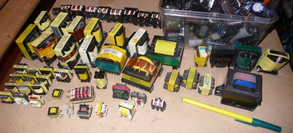
Transformers. Might be able to repurpose these for GDTs, if needed.

Ferrite cores. 1.4" ID, 2.4" OD, and the total stack of 5 is 2.5" tall. Shoudl be ballpark good enough, I'll calculate that soon, but I have much bigger backups if need be.
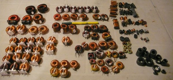
COils/Chokes. Someone suggested these would make good GDTs. They suggested to use the ones with thin wire, not the heavier 16g wire ones because they'll saturate as transfomers.
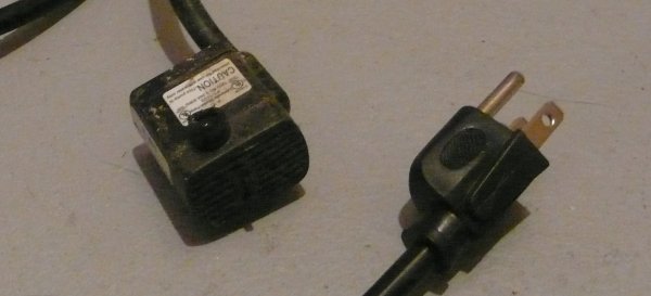
Baby water pump. 0.04A.
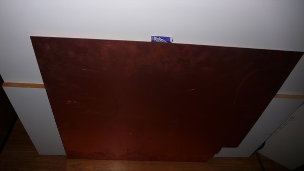
Double-sided circuitboard blank. A few square feet.
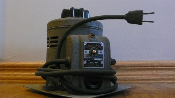
7.5A variac. I have a 12.5A laying around somewhere too. Good enough to skip building a giant Buck regulator for the 120V demo.
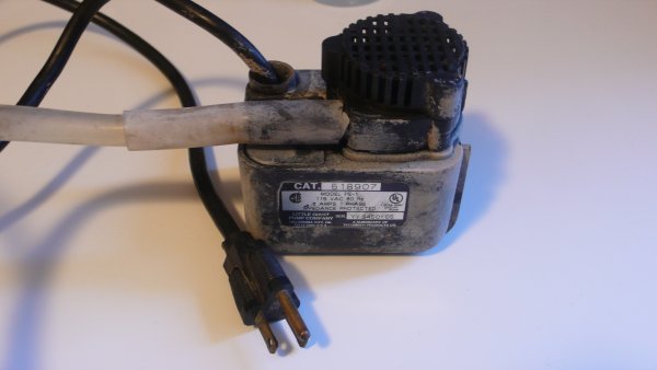
Big water pump. Good for 170 gallons/hour (2.8 gallons/minute).
It's no induction heater, but it's on it's way.
AwesomeMatt, Wed Aug 27 2014, 12:48AM
Well I have a friend who'll ship and loan/sell me some suitable caps, at least until after the Faire.
Running out of time, 10 days.
 <-- Uzzor's new driver, I'll be cloning this.
 <-- IAMSMOOTH's big power side circuit. I'll be cloning most of this.
I would ideally like to copy IAMSMOOTH's whole circuit with the arduino and all, but his code isn't posted anywhere and I don't trust myself to write it from scratch, hence, going with Uzzors' pre-driver.
Since I'm only building a 6KW unit, not a 10KW unit, I was hoping to save some money on the MOSFETs, not copy IAMSMOOTH's circuit entirely... but I don't know the specs I'd need.
He uses higher voltage (has a doubler) to feed his inverter.. I'm using 300VDC. I'm not sure if the MOSFETs need extra, (400, 500, or 600V instead of 300?) or if you can just rate them for what you give them. I'm also not sure about the amps. The breaker is 30A, but can I just choose MOSFETs that are 30A, or should I include safety margin (say, 50 or 60A?).
I also need:
- 1x LM393 (op amp?)
- 2x LM358 (op amp? why different than 393?)
- 1x TC4421 (gate driver)
- 1x TC4422 (gate driver, inverting)
- Maybe some superfast diodes, if I can't salvage from computer PSUs.
- 4x 18v zeners (how many amps?)
I presume I can just copy these components outright, no need to tweak them for different MOSFETs or whatever else in my design is slightly different.
I started taking pics of stuff:

Transformers. Might be able to repurpose these for GDTs, if needed.

Ferrite cores. 1.4" ID, 2.4" OD, and the total stack of 5 is 2.5" tall. Shoudl be ballpark good enough, I'll calculate that soon, but I have much bigger backups if need be.

COils/Chokes. Someone suggested these would make good GDTs. They suggested to use the ones with thin wire, not the heavier 16g wire ones because they'll saturate as transfomers.

Baby water pump. 0.04A.

Double-sided circuitboard blank. A few square feet.

7.5A variac. I have a 12.5A laying around somewhere too. Good enough to skip building a giant Buck regulator for the 120V demo.

Big water pump. Good for 170 gallons/hour (2.8 gallons/minute).
It's no induction heater, but it's on it's way.
Re: Novice-Built Induction Heater (In 14 days?)
IamSmooth, Wed Aug 27 2014, 02:41AM
You can levitate aluminum using my 2-3kw circuit and manually tune with the assistance of a PLL. It will run off of 120vac. You can build it in a day. You can get away with just air cooling for your mosfets. You can just copy this entire circuit and accomplish your task.
Here is a video of the 3kw unit doing what you want using manual tuning (no arduino):
It is the first schematic on the tutorial.
3kw unit here:
Levitation section of tutorial here:
The key to levitation is copying the coil topology on my website tutorial. This appears at the very end under the levitation section. Copper and steel levitation require close to 10kw. Sustained levitation during a completely molten state requires over 12-15kw. You better have some good mosfet cooling for this.
IamSmooth, Wed Aug 27 2014, 02:41AM
You can levitate aluminum using my 2-3kw circuit and manually tune with the assistance of a PLL. It will run off of 120vac. You can build it in a day. You can get away with just air cooling for your mosfets. You can just copy this entire circuit and accomplish your task.
Here is a video of the 3kw unit doing what you want using manual tuning (no arduino):

It is the first schematic on the tutorial.
3kw unit here:

Levitation section of tutorial here:

The key to levitation is copying the coil topology on my website tutorial. This appears at the very end under the levitation section. Copper and steel levitation require close to 10kw. Sustained levitation during a completely molten state requires over 12-15kw. You better have some good mosfet cooling for this.
Re: Novice-Built Induction Heater (In 14 days?)
AwesomeMatt, Wed Aug 27 2014, 08:43AM
Smooth - I've read your tutorials and seen your vids 10x each. Very helpful. Some of it is over my head.
I leaned towards Uzzor's driver because it does more automatically and needs less setup. Or appears to. I'd ideally add an arduino just like you did eventually, when I'm not under such a time crunch.
Re: Novice-Built Induction Heater (In 14 days?)
AwesomeMatt, Thu Aug 28 2014, 03:15AM
TL;DR - Boring philosophy on novices with electronics.
So I went to order parts today. Even with a schematic I was copying, this was a lot more work than I anticipated, with a lot less certainty that I did it right.
For example:
- I need a simple op-amp. LM393.
- I punch it into Digikey... out comes 138 different options. O.o
- Being a novice, I'll just use big clumsy through-hole parts. 138 --> 12.
- Wanting cheap and quick shipping, local (Canadian) stock only. 12 --> 7.
- Okay, 7 to choose from. Main difference is "Differential" vs. "General Purpose". Uh oh.
- I wonder: "Does any of this matter?", "If I picked randomly, would it still work?", "Would any op-amp at all (LM393 just being a generic) work just as well?
- Inputs range from either 2mV or 5mV, and end at either 30V or 5V. I don't know what voltage range they're being used for in this circuit.
- Higher voltage range seems better as a guess, but, if it was designed for the lower range I'd lose... precision? Would my range be off? Would it matter at all?
- Max input bias is either 0.1uA or 0.25uA.. hrm.
- Output current is 16, 18, or 20mA. I know what this means, but not what is required.
- I sort by # in stock and pick the one that seems most popular.
- I have no clue if that was the correct decision.
Suddenly I went from "Great, I'll just grab this part" to "There are 20 contextual questions I don't know how to answer."
This is repeated for every part.
The trouble of blindly following instructions without context is the inability to solve my own problems. So if instructions aren't perfect ("Use these exact parts"), or my use differs slighly, I've got nothing to go on.
This is one of the things that's always intimidated me about electronics. I have no interest in basic LED blinky stuff, but the stuff I would use I don't understand.
I'm sure I have the ability to understand more complicated circuits, but my brain works differently than most electronics people's. I get nothing out of a static schematic. But if I can see how the circuit evolves from both ends "Input is around here, Output needs to be this"... and how and why parts fall into place in sequence... electronics is very simple and building-block like.
I see a schematic as a narrative. "In order to get E we need to have D, in order to set D we need to control C. In order to control C we need to supply it with B, and B can be had from A." But when I see the end result without those choices, it makes no sense to me.
But by the point I could answer all these questions, I wouldn't need to copy someone else's circuit. I'd just know how to create one myself.
Re: Novice-Built Induction Heater (In 14 days?)
Steve Conner, Thu Aug 28 2014, 06:40AM
At this sort of level you should be using the same part that the designer of the circuit called out. If the schematic says to use a LM393 then that is what you use. Once you understand the theory behind what is going on, you can make substitutions. (For example, the LM393 in Uzzors' circuit is a comparator, not an opamp, and if you had substituted an opamp the circuit would not work.)
Popular parts are often "second-sourced" by several manufacturers. The first two letters denote the manufacturer. So the 555 timer is available as a NE555, LM555, uA555, KA555 and so on. Again these are supposed to be identical. There are some minor differences, but a good circuit design will work the same with any of them. (But watch out for CMOS ones like the ICM7555.)
Opamps are often available in a premium grade selected for low offset voltage. This is usually indicated by an A in the part number. Again if the circuit needs the A grade to perform, it should be called out.
Outside of these considerations, just pick the package style you want (I use DIP for prototyping too when possible) then pick the cheapest one or whatever is in stock.
Re: Novice-Built Induction Heater (In 14 days?)
AwesomeMatt, Thu Aug 28 2014, 01:26PM
Yes, this much I get, if the circuits I received were from paid professionals with expectations for documentation. When my sources for schematics are volunteer hobbyists who're sometimes amateurs... it's not reasonable to assume the same thoroughness was taken (or expected, they're taking time out of their day to share for free).
Good, this is what I had been doing and was feeling rather uneasy about it.
...
I sorted about 20 pounds of salvaged components tonight, found all kinds of things I didn't know I had. I've got a half-dozen Schottky diodes in TO-247, and a dozens more in TO-220. Lots of MOSFETS, some that appear to actually be powerful enough to avoid needing to purchase... but they're salvaged so I'll spend the big bucks while I'm already ordering ($22 each). Some of almost every small component. A stack of 4046s. Suitable pots, suitable power resistors. Feeling confident.
I'm also not sure whether to go with Uzzor's gate driver (UC3710T) which is both low and high side... or IAmSmooth's TC4422 & TC 4421.
Smooth seems to have more paranoia and robustness built into his design. His fets are overbuilt, he has zeners across them, his caps on the drivers are much larger too, but his caps on the MOSFET side are 1/10th as big. Uzzors's also has a 4-pack of 1N5819 schottkys on his drivers, Smooth has none. Smooth actually runs his at 10+kW, Uzzors designed for 1600W and IIRC that non-obvious (not just bigger mosfets/support components) design issues start to creep up on a design past 3kW.
I'm not sure which is smarter to emulate.
AwesomeMatt, Thu Aug 28 2014, 01:26PM
wrote ...
Again if the circuit needs the A grade to perform, it should be called out.
Again if the circuit needs the A grade to perform, it should be called out.
Yes, this much I get, if the circuits I received were from paid professionals with expectations for documentation. When my sources for schematics are volunteer hobbyists who're sometimes amateurs... it's not reasonable to assume the same thoroughness was taken (or expected, they're taking time out of their day to share for free).
wrote ...
Outside of these considerations, just pick the package style you want (I use DIP for prototyping too when possible) then pick the cheapest one or whatever is in stock.
Outside of these considerations, just pick the package style you want (I use DIP for prototyping too when possible) then pick the cheapest one or whatever is in stock.
Good, this is what I had been doing and was feeling rather uneasy about it.
...
I sorted about 20 pounds of salvaged components tonight, found all kinds of things I didn't know I had. I've got a half-dozen Schottky diodes in TO-247, and a dozens more in TO-220. Lots of MOSFETS, some that appear to actually be powerful enough to avoid needing to purchase... but they're salvaged so I'll spend the big bucks while I'm already ordering ($22 each). Some of almost every small component. A stack of 4046s. Suitable pots, suitable power resistors. Feeling confident.
I'm also not sure whether to go with Uzzor's gate driver (UC3710T) which is both low and high side... or IAmSmooth's TC4422 & TC 4421.
Smooth seems to have more paranoia and robustness built into his design. His fets are overbuilt, he has zeners across them, his caps on the drivers are much larger too, but his caps on the MOSFET side are 1/10th as big. Uzzors's also has a 4-pack of 1N5819 schottkys on his drivers, Smooth has none. Smooth actually runs his at 10+kW, Uzzors designed for 1600W and IIRC that non-obvious (not just bigger mosfets/support components) design issues start to creep up on a design past 3kW.
I'm not sure which is smarter to emulate.
Re: Novice-Built Induction Heater (In 14 days?)
AwesomeMatt, Tue Sept 09 2014, 06:31AM
UPDATE - FAIL.
Naysayers, commence your toldjasos.
I think I could have completed it on time, had my (borrowed and rush shipped) capacitors not shown up the afternoon before. That, and had I not knocked over my partsbins the same day, spilling tens of thousands of components all over the carpet. That, and had I not chosen to spend my time getting more important faire-related tasks completed.
IT'S OKAY.
I had a blast at our Makerfaire anyway and showed off some other projects and spent my time volunteering for many other things instead. I almost would have been too busy to be stuck supervising the induction heater.
I never cashed the cheque for the funding grant, and I've offered it be returned if they would prefer. I don't think anyone was too upset, no one else got their funded projects done on time either.
Either way, still continuing the build. This time with a less frantic pace and ghetto approach. In fact, I will probably build 2 units, a 120V and a 240V version.
But first, I promised a documented build, and I've been slacking. Here are more build pics:
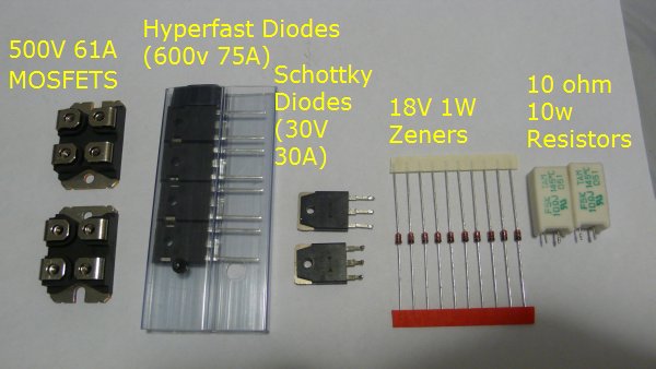
Power components. Schottky's I found in my partsbins, I have dozens. I'll probably twin them up just to be safe, since I'll be pushing near 30A.
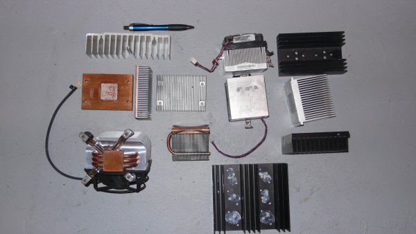
Heatsinks. This and several cubic feet more. I'll probably go with the copper bottomed ones left-mid. Not sure if I'll use fan or water cooling for the fets.
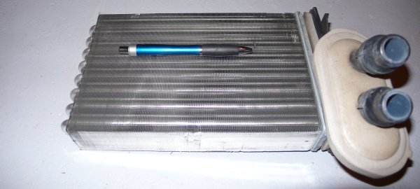
For water cooling, a "heater core". I mentioned what I was making, and a friend said we should make a trip back to his place to pull a heater core out of some car scraps under his deck. Looks good to me. Fins are so thin and dense it probably needs a heafty fan. Not an issue.
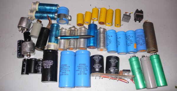
To smooth input power, some bigass rectifiers (top right), and some old caps. 208V smoothed is 300VDC, I'll be planning for 400V just to be safe. These are all actually kinda crappy, large for how puny their values are, so...
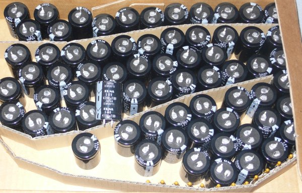
71 of these, new and unused. 50v, 4700uF. Means I'll use strings of 8 in series for ~600uF, and then start chaining them up in parallel. I've been told to put in as many caps as I can, somewhere around 5000uF @ 400V should suffice. This box could do, nice because they're all matched.
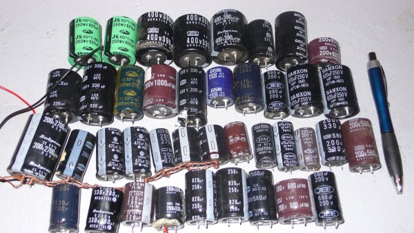
... Or, my higher voltage electrolytics. Lots of 400+V in here, lots of 200V as well. Bit more of a pain, since they're mismatched sizes.
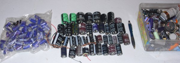
Failing that I still have a another cubic foot of electrolytics left over, I'll make it work.
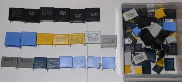
The electrolytics provide the bulk power to the inverter and are fine for the 60hz they're trying to smooth, but the inverter still needs a supply of power that can be drained quickly and rapidly in the tens of kilohertz... electrolytics can't handle that. Up steps the MKPX2 caps.
On the left are all 250v 1uF+. On the right are my bin full of smaller ones.
I'll probably stack the 250v in series pairs for 500V. It'll still be good for 10uF.
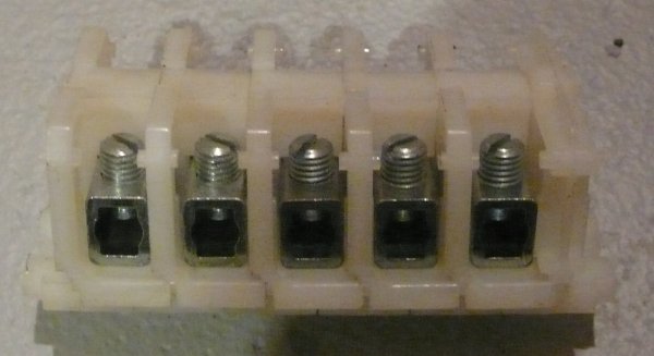
Big (huge, 1/4") terminal blocks. Good for my main wiring. I've got lots of these for when I need them.
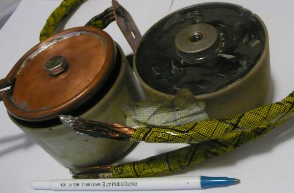
Tank caps. 600Vrms, 158 Aeff, 3.1uF. I borrowed these and rush shipped them. I will probably keep them and just pay to replace his when he finds a good deal, since they weren't too much what he needed.
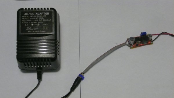
12V 2000mA wall wart for the PLL/driver circuit, and a 3A (chinese amps, so, needs a heatsink for more than 1A or the solder melts) buck regulator to hold it there.
Also, someone suggested to me that on Uzzor's circuit ( ), the 12V rail and the 15V rail would be just fine at both being the same 12V rail so that's how I wired my PLL.
More on the PLL later.
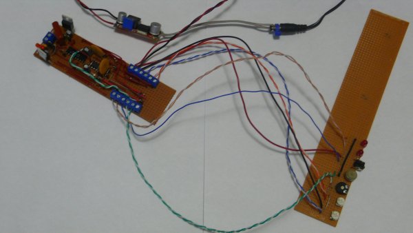
PLL/driver board, and all the stuff that's getting mounted on the case: Drive Enabled LED, PLL LOcked LED, Reset button, pot for Peak Tank Cap voltage, pot for Phase Adjust, pots for R1 and R2 (for testing, may hardwire).
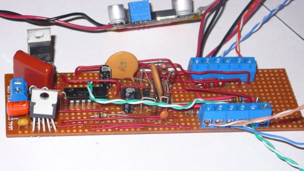
Closeup of the PLL/Driver baord on stripboard.
I don't know how to turn a schematic into a physical circuit, so I just tried to think ahead a little bit and otherwise went one component and one connection at a time. My partsbins landed on it and bent some of it.
.......
End photos.
So far, when I plug it in, without any GDT connected and pots set roughly to the range I want them... nothing happens to the LEDs. Also though, the chinese buck regulator flatlines at 2.47 amps (probably it's max) and the output voltage on the buck is only 0.25V (input is ~12V).
So, my guess is that the power is sagging down to almost zero because:
1 - There's a short somewhere.
2 - The PLL/driver board takes a hell of a lot more than just 2.5A to power.
3 - Maybe this is normal behavior when no load is connected?
That's where I am today.
AwesomeMatt, Tue Sept 09 2014, 06:31AM
UPDATE - FAIL.
Naysayers, commence your toldjasos.
I think I could have completed it on time, had my (borrowed and rush shipped) capacitors not shown up the afternoon before. That, and had I not knocked over my partsbins the same day, spilling tens of thousands of components all over the carpet. That, and had I not chosen to spend my time getting more important faire-related tasks completed.
IT'S OKAY.
I had a blast at our Makerfaire anyway and showed off some other projects and spent my time volunteering for many other things instead. I almost would have been too busy to be stuck supervising the induction heater.
I never cashed the cheque for the funding grant, and I've offered it be returned if they would prefer. I don't think anyone was too upset, no one else got their funded projects done on time either.
Either way, still continuing the build. This time with a less frantic pace and ghetto approach. In fact, I will probably build 2 units, a 120V and a 240V version.
But first, I promised a documented build, and I've been slacking. Here are more build pics:

Power components. Schottky's I found in my partsbins, I have dozens. I'll probably twin them up just to be safe, since I'll be pushing near 30A.

Heatsinks. This and several cubic feet more. I'll probably go with the copper bottomed ones left-mid. Not sure if I'll use fan or water cooling for the fets.

For water cooling, a "heater core". I mentioned what I was making, and a friend said we should make a trip back to his place to pull a heater core out of some car scraps under his deck. Looks good to me. Fins are so thin and dense it probably needs a heafty fan. Not an issue.

To smooth input power, some bigass rectifiers (top right), and some old caps. 208V smoothed is 300VDC, I'll be planning for 400V just to be safe. These are all actually kinda crappy, large for how puny their values are, so...

71 of these, new and unused. 50v, 4700uF. Means I'll use strings of 8 in series for ~600uF, and then start chaining them up in parallel. I've been told to put in as many caps as I can, somewhere around 5000uF @ 400V should suffice. This box could do, nice because they're all matched.

... Or, my higher voltage electrolytics. Lots of 400+V in here, lots of 200V as well. Bit more of a pain, since they're mismatched sizes.

Failing that I still have a another cubic foot of electrolytics left over, I'll make it work.

The electrolytics provide the bulk power to the inverter and are fine for the 60hz they're trying to smooth, but the inverter still needs a supply of power that can be drained quickly and rapidly in the tens of kilohertz... electrolytics can't handle that. Up steps the MKPX2 caps.
On the left are all 250v 1uF+. On the right are my bin full of smaller ones.
I'll probably stack the 250v in series pairs for 500V. It'll still be good for 10uF.

Big (huge, 1/4") terminal blocks. Good for my main wiring. I've got lots of these for when I need them.

Tank caps. 600Vrms, 158 Aeff, 3.1uF. I borrowed these and rush shipped them. I will probably keep them and just pay to replace his when he finds a good deal, since they weren't too much what he needed.

12V 2000mA wall wart for the PLL/driver circuit, and a 3A (chinese amps, so, needs a heatsink for more than 1A or the solder melts) buck regulator to hold it there.
Also, someone suggested to me that on Uzzor's circuit (
 ), the 12V rail and the 15V rail would be just fine at both being the same 12V rail so that's how I wired my PLL.
More on the PLL later.

PLL/driver board, and all the stuff that's getting mounted on the case: Drive Enabled LED, PLL LOcked LED, Reset button, pot for Peak Tank Cap voltage, pot for Phase Adjust, pots for R1 and R2 (for testing, may hardwire).

Closeup of the PLL/Driver baord on stripboard.
I don't know how to turn a schematic into a physical circuit, so I just tried to think ahead a little bit and otherwise went one component and one connection at a time. My partsbins landed on it and bent some of it.
.......
End photos.
So far, when I plug it in, without any GDT connected and pots set roughly to the range I want them... nothing happens to the LEDs. Also though, the chinese buck regulator flatlines at 2.47 amps (probably it's max) and the output voltage on the buck is only 0.25V (input is ~12V).
So, my guess is that the power is sagging down to almost zero because:
1 - There's a short somewhere.
2 - The PLL/driver board takes a hell of a lot more than just 2.5A to power.
3 - Maybe this is normal behavior when no load is connected?
That's where I am today.
Re: Novice-Built Induction Heater (In 14 days?)
Wolfram, Tue Sept 09 2014, 10:41AM
You don't want too much smoothing capacitance across the DC bus, it will only serve to ruin your power factor. Unsmoothed rectified mains will heat just as well as smooth DC. Some film caps across the DC bus to take care of the ripple at the driving frequency is all that is needed.
Print this page