
Quick IGBT failure in DRSSTC
chris_inkubate, Fri Jul 25 2014, 07:03PMHi there,
I have been doing some tests on my new DRSSTC that I'm working on but have had an exploded IGBT. However this explosion happened during burst mode operation where I suspect power dissipation wasn't too extreme as the heat sinks were not getting particularly hot at all. The details are as follows:
- IRG4PC50UD full bridge
- 350V bus
- over current protection at around 250A
- 7.5 turns on primary
- 176nF tank capacitor
- 4700uF bus capacitor
- TVS protection on IGBT's
- 2 x 10uf polyprop capacitors as snubbers
- Steve wards older driver
The fail has also blown the tracks into the collectors of both the IGBT's on one side of the H Bridge - I'm guessing that one failed short circuit and then when the other switched on the bus capacitor was essentially shorted through the IGBT's with all 4700uf dropped across them! Can anyone let me know if this makes sense please?
I'd also welcome any insight as to what may have caused the IGBT failure as I suspect 250A isn't excessive for the IGBT particularly as I'd only been running in burst mode and even then for 3 or 4 second runs.
Many Thanks,
Chris
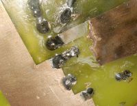
Re: Quick IGBT failure in DRSSTC
Mads Barnkob, Fri Jul 25 2014, 07:55PM
Look at the bottom graph at page 4 in the datasheet:
The thermal impedance raises fast with pulse duration for small devices like the To-247, they do not at all match the longer pulse durations that larger IGBT bricks do, as they still have quite low thermal impedances at those on-times and by long we are talking under 500uS.
My guess is that your junction temperature simply could not cool down fast enough between the bursts and suddenly it melts, short out the supply and the weakest point in your bridge construction is the tracks of the PCB that blows off.
250A peak current is close to the limit of TO-247 devices, I think I blew some at 350A from excessive peak current. You likely blew them from too long on-time.
Mads Barnkob, Fri Jul 25 2014, 07:55PM
chris_inkubate wrote ...
The fail has also blown the tracks into the collectors of both the IGBT's on one side of the H Bridge - I'm guessing that one failed short circuit and then when the other switched on the bus capacitor was essentially shorted through the IGBT's with all 4700uf dropped across them! Can anyone let me know if this makes sense please?
I'd also welcome any insight as to what may have caused the IGBT failure as I suspect 250A isn't excessive for the IGBT particularly as I'd only been running in burst mode and even then for 3 or 4 second runs.
Look at the bottom graph at page 4 in the datasheet:

The thermal impedance raises fast with pulse duration for small devices like the To-247, they do not at all match the longer pulse durations that larger IGBT bricks do, as they still have quite low thermal impedances at those on-times and by long we are talking under 500uS.
My guess is that your junction temperature simply could not cool down fast enough between the bursts and suddenly it melts, short out the supply and the weakest point in your bridge construction is the tracks of the PCB that blows off.
250A peak current is close to the limit of TO-247 devices, I think I blew some at 350A from excessive peak current. You likely blew them from too long on-time.
Re: Quick IGBT failure in DRSSTC
Goodchild, Fri Jul 25 2014, 08:01PM
The failure that you are seeing were one IGBT fails and then kills the other is very common (also known as crowbar) and will happen almost every time an IGBTs fails unless you have a very fast OCD scheme that can shut off mid cycle. However most DR drivers will only shut off at the end of a zero crossing so it’s unlikely that you will be able to mitigate the crow-baring effect without changing the OCD scheme significantly.
The first IGBT most likely failed from one of two things the first being over current, which is likely considering you are running right over the SOA of those IGBTs.
The second is an overvoltage transient on your bus. TVS across a bus layout is rather useless, because they will not be able to absorb the kid of energy associated with an event like this, let alone react in time. Bus transients are usually caused by poor bus layout, or abnormal parasitic oscillation in the IGBT and bus copper. A good way to check is to scope your inverter output while running at lower power. If you have an abnormal amount of ringing at the voltage transitions, this is likely what caused the IGBT failure.
We may be able to help further if you post a photo of your bus layout and a scope shot of your inverter out voltage.
Re: Quick IGBT failure in DRSSTC
chris_inkubate, Fri Jul 25 2014, 08:56PM
Thanks for the replies and its certainly interesting to learn about the thermal impedance vs. pulse duration. I was taking some liberty running those IGBT's over current but believe this isn't uncommon for this device in DRSSTC use, but I suppose it all depends on the specs of the coil they are used in!
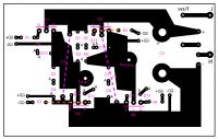
I have attached an image of my bus of which I'm not sure how good/bad it is in real terms. Would I be correct in thinking that there could be fairly high voltages on the inverter output even at low say 24V in and low duty cycle? Just a little concerned that if I scope the output that I do it safely!
Many Thanks
chris_inkubate, Fri Jul 25 2014, 08:56PM
Thanks for the replies and its certainly interesting to learn about the thermal impedance vs. pulse duration. I was taking some liberty running those IGBT's over current but believe this isn't uncommon for this device in DRSSTC use, but I suppose it all depends on the specs of the coil they are used in!
I have attached an image of my bus of which I'm not sure how good/bad it is in real terms. Would I be correct in thinking that there could be fairly high voltages on the inverter output even at low say 24V in and low duty cycle? Just a little concerned that if I scope the output that I do it safely!

Many Thanks
Re: Quick IGBT failure in DRSSTC
Goodchild, Fri Jul 25 2014, 09:12PM
Well, your bus layout is not really optimal. Your + - bus planes are far away from each other and not overlapping. I wouldn’t be surprised if you had excessive ringing on your inverter output. If you plan on simply replacing your IGBTs I would look at your output voltage on a scope and see how bad the issue really is.
As per my previous statement, I’m now leaning to overvoltage as your failure condition. However, you still need to verify this before taking any corrective action.
Also in regards to the thermal impedance data in the datasheet, use that data carefully. That data only models the thermal impedance from die to case. Without incorporating your cooling solution into that model, that data is not very helpful.
Re: Quick IGBT failure in DRSSTC
Mads Barnkob, Fri Jul 25 2014, 10:17PM
I agree that the PCB layout is not optimal, but this is a single sided board and there is C3 and C4 snubbers across the DC bus, right at the switches, it is still a good idea to check your inverter output waveforms if you can, be sure to use a isolation transformer for the bridge supply or a differential probe to avoid damaging your oscilloscope..
I would get rid of all 90 degree corners and have it all 45 degree or round, you have so many places where you could just fill it out to a larger plane, get some more trace width in around those IGBTs, move some of the other components a bit away so there is room for power traces.
I do however disagree that the thermal impedance data is not helpful, there is so little mass and material in TO-247 packages to absorb and transfer heat that it is a issue not to take on lightly. Our very low on-times is the very reason we can run the IGBT switches over the rated peak current as the generated heat can dissipate in-between bursts. If it is mounted on a normal heat sink you can slide the X axis some, but it will still, roughly estimated, scale the same for that cooling method.
I attached a application note by Powerex on the thermal impedance issue
]zth_underchip_nf.pdf[/file]
Re: Quick IGBT failure in DRSSTC
chris_inkubate, Fri Jul 25 2014, 10:36PM
I'll certainly look into re-designing the PCB taking into account this feedback. I assume I can really just leave out the TVS's which will allow more room for power bus tracks.
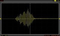
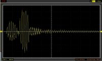
I managed to get these scope captures of the output which hopefully may make some sense. I had to scope the OCD burden resistor as my scope is only a Chinese PC oscilloscope and kept locking up directly connected!
Cheers,
Chris


Re: Quick IGBT failure in DRSSTC
Mads Barnkob, Sat Jul 26 2014, 06:39AM
I think that 350uS is way too long on-time for a DRSSTC using TO-247 switches, instead of using long on-times to get a good break out you should try to tune it more precisely and you will see you can get a better output at under 100uS.
Please someone correct me if im wrong about te following: The steps seen in the first shot is actually 4-5 cycles of power transfer to the secondary coil. Effectively is works the same as burst mode that it is just on for such a long time that more cycles find place.
The small ripple in your traces could be parasitic ringing, but as it oscillates at 1MHz and that is also the sample rate of your cheap Chinese scope, it could just be that it picks up some noise at every sample.
Re: Quick IGBT failure in DRSSTC
chris_inkubate, Sat Jul 26 2014, 11:54AM
I've now replaced the IGBT's with four ST STGW80V60DF parts and keeping the on time at 100us max and no failure as yet. Getting around 26" arcs so will work more on tuning and then onto optimising my PCB bus and see how much more I can get from it. Thanks for the feedback so far - I have some brick IGBT's but wanted to learn the ropes with cheap IGBT's that I don't mind as much destroying. Which is whats happened!
Re: Quick IGBT failure in DRSSTC
Steve Ward, Sun Jul 27 2014, 02:51AM
Chris,
I think your IGBTs are just failing from over-temp.
Using phase lead could lower the power dissipation in the IGBTs by maybe 10-30% compared with my "old driver", especially if the resonant frequency is high.
Its helpful to judge an IGBTs ruggedness by its thermal resistance from junction to case (Rjc). The power ratings of a TO-247 IGBT can range from maybe 100W to 1000W, and its purely related to how big the chip is inside. Bigger chips clearly can dissipate more heat. Your IRG4PC50UD has a Rjc of 0.64 *C/W, and the STGW80V60DF has Rjc = 0.32. The ST part likely has about 2X the silicon area compared to the IR part, and yet they have nearly the same peak collector current spec. The difference will be how quickly the IR part heats up during a "burst" vs the ST part, having twice the thermal capacity makes a big difference, hence it survives. If you shop around you can find TO-247 devices with Rjc < 0.2 or even .1 (though they dont have mounting holes by that point, you need to clamp them).
Also beware of the thermal resistance that those transistor isolating films/pads give. The highest performing, inexpensive option seems to be very thin 1 mil kapton film with just the right amount of thermal compound. I calculate that the 1mil film gives about .5 *C/W resistance from the case to the heatsink, which is significantly more than the junction-to-case resistance. Those silicone rubber types can vary from about twice that resistance to several times higher, making the thermal resistance easily 10X the junction-to-case resistance, basically crippling the parts. Mounting the parts directly to individual heatsinks can drastically imrpove an IGBTs performance.
Re: Quick IGBT failure in DRSSTC
Hydron, Sun Jul 27 2014, 06:58AM
In commercial applications I've seen TO-247 parts clamped directly (with thermal compound) to copper heat spreading plates (which are much larger than the transistor case), with the plate itself then clamped to the heatsink with a very large silpad for insulation. This is done to try and defeat the problem Steve mentioned - large thermal resistance due to the electrical insulator. There is added thermal resistance there due to the extra junction, but at least the worst one with the silpad is much lower resistance due to the large area.
Edit: of course the most effective option is to have isolated heatsinks so the transistors can be mounted directly on them. This has a whole different set of issues however!
Re: Quick IGBT failure in DRSSTC
chris_inkubate, Sun Jul 27 2014, 12:10PM
Thats interesting information and I'll take a look at those specs in some other parts and see how they compare. I did notice that the ST part has a lot larger continuous current capacity so this suggests that its a better performer too. The data also states its can handle 120A continuous at 25*C although I'm not sure that the junction could ever be kept that low in practice!
My operating frequency is 85KHz with my secondary just above this at around 90KHz so not too high. My coil is deliberately bigger so I can use the same system with bricks once I understand things a little better. I'll also be using phase lead on those once I put together an updated driver.
Let see if I can keep these ST parts alive for a while. I may push them a little harder when I get closer to building the updated bridge and see what they can do without being too bothered about the loss!
Many Thanks
chris_inkubate, Sun Jul 27 2014, 12:10PM
Steve Ward wrote ...
Bigger chips clearly can dissipate more heat. Your IRG4PC50UD has a Rjc of 0.64 *C/W, and the STGW80V60DF has Rjc = 0.32. The ST part likely has about 2X the silicon area compared to the IR part, and yet they have nearly the same peak collector current spec. The difference will be how quickly the IR part heats up during a "burst" vs the ST part, having twice the thermal capacity makes a big difference, hence it survives. If you shop around you can find TO-247 devices with Rjc < 0.2 or even .1 (though they dont have mounting holes by that point, you need to clamp them).
Bigger chips clearly can dissipate more heat. Your IRG4PC50UD has a Rjc of 0.64 *C/W, and the STGW80V60DF has Rjc = 0.32. The ST part likely has about 2X the silicon area compared to the IR part, and yet they have nearly the same peak collector current spec. The difference will be how quickly the IR part heats up during a "burst" vs the ST part, having twice the thermal capacity makes a big difference, hence it survives. If you shop around you can find TO-247 devices with Rjc < 0.2 or even .1 (though they dont have mounting holes by that point, you need to clamp them).
Thats interesting information and I'll take a look at those specs in some other parts and see how they compare. I did notice that the ST part has a lot larger continuous current capacity so this suggests that its a better performer too. The data also states its can handle 120A continuous at 25*C although I'm not sure that the junction could ever be kept that low in practice!
My operating frequency is 85KHz with my secondary just above this at around 90KHz so not too high. My coil is deliberately bigger so I can use the same system with bricks once I understand things a little better. I'll also be using phase lead on those once I put together an updated driver.
Let see if I can keep these ST parts alive for a while. I may push them a little harder when I get closer to building the updated bridge and see what they can do without being too bothered about the loss!
Many Thanks
Re: Quick IGBT failure in DRSSTC
Maurizio Valvo, Mon Jul 28 2014, 08:25PM
Hi, I think another thing you should check is gate drive waveform and particularly amplitude: this should be close to the maximum rating of the IGBT (or even a bit higher, if you want to take some risk ...) to prevent desaturation, especially when the IGBT is operated at very high peak currents.
For comparison, I'm also using a full bridge of TO-247 IGBTs, IXGR60N60C2D1, mounted on a PCB, never blown any (I cross fingers ...); they have slightly better current characteristics then your IR type (Icm=300A) and isolated case which makes mounting them on a common heatsink quite straightforward (even so they have a lower junction to case thermal resistance, 0.5C/W, then your IR type). I use Steve's old driver (no phase lead), my OCD is set to 450A (i.e. 50% higher than Icm rating!, limiting most of the time), bus cap is 3200uF, voltage is rectified 230V, tank cap about 90nF, resonant frequency about 130kHz, max spark length (up to now ...) 120cm. My interrupter generates over 300us pulses, although OCD limits the burst length. Gate drive amplitude is around 30V, which is the transient max rating of my IGBTs.
Re: Quick IGBT failure in DRSSTC
chris_inkubate, Tue Jul 29 2014, 10:50PM
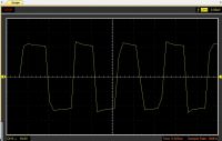
My gate waveform looks a healthy voltage just over the top spec of the IGBT. I am concerned that the rise / fall times are a bit slow but have noticed that the primary feedback has a habit of dropping out and the interrupter signal restarting the switching when the bus is at low voltage with and running short pulse widths. My scope is only a PC based one and really doesn't like it when the power goes up so getting measurements at higher power is impossible.
I think I'll spend some time trying to record all waveforms across the system to check all is OK.

Re: Quick IGBT failure in DRSSTC
Hydron, Wed Jul 30 2014, 04:10AM
If at all possible try and use a faster scope to record your waveforms.
Your gate drive screenshot only seems to be sampled at 1MHz (despite saying 16MHz), this is not nearly fast enough to accurately capture ringing, risetime etc on fast signals such as gate drive and the (voltage) output of the bridge (may be quick enough for tank current however).
Edit: if you persist in using that scope, try and wrap the USB and probe leads through ferrites to block some of the common mode noise. USB is extremely susceptible to common mode noise (despite mostly using differential signalling), and I had some similar problems with my scope before I had it converted to ethernet.
Also, you mentioned that the rise/fall times were slow - I wouldn't draw any conclusions about that until you get better measurements, as you're not sampling fast enough to actually tell what they are.
Re: Quick IGBT failure in DRSSTC
chris_inkubate, Fri Aug 01 2014, 08:30PM
Well I discovered something today that seems to have been holding my coil back a lot. One of the back to back zener diodes protecting an IGBT gate had gone bad and finally short circuit causing my gate resistor to cook! I replaced my diodes and now I'm getting better results with under 100us on that I was previously getting with 350us on times. I suspect that this diode may have always been dodgy because the coil is now hitting 75cm arcs with this much lower on time, not even lighting my OCD protection set at 220A and I havent tried moving the ground further yet so will probably do more. I was only getting around 60cm tops before whilst running at the 250A mark.
Would it be feasible that this zener could have been faulty before I blew two IGBT's and may have contributed in some way? And would the coil have been working in some kind of half bridge mode hence the shorter arcs?
Its all certainly proving to be a learning curve!
Many Thanks
Re: Quick IGBT failure in DRSSTC
chris_inkubate, Sun Aug 24 2014, 01:33PM
Hi all,
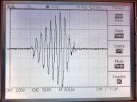
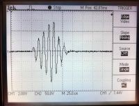
I have now got access to a better scope for a couple of days and got some waveforms taken with a 1000:1 current transformer (home made with 22R burden) over the connection between the tank cap and primary. From what I can see these look fine but would appreciate any feedback if anyone notices anything?
Also how quickly should I expect the OCD protection to cut in? Mine is set to come in at 6V which would be 272A but on the waveform it peaked at 341A for one cycle! The OCD is however working I think as the on time doesn't increase after this point despite increasing the interrupter.
Many Thanks, Chris


Re: Quick IGBT failure in DRSSTC
loneoceans, Sun Aug 24 2014, 04:31PM
Which driver are you using? Most DRSSTC drivers use a flip flop to make sure the IGBTs only switch at zero current, so if the OCD trips as the current is rising up, it will not turn off your driver until the next zero crossing, so the current (in that cycle) can continue to ramp up evern more. Just something to take note.
Re: Quick IGBT failure in DRSSTC
Steve Conner, Sun Aug 24 2014, 05:28PM
Correct, the actual peak current you see can be maybe 20% more than the OCD trip setting.
Steve Conner, Sun Aug 24 2014, 05:28PM
Correct, the actual peak current you see can be maybe 20% more than the OCD trip setting.
Re: Quick IGBT failure in DRSSTC
chris_inkubate, Sun Aug 24 2014, 07:52PM
Thanks for the replies. That makes sense as my driver is Steve Wards original which does use a flip flop as part of the current limiting circuit. My current when using the original IRG4PC50UD parts must have been massive then so no surprise two blew up.
chris_inkubate, Sun Aug 24 2014, 07:52PM
Thanks for the replies. That makes sense as my driver is Steve Wards original which does use a flip flop as part of the current limiting circuit. My current when using the original IRG4PC50UD parts must have been massive then so no surprise two blew up.
Print this page