First DRSSTC -- questions
bob800, Sun Jul 20 2014, 05:04AMI've been reading forum posts and various DRSSTC sites (Steve's, Goodchild's..) nonstop over the last few weeks and I finally have a clear(ish) picture of how everything will come together. My goal is to build a medium-size coil, ~2kW, ~4-5' streamers, with eventual MIDI interruption for music.
I am thinking the components will be as follows:
Secondary: 4.5" x 22" PVC, 30awg
Topload: 12" diam. SS sphere
Fres: 106 KHz
Primary: Flat Pancake/spiral...
Bridge: Fullbridge of (2) 600V 150A BSM150GB60DLC IGBT's (datasheet) with (2) 3300µF 400V filter caps.
MMC: (4 or 5) strings of (2) 942C20P15K-F 0.15µF 2kv in series
Now for the questions

- I would like to use the UD1.3 driver (as Mads Barnkob graciously sent me his single-side PCB file) instead of ordering a UD2.5, as I can build/etch the UD1.3 at a fraction of the cost. I know the 1.3 does not support phase-shift for precise ZVC switching, but I am thinking my IGBT's are fast enough that this would not be necessary... (rise time=28ns and fall time=25ns). Do you agree?..
- It seems like most people use +/-24 or +/-30V for gate drive, but my IGBT datasheet states the peak voltage as +/-20V. Do you think it could handle the extra 4V or should I modify the UD to supply +/-20V?
- The IGBT datasheet states "repetitve peak forw. current [1 ms]" for 300A, and "Short-Circuit Data [10µs]" for 675A. I am a bit concerned about the short-circuit rating, as I was hoping to run pulse durations above 100µS at ~500A. Does this seem possible with my IGBT? Or should I aim for a higher impedence system at longer pulse times (like the 300A 1ms rating).
- What do you think about using a SS sphere (12") as topload? I already have one with a hole cut out, and would like to use it unless there are reasons not to...
- I can't find any GE40L3100 snubber caps that the older designs use... I do have two of these large PP caps, however. Do you think they would work? If not what about these? They are pretty expensive so if anyone could suggest a cheaper model I would appreciate it..
- I currently have a 20MHz analog oscilloscope and regular 10x probes... I'm assuming this will work for scoping the coil at low power, provided there aren't any MHz-range voltage spikes. It seems like most DRSSTC builders use a 100Mhz+ scope with HV 100x probes, but I simply cannot afford this currently...
I would appreciate any feedback! Thanks!!
Re: First DRSSTC -- questions
Dr. Dark Current, Sun Jul 20 2014, 09:55AM
-the short circuit (or desaturation) current is specified for a given gate to emitter voltage, usually 15 or 12 volts. Driving it with 20 volts will move the desaturation current much higher (probably 1kA or more)
-the snubber caps should really have "bar" terminals which you screw directly on the transistors. The normal caps should work too, just connect them as close as possible. For the proper caps, try ebay, aliexpress, etc.
-20 MHz scope is adequate
-!! the voltage rating of the MMC is not adequate, use AT LEAST 20 times the bridge output voltage, so 6 kV here if you supply the bridge with 300 volts.
Re: First DRSSTC -- questions
Dago, Sun Jul 20 2014, 02:14PM
A sphere is very poor in directing the electric field away from the secondary and the primary. You basically cannot get long streamer or else they will start hitting your strike rail/primary/secondary.
Dago, Sun Jul 20 2014, 02:14PM
A sphere is very poor in directing the electric field away from the secondary and the primary. You basically cannot get long streamer or else they will start hitting your strike rail/primary/secondary.
Re: First DRSSTC -- questions
bob800, Mon Jul 21 2014, 11:02PM
Thanks for the suggestions.
Dago, even if I use a breakout point aimed away from the secondary/primary, do you still think this would be a problem?
The reason I thought I could get away with a 4kV MMC configuration was because both Mads' and Steve's coils use it (link and link). I do not plan on feeding the coil more than 240VAC, nor using a voltage-doubler...
One suggestion I receieved about the lack of phase shift capability in the UD1.3 was to lower the Fres of my coil to ~70 KHz. However, I always thought musical coils sounded better at 100KHz+?.. Or is this not an issue for pulse-repetition frequency setups?
Re: First DRSSTC -- questions
Feathers, Tue Jul 22 2014, 03:16AM
The voltage across the MMC is not related significantly to the bridge output voltage, remember these are resonant devices.
Looking at the formula for the reactance of the caps in your system, 1/(2*(pi)*F*C) = Xc = 4.042 ohms for your current design.
V=I*Xc, so running 500 amps or so you can expect at least 2000 volts across the tank capacitance, which doesn't leave much headroom for 2000V DC rated capacitors! Even the battle-tested CDE units.
I wish somebody had explained this to me, because I was baffled before I had some classes in engineering school to help. My DR develops 10kv across the primary caps with a 400V bus and full bridge easily!
6KV is still "pushing it" by the datasheet, but they're very tough caps and you can probably get away with it.
Good luck and have fun!
Re: First DRSSTC -- questions
bob800, Tue Jul 22 2014, 03:28AM
Ahh that makes sense now, thank you!
Coincidentally I found a very good deal on some 940C30P15K-F caps, these are 3kV DC (750VAC) at 0.15uF, ESR 8mOhm. However the pulse current is lower at 216A, and RMS (100Khz) is 10A.
Should I stick with the 942C's?... EDIT: Oh never mind I forgot these are the kind that fail at the lead/plate connection...
Re: First DRSSTC -- questions
Hydron, Tue Jul 22 2014, 04:24AM
You may find that capacitors which fail under spark gap coil operation are fine when used in a DRSSTC (peak currents are lower). Hopefully someone with more experience than me can shed some light on whether the 940C caps are okay, but I seem to recall that they have been used successfully.
Good luck with the coil!
Re: First DRSSTC -- questions
bob800, Thu Aug 21 2014, 10:41PM
One more question -- do most people make the secondary height adjustable, e.g. moving up/down relative to the plane of the primary? (to adjust coupling). Any suggestions on how to do this?
Or does it work well enough to just leave the secondary height fixed? I would assume the bottom turn of the secondary should be aligned to the plane of the primary?
Re: First DRSSTC -- questions
Hydron, Thu Aug 21 2014, 11:09PM
Use javaTC to work out the relative secondary/primary heights to get your desired coupling. The first secondary turn may need be above or below the primary.
As for being adjustable, mine uses some nylon bolts to space the secondary relative to the primary. I haven't played with the coupling much in my system, but it's nice to have the option.
Re: First DRSSTC -- questions
loneoceans, Fri Aug 22 2014, 01:08AM
Hey bob800,
Your IGBTs look fine on paper and I think you'll be able to run them quite well at 500A or so. They look like they'll be fine running at 100kHz. Making the resonant freq a bit lower should help maker the igbts happier since you don't have predictive switching. The IGBTs should handle the 24V gate drive fine. If you're really worried, you can wind your GDT with a little less turns on the secondary side to get 20V, or drive your UD with 20V on the output FETs. With 340VDC on the bus, it looks like your system is set up just fine.
The 12" sphere is ok as well, but as others have pointed out, a toroid shape usually gives better electric field control. If I was building a spherical DRSSTC topload, I'll put the breakout point at the top. You can add plastic discs at the top of the secondary to help prevent any secondary sparks, so yes you can use a spherical toroid.
Both snubber caps you showed will be fine, with the tab-leads one being much better. Make sure you put the as close as you can to the IGBTs, i.e. right at the terminals. As for the MMC, as pointed out, the 4kV rating is far from sufficient (Steve no longer uses such low-voltage capacitors). I've use the 940 series and they work just fine with no problems. I'd go with a minimum! of 6kV or higher rating (remember the AC rating is far lower than the DC rating, and that's not even taking into account the higher frequencies the coil operates at). For example, my DRSSTC 2 uses 6kV at 0.15uF and it's been running great (for better reliability I'd have gone with 8kV or more), pumping out almost 5 feet of spark at 500A.
One thing to note about scoping your bridge - you need to either make sure your power supply has negative grounded, or if it's not, use differential probing or find a way to isolate your bus. Don't blow up something with your scope ground! Just something to be careful of when scoping.
As for your primary, I'd just set it to be at the first turn of the secondary. At this stage, there are other things you can tweak around and I wouldn't worry about that for now. I'd play around with JavaTC to adjust my primary spacing instead and build from there. Your coil looks to be about the same size as Goodchild's medium coils so you can look at his design. Finally for frequency, it depends on the pulse width and overall duty cycle you plan to run the coil at. For example, if I want to make sure my maximum duty cycle is 10% and my pulse width is 100us, the maximum BPS I can run my coil is at 1kHz - sufficient for music control. So if your coil runs at 100khz, 100us is 10 cycles. My DRSSTC 3 runs at about 70+kHz and it plays music just fine. You can see my build page here with some information and videos which may be helpful: Good luck!
loneoceans, Fri Aug 22 2014, 01:08AM
Hey bob800,
Your IGBTs look fine on paper and I think you'll be able to run them quite well at 500A or so. They look like they'll be fine running at 100kHz. Making the resonant freq a bit lower should help maker the igbts happier since you don't have predictive switching. The IGBTs should handle the 24V gate drive fine. If you're really worried, you can wind your GDT with a little less turns on the secondary side to get 20V, or drive your UD with 20V on the output FETs. With 340VDC on the bus, it looks like your system is set up just fine.
The 12" sphere is ok as well, but as others have pointed out, a toroid shape usually gives better electric field control. If I was building a spherical DRSSTC topload, I'll put the breakout point at the top. You can add plastic discs at the top of the secondary to help prevent any secondary sparks, so yes you can use a spherical toroid.
Both snubber caps you showed will be fine, with the tab-leads one being much better. Make sure you put the as close as you can to the IGBTs, i.e. right at the terminals. As for the MMC, as pointed out, the 4kV rating is far from sufficient (Steve no longer uses such low-voltage capacitors). I've use the 940 series and they work just fine with no problems. I'd go with a minimum! of 6kV or higher rating (remember the AC rating is far lower than the DC rating, and that's not even taking into account the higher frequencies the coil operates at). For example, my DRSSTC 2 uses 6kV at 0.15uF and it's been running great (for better reliability I'd have gone with 8kV or more), pumping out almost 5 feet of spark at 500A.
One thing to note about scoping your bridge - you need to either make sure your power supply has negative grounded, or if it's not, use differential probing or find a way to isolate your bus. Don't blow up something with your scope ground! Just something to be careful of when scoping.
As for your primary, I'd just set it to be at the first turn of the secondary. At this stage, there are other things you can tweak around and I wouldn't worry about that for now. I'd play around with JavaTC to adjust my primary spacing instead and build from there. Your coil looks to be about the same size as Goodchild's medium coils so you can look at his design. Finally for frequency, it depends on the pulse width and overall duty cycle you plan to run the coil at. For example, if I want to make sure my maximum duty cycle is 10% and my pulse width is 100us, the maximum BPS I can run my coil is at 1kHz - sufficient for music control. So if your coil runs at 100khz, 100us is 10 cycles. My DRSSTC 3 runs at about 70+kHz and it plays music just fine. You can see my build page here with some information and videos which may be helpful:
 Good luck!
Re: First DRSSTC -- questions
bob800, Mon Sept 01 2014, 09:30PM
Thanks for the suggestions! I'll use the nylon bolt method...
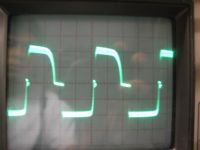
At present I am having some problems with the UD1.3 driver... After finally locating a solder blob bridging two pins of a MOSFET, I get a full +/- 20V swing on the GDT secondary (I subtituted a 20V power regulator instead of Ward's 24V one), but the waveform seems to contain some really high frequency ringing (?) which makes the traces look really thick, and something is wrong with the rising edge:
(10V/div, 20µs/div)

The P-channel mosfets heat up quite a bit (especially Q3) although the connections and orientation appears to be correct. Also I hear a high pitched noise when running the circuit... The schematic can be found here
I am using a 555 square wave generator for feedback at 5V and around 10kHz.
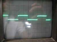
Here is the gate waveform to one of the N channel MOSFETs:

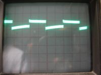
To the P channel MOSFETs (via DC-blocking(?) capacitor)

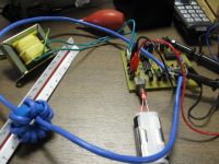
Setup:

Any suggestions would be greatly appreciated!
bob800, Mon Sept 01 2014, 09:30PM
Thanks for the suggestions! I'll use the nylon bolt method...
At present I am having some problems with the UD1.3 driver... After finally locating a solder blob bridging two pins of a MOSFET, I get a full +/- 20V swing on the GDT secondary (I subtituted a 20V power regulator instead of Ward's 24V one), but the waveform seems to contain some really high frequency ringing (?) which makes the traces look really thick, and something is wrong with the rising edge:
(10V/div, 20µs/div)

The P-channel mosfets heat up quite a bit (especially Q3) although the connections and orientation appears to be correct. Also I hear a high pitched noise when running the circuit... The schematic can be found here
I am using a 555 square wave generator for feedback at 5V and around 10kHz.
Here is the gate waveform to one of the N channel MOSFETs:

To the P channel MOSFETs (via DC-blocking(?) capacitor)

Setup:

Any suggestions would be greatly appreciated!
Re: First DRSSTC -- questions
bob800, Sat Sept 06 2014, 12:33AM
Any thoughts?... In all my projects so far I've never seen a waveform like the first one I posted, in terms of trace thickness and weird dead-time differences, so I'm at a loss as to what would could be causing it.
I've spent many hours troubleshooting the circuit and would appreciate any feedback about the waveforms!
EDIT: Well I checked over the PCB connections again and noticed that one of the diode pins simply wasn't soldered properly... (the diode connected to the gate signal for the P mosfets). After resoldering, the edges of the waveform looked normal, but the ringiness/trace thickness was still apparent and the MOSFETs still hot.
I tried swapping the GDT for a differnent one, and using a faster 555 feedback signal (to increase reactance), and everything looks OK now! Just some under/over shoots but hopefully the IGBT gate zeners should take care of that.
Print this page