DC Power source
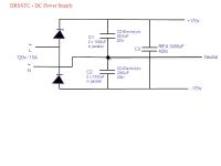
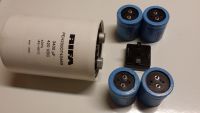
Graham Armitage, Thu Jul 10 2014, 01:25AMI wanted to run a power source config past the experts. Using caps I already have I hoped that I could create the voltage doubler with smaller electrolytics and use the quality RIFA tightly mounted to the IGBT. I think this configuration works but would welcome any thoughts or concerns before I build it.
C1 and C2 are Cornell-Dublier 1000uF/200V electrolytics in parallel to give 2000uF at 200v across each branch of the doubler and to provide smoothing. The RIFA 3400uF will then provide the reservoir for pulse discharge and additional smoothing.


Input current draw should be less than 15A for this coil - the rectifier is rated for 35A.
Re: DC Power source
Steve Ward, Thu Jul 10 2014, 06:09AM
Should work fine.
Steve Ward, Thu Jul 10 2014, 06:09AM
Should work fine.
Re: DC Power source
Graham Armitage, Thu Jul 10 2014, 01:26PM
I couldn't ask for more expert opinion than that. No offense to all the other experts !
Thanks Steve
Graham Armitage, Thu Jul 10 2014, 01:26PM
I couldn't ask for more expert opinion than that. No offense to all the other experts !
Thanks Steve
Re: DC Power source
Dr. Dark Current, Thu Jul 10 2014, 06:54PM
Just make sure the doubler caps are rated for the rms input current (consider power factor). Other than that, there are no more problems.
Dr. Dark Current, Thu Jul 10 2014, 06:54PM
Just make sure the doubler caps are rated for the rms input current (consider power factor). Other than that, there are no more problems.
Re: DC Power source
Graham Armitage, Fri Jul 11 2014, 11:03AM
I can't find anything on RMS current rating (just voltage). The specs I have only show ripple current of 2.8A for each cap.
Graham Armitage, Fri Jul 11 2014, 11:03AM
I can't find anything on RMS current rating (just voltage). The specs I have only show ripple current of 2.8A for each cap.

Re: DC Power source
Steve Conner, Fri Jul 11 2014, 11:53AM
Well, with 15A RMS input you are putting 10.6A RMS through each branch of the doubler, thus 5.3A RMS in each individual capacitor.
That's almost twice the datasheet ripple current rating (which is RMS) but for intermittent duty in a Tesla coil, you should get away with it easily. The datasheet rating allows the cap to pass that current continuously in a high ambient temperature for something like 2000 hours before it dries out.
Re: DC Power source
Graham Armitage, Fri Jul 11 2014, 11:58AM
ok - that makes sense. Thanks for the explanation. I will give it a try and if I let the smoke out I will get some better caps
Graham Armitage, Fri Jul 11 2014, 11:58AM
ok - that makes sense. Thanks for the explanation. I will give it a try and if I let the smoke out I will get some better caps

Re: DC Power source
HV Enthusiast, Fri Jul 11 2014, 01:05PM
I would also add some bleeders across the capacitors which will act as balancing resistors as well, but argubly not required.
But the bleeders are important for safety. I usually size mine to be able to discharge the full stack in 5 minutes. This is usually just a 20k, 5W resistor across each capacitor for a 340VDC total bus voltage.
Re: DC Power source
Graham Armitage, Fri Jul 11 2014, 01:11PM
Absolutely agree. I followed that from your minibrute design I built and it's great to know that those caps are discharging when you power down. It's an essential safety feature IMO. If I remember correctly I used 10W/6k resistors for the minibrute coil and that worked well too.
Re: DC Power source
Antonio, Fri Jul 11 2014, 01:15PM
Put LEDs in series with the bleeding resistors. You can then see if it's safe to touch the circuit and if it is working correctly.
Antonio, Fri Jul 11 2014, 01:15PM
Put LEDs in series with the bleeding resistors. You can then see if it's safe to touch the circuit and if it is working correctly.
Re: DC Power source
Graham Armitage, Fri Jul 11 2014, 01:18PM
That's a great suggestion. Thanks
Graham Armitage, Fri Jul 11 2014, 01:18PM
Antonio wrote ...
Put LEDs in series with the bleeding resistors. You can then see if it's safe to touch the circuit and if it is working correctly.
Put LEDs in series with the bleeding resistors. You can then see if it's safe to touch the circuit and if it is working correctly.
That's a great suggestion. Thanks
Re: DC Power source
Mads Barnkob, Fri Jul 11 2014, 08:31PM
Take a sound advise from heavy industry, if you use light off for safe state, use two separate lamps in parallel, you do not want to think your circuit is safe just because a lamp failed.
This is why normal state of signalling lamps offshore is light always on and unsafe is light blinking.
Mads Barnkob, Fri Jul 11 2014, 08:31PM
Graham Armitage wrote ...
That's a great suggestion. Thanks
Antonio wrote ...
Put LEDs in series with the bleeding resistors. You can then see if it's safe to touch the circuit and if it is working correctly.
Put LEDs in series with the bleeding resistors. You can then see if it's safe to touch the circuit and if it is working correctly.
That's a great suggestion. Thanks
Take a sound advise from heavy industry, if you use light off for safe state, use two separate lamps in parallel, you do not want to think your circuit is safe just because a lamp failed.
This is why normal state of signalling lamps offshore is light always on and unsafe is light blinking.
Re: DC Power source
Steve Conner, Sat Jul 12 2014, 04:56PM
I prefer neon lamps, they look more ominous than LEDs.
I wouldn't put things in series with the bleeder resistors either. If one of the LEDs comes loose, not only do you lose the high voltage warning, but you lose the bleeder resistor and the high voltage lurks around for longer.
I also spent some time thinking about the issue Mads mentioned. My solution was to add an analog voltmeter permanently wired to the DC bus. It serves as a backup to the warning lamps and also does something useful in its own right.
Steve Conner, Sat Jul 12 2014, 04:56PM
I prefer neon lamps, they look more ominous than LEDs.

I wouldn't put things in series with the bleeder resistors either. If one of the LEDs comes loose, not only do you lose the high voltage warning, but you lose the bleeder resistor and the high voltage lurks around for longer.
I also spent some time thinking about the issue Mads mentioned. My solution was to add an analog voltmeter permanently wired to the DC bus. It serves as a backup to the warning lamps and also does something useful in its own right.
Re: DC Power source
Thomas W, Sat Jul 12 2014, 05:23PM
I would personally not have 5 minutes as im impatient. I would suggest a 10 second discharge though a high wattage resistor, not long enough to damage it. Use a contactor that is Normally Closed so when the circuit is not being powered from the socket, its being dumped and the resistor isn't connected when its being used, saving a tiny amount of electricity.
Re: DC Power source
Graham Armitage, Sat Jul 12 2014, 07:24PM
Seems to be two threads in one here - one around the visual aspect and the other around the actual discharge. I tend to be impatient too and 5 mins would probably not work for me. I did have a relay that was normally closed with high wattage resistors and they would rapidly bleed the caps when power was turned off. That worked great until a strike to the primary fried it (they are not cheap). i don't mind a steady trickle bleed while in operation if I know it will passively start dropping the voltage as soon as I power down.
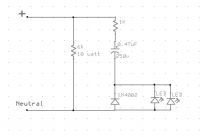
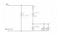
As Steve suggests, it's not good to have anything in series with the bleeder resistor, would this circuit work as an indicator? 2 LEDs for extra safety.

Ooops - LED's won't light up if they're wired that way. This should be better...

Graham Armitage, Sat Jul 12 2014, 07:24PM
Seems to be two threads in one here - one around the visual aspect and the other around the actual discharge. I tend to be impatient too and 5 mins would probably not work for me. I did have a relay that was normally closed with high wattage resistors and they would rapidly bleed the caps when power was turned off. That worked great until a strike to the primary fried it (they are not cheap). i don't mind a steady trickle bleed while in operation if I know it will passively start dropping the voltage as soon as I power down.
As Steve suggests, it's not good to have anything in series with the bleeder resistor, would this circuit work as an indicator? 2 LEDs for extra safety.

Ooops - LED's won't light up if they're wired that way. This should be better...

Re: DC Power source
johnf, Sat Jul 12 2014, 07:52PM
no!!
that circuit seems to be random components put down on paper.
for a start the DC rail should be + and minus not neutral.
The capacitor stops all dc from flowing so no leds will light. the leds are in backwards.
There is no need for the diode in fact its inclusion will make sure the leds will not light
I'm susre there are still more mistakes
Re: DC Power source
Graham Armitage, Sat Jul 12 2014, 09:45PM
Correct - will not work. I realized after posting - I pulled it from another circuit, but that was an AC source in which case I believe it does work. Scratch that for the rectified DC supply.
Graham Armitage, Sat Jul 12 2014, 09:45PM
Correct - will not work. I realized after posting - I pulled it from another circuit, but that was an AC source in which case I believe it does work. Scratch that for the rectified DC supply.
Print this page