
+/- 30 kV(60 kV) LAB HV powersupply with custom flyback transformers, variable
Erlend^SE, Mon Feb 03 2014, 08:30PMHi
I am going to build a +30 kV and -30 kV variable supply.
Currently I am negotiating details with someone who can make the transformers.
(if others want the transformers too, please tell.. it helps in getting volume discounts)
Transformer:
OEM/Special "flyback" pair (one +30 kV, the other -30 kV), probably driven in half-bridge.
Built in temperature sensor
Voltage feedback (via internal resistor)
Current sensing (external, on board)
Shielded 2 meter output cable (shield is grounded)
5 mA output (will ask more around)
Primary: 2x12V (for 12/24V supply)
Driver:
TL494 with FET-driver if I am going for half-bridge, UC3842 if I am going for flyback instead.
May look into more common parts given they can do high+low side FET drive.
Other:
Microcontroller to set and messure current limits and voltages.
RS485 link for computer control (also useful for whatever other aux board I decide to use, related or not)
Added:
Transformer schematic (round ones):

Picture of transformers before shipping:

Update:
Getting near actual high voltage test:

Ethernet link works, just need to do way more software on computer and microcontroller.
Re: +/- 30 kV(60 kV) LAB HV powersupply with custom flyback transformers, variable
Thomas W, Mon Feb 03 2014, 09:37PM
I would be interested in such transforemrs, but im looking for around 3kW on each one, 30Kv @ 100mA pity your one is so much less >_<
But a very interesting project, i shall be following this with great intrest.
Thomas W, Mon Feb 03 2014, 09:37PM
I would be interested in such transforemrs, but im looking for around 3kW on each one, 30Kv @ 100mA pity your one is so much less >_<
But a very interesting project, i shall be following this with great intrest.
Re: +/- 30 kV(60 kV) LAB HV powersupply with custom flyback transformers, variable
Sulaiman, Tue Feb 04 2014, 03:51PM
I suspect that over time the eht cables will get shorter and shorter due to different terminations, and are bulky/messy when not in use.
If possible/economical, eht terminals/connectors may be better.
To be able to 'play' or experiment at early stages of testing safely,
try to minimise or make switchable the output capacitance.
doesn't take much capacitance at +/- 30 kV to destroy components or give one heck of a shock !
build in a 'discharge' system
adding a high value/voltage resistance in series with a neon
(neon at 0v side, resistor to eht side is easier)
across each output gives a visual 'caution' indicator and a small load to make output voltage regulation easier at light loads.
(e.g. 10 x 3.5 kV rated 33 MOhm in series = 330 MOhm = 100uA @ 33kV = max. neon current)
Re: +/- 30 kV(60 kV) LAB HV powersupply with custom flyback transformers, variable
Erlend^SE, Tue Feb 04 2014, 04:42PM
I am looking for some standoffs, maybe the "suction cup" of TV type over the ends joining some HV "outlet".
It won't be able to hold a voltage once input power is lost.
THere won't be any unshielded voltages above 48V or so near the controller.
Erlend^SE, Tue Feb 04 2014, 04:42PM
Sulaiman wrote ...
I suspect that over time the eht cables will get shorter and shorter due to different terminations, and are bulky/messy when not in use.
If possible/economical, eht terminals/connectors may be better.
Yep, will have to figure out some connection box, but 2 meters cables give some safety distance from supply.I suspect that over time the eht cables will get shorter and shorter due to different terminations, and are bulky/messy when not in use.
If possible/economical, eht terminals/connectors may be better.
I am looking for some standoffs, maybe the "suction cup" of TV type over the ends joining some HV "outlet".
Sulaiman wrote ...
To be able to 'play' or experiment at early stages of testing safely,
try to minimise or make switchable the output capacitance.
doesn't take much capacitance at +/- 30 kV to destroy components or give one heck of a shock !
I plan to have no output capacitance added, anyway, the cable is with grounded shielding so laying the cable over stuff should be no problem.To be able to 'play' or experiment at early stages of testing safely,
try to minimise or make switchable the output capacitance.
doesn't take much capacitance at +/- 30 kV to destroy components or give one heck of a shock !
Sulaiman wrote ...
build in a 'discharge' system
adding a high value/voltage resistance in series with a neon
(neon at 0v side, resistor to eht side is easier)
across each output gives a visual 'caution' indicator and a small load to make output voltage regulation easier at light loads.
(e.g. 10 x 3.5 kV rated 33 MOhm in series = 330 MOhm = 100uA @ 33kV = max. neon current)
Actually, the transformer will have a 300 MOhm resistor internally, and I plan to mostly do powered on discharge (monitor voltage as it goes down)build in a 'discharge' system
adding a high value/voltage resistance in series with a neon
(neon at 0v side, resistor to eht side is easier)
across each output gives a visual 'caution' indicator and a small load to make output voltage regulation easier at light loads.
(e.g. 10 x 3.5 kV rated 33 MOhm in series = 330 MOhm = 100uA @ 33kV = max. neon current)
It won't be able to hold a voltage once input power is lost.
THere won't be any unshielded voltages above 48V or so near the controller.
Re: +/- 30 kV(60 kV) LAB HV powersupply with custom flyback transformers, variable
Sulaiman, Tue Feb 04 2014, 04:53PM
The cheapest eht connectors that I have seen are modified automotive spark plugs.
Ceramic eht terminals can be cheap or insanely expensive on eBay.
Re. output capacitance;
- none = voltage ripple
- stored energy at 31.6 kV = 0.5 mJ per pF (cable etc.) = ouch!
'pro' looking is a key switch to enable
and a 'trip' circuit break-to-operate,
e.g. hold a n.o. button switch to maintain power, or don't break a thin wire 'barrier' etc.
NOT electronically but electro-mechanically where practical.
e.g. auxiliary isolated low voltage supply (ac or dc)
to a suitable relay coil in series with keyswitch and 'loop' terminals.
could be screw terminals or 3.5mm jack etc.
normally open Relay contacts in series with output stage power etc..
Re: +/- 30 kV(60 kV) LAB HV powersupply with custom flyback transformers, variable
Erlend^SE, Tue Mar 11 2014, 08:46PM
Update:
Internal resistor: 300 Mega-ohm - confirmed
Output current: 10 mA @ 30 kV (300W per transformer) - confirmed
System max voltage into isolated load: 60 kV (dual transformer, 600W) - by design
Driver topology: 30 KHz half-bridge flyback driver (need to figure out the deal with it)
Seller: really helpful
Transformer got built in temperature sensor.
The PCB itself won't have voltages above 30V (safe to touch), input is 12V or 24V.
Made the purchase, agreed on transformer casing/shell type, windings, PCB mounting via through hole.
Re: +/- 30 kV(60 kV) LAB HV powersupply with custom flyback transformers, variable
Andy, Thu Apr 17 2014, 11:07PM
Hi Erlend^SE
Hows the project going? Would we be able to have a diagram of the circuit?
Thanks
Andy, Thu Apr 17 2014, 11:07PM
Hi Erlend^SE
Hows the project going? Would we be able to have a diagram of the circuit?
Thanks
Re: +/- 30 kV(60 kV) LAB HV powersupply with custom flyback transformers, variable
Erlend^SE, Wed Apr 23 2014, 09:45PM
Erlend^SE, Wed Apr 23 2014, 09:45PM
Re: +/- 30 kV(60 kV) LAB HV powersupply with custom flyback transformers, variable
Erlend^SE, Mon Oct 26 2015, 09:58PM
Hi
Getting close to getting my board-design order-able.
I have decided to go for H-bridge driver and microcontroller PWM.
I may have failed to keep it simple!

Erlend^SE, Mon Oct 26 2015, 09:58PM
Hi
Getting close to getting my board-design order-able.
I have decided to go for H-bridge driver and microcontroller PWM.
I may have failed to keep it simple!

Re: +/- 30 kV(60 kV) LAB HV powersupply with custom flyback transformers, variable
Sulaiman, Mon Oct 26 2015, 10:15PM
MAY have failed to keep it simple ?
WOW !
that looks like a nicely designed pcb.
I hope that it performs as good as it looks ... great.
Sulaiman, Mon Oct 26 2015, 10:15PM
MAY have failed to keep it simple ?
WOW !
that looks like a nicely designed pcb.
I hope that it performs as good as it looks ... great.
Re: +/- 30 kV(60 kV) LAB HV powersupply with custom flyback transformers, variable
Patrick, Fri Dec 04 2015, 10:04PM
I want to see how well this works out, I'm rebuilding mine :

Patrick, Fri Dec 04 2015, 10:04PM
I want to see how well this works out, I'm rebuilding mine :

Re: +/- 30 kV(60 kV) LAB HV powersupply with custom flyback transformers, variable
Erlend^SE, Sat Dec 05 2015, 12:43AM
Note: my supply will fit within 10x15 (base) x15 (tall) cm (not including cables)
I have ordered the board, so getting somewhere.
Will have to do a multi-component order to get the other parts needed.
I wonder about building a HV isolator based on spinning wheel of capacitors, so I can get 60 kV isolated.
Board will be managed from UART control panel (not designed) or Ethernet control from computer. (also added RS232 & RS485)
Erlend^SE, Sat Dec 05 2015, 12:43AM
Patrick wrote ...
I want to see how well this works out, I'm rebuilding mine :
I want to see how well this works out, I'm rebuilding mine :
Note: my supply will fit within 10x15 (base) x15 (tall) cm (not including cables)
I have ordered the board, so getting somewhere.
Will have to do a multi-component order to get the other parts needed.
I wonder about building a HV isolator based on spinning wheel of capacitors, so I can get 60 kV isolated.
Board will be managed from UART control panel (not designed) or Ethernet control from computer. (also added RS232 & RS485)
Re: +/- 30 kV(60 kV) LAB HV powersupply with custom flyback transformers, variable
Erlend^SE, Thu Dec 31 2015, 07:12PM
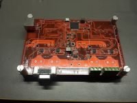
Test-fitted the components loosely, no soldering so far.
Seems to fit nicely together

Just put RJ45 jack (ethernet), DSub (rs232), power input (screw terminals) in place. Looking good.
Erlend^SE, Thu Dec 31 2015, 07:12PM
Test-fitted the components loosely, no soldering so far.
Seems to fit nicely together

Just put RJ45 jack (ethernet), DSub (rs232), power input (screw terminals) in place. Looking good.
Re: +/- 30 kV(60 kV) LAB HV powersupply with custom flyback transformers, variable
woodchuck, Thu Dec 31 2015, 07:57PM
I'm following this with great interest. Love what you've done to date!
So you were driving the transformer at 30 kHz when you obtained 10 mA @ 30 kV? Is the maximum frequency somewhat limited by parasitic capacitance of secondary?
woodchuck, Thu Dec 31 2015, 07:57PM
I'm following this with great interest. Love what you've done to date!
So you were driving the transformer at 30 kHz when you obtained 10 mA @ 30 kV? Is the maximum frequency somewhat limited by parasitic capacitance of secondary?
Re: +/- 30 kV(60 kV) LAB HV powersupply with custom flyback transformers, variable
Patrick, Mon Jan 04 2016, 05:22PM
how do you know its 10mA ?
Patrick, Mon Jan 04 2016, 05:22PM
how do you know its 10mA ?
Re: +/- 30 kV(60 kV) LAB HV powersupply with custom flyback transformers, variable
Erlend^SE, Mon Jan 04 2016, 05:26PM
1. the transformers on that board is 3.3 mA, the other ones are 10 mA.
2. they are made to order to do 10 mA (blocks)/3.3 mA (round ones).
Erlend^SE, Mon Jan 04 2016, 05:26PM
1. the transformers on that board is 3.3 mA, the other ones are 10 mA.
2. they are made to order to do 10 mA (blocks)/3.3 mA (round ones).
Re: +/- 30 kV(60 kV) LAB HV powersupply with custom flyback transformers, variable
Erlend^SE, Tue Mar 29 2016, 08:57PM
Progress:
Soldered on the logic + internal voltage regulators & FET's and drivers(not transformers yet).
Ethernet seems to work (ordering a genuine chip, seems like the ENC424J600 chips from aliexpress is junk)
Gate waveform looks good (low side only tested, no voltage on bridge)
Got to code some kind of data-logging before taking it live!
Re: +/- 30 kV(60 kV) LAB HV powersupply with custom flyback transformers, variable
Erlend^SE, Sat Apr 02 2016, 01:49PM
Pictures of board as of how it currently is here.
Waiting for a shipment of parts expected to arrive next week, then I should be able to get Ethernet up & running.
Next is code tuning, and transformer testing (with spark-gap)

Erlend^SE, Sat Apr 02 2016, 01:49PM
Pictures of board as of how it currently is here.
Waiting for a shipment of parts expected to arrive next week, then I should be able to get Ethernet up & running.
Next is code tuning, and transformer testing (with spark-gap)


Re: +/- 30 kV(60 kV) LAB HV powersupply with custom flyback transformers, variable
Vale, Sun Apr 03 2016, 09:02AM
Looks neat, what's with the large jumper and smd button on that ic?
Vale, Sun Apr 03 2016, 09:02AM
Looks neat, what's with the large jumper and smd button on that ic?
Re: +/- 30 kV(60 kV) LAB HV powersupply with custom flyback transformers, variable
Erlend^SE, Sun Apr 03 2016, 10:24AM
It's actually a 25 MHz crystal for ethernet. I didn't have the right shape.
It will be replaced with a crystal that fits, as soon as I get the package I am waiting for. (Next week)
Erlend^SE, Sun Apr 03 2016, 10:24AM
It's actually a 25 MHz crystal for ethernet. I didn't have the right shape.
It will be replaced with a crystal that fits, as soon as I get the package I am waiting for. (Next week)
Re: +/- 30 kV(60 kV) LAB HV powersupply with custom flyback transformers, variable
Patrick, Sun Apr 03 2016, 05:12PM
can we get a peek at the voltage feed back schematic ?
Patrick, Sun Apr 03 2016, 05:12PM
can we get a peek at the voltage feed back schematic ?
Re: +/- 30 kV(60 kV) LAB HV powersupply with custom flyback transformers, variable
Erlend^SE, Sun Apr 03 2016, 05:57PM
Sure,
but it's basically a internal 300 MOhm resistor, combined with a 2 kohm external resistor to ground(or other known voltage).
The resistor circuit converts 0-30 kV into 0-2V, that can then be meassured by a microcontroller.
I can PM you the schematic (or even design files) if you want, but the circuit for the whole board is somewhat big).
be warned: If you are not used to op-amps, the op-amp signal buffers is likely to confuse you.
Re: +/- 30 kV(60 kV) LAB HV powersupply with custom flyback transformers, variable
Patrick, Sun Apr 03 2016, 08:42PM
ok a simple voltage divider with op-amp. so do you have a capacitor on the HV side ?
Patrick, Sun Apr 03 2016, 08:42PM
ok a simple voltage divider with op-amp. so do you have a capacitor on the HV side ?
Re: +/- 30 kV(60 kV) LAB HV powersupply with custom flyback transformers, variable
Erlend^SE, Sun Apr 03 2016, 08:47PM
Well.. both yes & no
There is no HV capacitor in the transformer itself, but the output cable is shielded with grounded shield.
And it's unavoidable that the cable will work as output capacitor, so I plan to use it to my advantage. Cutting the cable down in length is out of question!
The op-amp is just voltage follower, it should have zero effect on the divider itself, but gives the signal to the rest of the board (microcontroller) lower impedance.
My transformers are made for 12/24V bridge, but most other transformers are designed to run in flyback from something in the 70-150V range, with a 1000V-1500V transistor.
Erlend^SE, Sun Apr 03 2016, 08:47PM
Patrick wrote ...
ok a simple voltage divider with op-amp. so do you have a capacitor on the HV side ?
ok a simple voltage divider with op-amp. so do you have a capacitor on the HV side ?
Well.. both yes & no
There is no HV capacitor in the transformer itself, but the output cable is shielded with grounded shield.
And it's unavoidable that the cable will work as output capacitor, so I plan to use it to my advantage. Cutting the cable down in length is out of question!
The op-amp is just voltage follower, it should have zero effect on the divider itself, but gives the signal to the rest of the board (microcontroller) lower impedance.
My transformers are made for 12/24V bridge, but most other transformers are designed to run in flyback from something in the 70-150V range, with a 1000V-1500V transistor.
Re: +/- 30 kV(60 kV) LAB HV powersupply with custom flyback transformers, variable
Proud Mary, Mon May 30 2016, 07:17PM
Many designers tasked to produce a 30 kV@10mA supply would choose to have the 30 kV tripled up from a 10 kV secondary, and I wondered why you had chosen not to do this.
Proud Mary, Mon May 30 2016, 07:17PM
Many designers tasked to produce a 30 kV@10mA supply would choose to have the 30 kV tripled up from a 10 kV secondary, and I wondered why you had chosen not to do this.
Re: +/- 30 kV(60 kV) LAB HV powersupply with custom flyback transformers, variable
Erlend^SE, Mon May 30 2016, 08:43PM
Mostly since I don't want a circuit with all those capacitors.
Also, it would take quite some isolation, and that can be messy.
I just want a tiny power-supply module, that is very controllable.
Erlend^SE, Mon May 30 2016, 08:43PM
Proud Mary wrote ...
Many designers tasked to produce a 30 kV@10mA supply would choose to have the 30 kV tripled up from a 10 kV secondary, and I wondered why you had chosen not to do this.
Many designers tasked to produce a 30 kV@10mA supply would choose to have the 30 kV tripled up from a 10 kV secondary, and I wondered why you had chosen not to do this.
Mostly since I don't want a circuit with all those capacitors.
Also, it would take quite some isolation, and that can be messy.
I just want a tiny power-supply module, that is very controllable.
Print this page