Calculating LTR
Hazmatt_(The Underdog), Mon Sept 11 2006, 12:59AMI'm taking a look at all the details in greater scrutiny then what I probably should be, but the issue is I want to know that what I am doing is efficient. I am also trying to expand and improve SGTC's with a wealth of information glossed over by most Coiler's.
Insted of using a correction factor, I want to know what is the reasoning behind LTR, and I have some answers for all of you, but this will mean a lot of work on your part to solve your particular problem.
Here we have the extracted equavilent circuit of a 9000VAC 120mA NST as the source for a nasty Tesla Coil I am designing for C.S.U.L.B. This system needs to be efficient and effective because of portability, power, cost, and other factors.
As you can see from the system I have performed the load/unloaded tests to find all the related characteristics from the transformer. The details for this can be found on our local Wiki.
In playing with the transformer we find the resonant charging defined from Z = E/I.
9000 VAC / 120mA = 75000
And to find the resonant Capacitor value we have simply
Z = 1/(2piFZ) = 35.4nF at 60Hz.
This is a good start, but not our LTR value. So what exactly is a proper LTR value?
Let us consider only the inductive component of the Transformer now as something critical. This value can be seen on the schematic as 61H. This is the extracted inductance of the transformer during power on. It is not the measured static inductance of the core. These two inductances vary greatly. If you attempted to measure the inductance of the secondary windings you would find that the inductance of this transformer is ~200H per coil, no where near the 61H powered-on.
So let us consider the reactive component: XL = 2piFL = 23000
And the Resistive component = 17000
Taking the magnitude of the two gives us our Zbranch equavilent of 28600, but lets consider it to be 28000 to be conservative.
Subtracting our Z from XL gives us: 75000-28000 = 47000 = Z'
Now Z' is our impedance of our system that the transformer should be matched to the capacitor. Lets see what the value is
C = 1/2piFZ' = 51nF Wow! our LTR Value.
Now lets go to simulation to see how this matches up and see if our predictions are true.
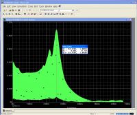
You can see in the graph that the power distribution is pretty accurate and gives a region of 1100W in the capacitor. This is critical because a correction factor may not approximate the actual inductances and losses inherent in a given transformer.
To do this analysis on a transformer requires a Wattmeter. I bought one from Extech for about $200 USD. Simply loading the transformer is not good enough because you need the power factor for the analysis. The clamp-on wattmeter gives you power factor.


Re: Calculating LTR
Terry Fritz, Mon Sept 11 2006, 04:47AM
Hi,
Many folks knew that Larger Than Resonant cap values did good things but it was not until computer analysis with MicroSim that it became well understood.
It has been a long time but there are some resources that might help in your quest:
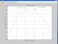
This is the first analysis ever done that shows the LTR Static gap values poping up:

I did all that by hand one model at a time The excel file has data for many NSTs in it.
Note these papers from Tero Ranta:

I used models like this a lot:

There is this design chart:

The archives of have most of the details:

This might be what you seek:

Note that static gap and sync gap coils are significantly different. Static gap coils need a voltage fired switch like is used here:

Sync gap coils need the gap timing "scaned" to find the optimal firing point (typically "after" the AC peak). LTR coils have lower NST voltage unitl they start to fire and the voltage "kicks up".
You will want PFC caps on the NST input to correct the power factor for sure!
BTW - A very nice $30 watt meter is here:


I am not connected to The Meter Guy but he referenced my test report on the Kill-A-Watt.
In your schematic model, you show the streamer load as like 50pF at 2000M. That is way off. Should be 220K for the resistance and:
Cl = (terminal diameter - expected streamer length) / 2 pF/inch
So a 6 x 24 toroid with 30 inch sparks gives a streamer load of 220k ohms plus 12pF.
Hope this helps.
Cheers,
Terry
Terry Fritz, Mon Sept 11 2006, 04:47AM
Hi,
Many folks knew that Larger Than Resonant cap values did good things but it was not until computer analysis with MicroSim that it became well understood.
It has been a long time but there are some resources that might help in your quest:
This is the first analysis ever done that shows the LTR Static gap values poping up:

I did all that by hand one model at a time
 The excel file has data for many NSTs in it.
Note these papers from Tero Ranta:

I used models like this a lot:

There is this design chart:

The archives of
 have most of the details:
This might be what you seek:

Note that static gap and sync gap coils are significantly different. Static gap coils need a voltage fired switch like is used here:

Sync gap coils need the gap timing "scaned" to find the optimal firing point (typically "after" the AC peak). LTR coils have lower NST voltage unitl they start to fire and the voltage "kicks up".
You will want PFC caps on the NST input to correct the power factor for sure!
BTW - A very nice $30 watt meter is here:


I am not connected to The Meter Guy but he referenced my test report on the Kill-A-Watt.
In your schematic model, you show the streamer load as like 50pF at 2000M. That is way off. Should be 220K for the resistance and:
Cl = (terminal diameter - expected streamer length) / 2 pF/inch
So a 6 x 24 toroid with 30 inch sparks gives a streamer load of 220k ohms plus 12pF.
Hope this helps.
Cheers,
Terry
Re: Calculating LTR
Hazmatt_(The Underdog), Mon Sept 11 2006, 07:12AM
Tero Ranta says that there is no likely way to predict the size of the LTR cap. Well, my method pretty much nailed it as far as I know.
I don't have time right now to check a 12/60 and verify a second time, but I will sometime.
I am posting this because the simulation verified this simple calculation well, provided you took the time to extract/calculate your transformer characteristics.
I will go back and adjust the secondary circuit when I am at that phase. We still do not as of yet really have the secondary wound. Pri/Sec considerations are ballpark for test sim. The majority of the system is devoted to determine optimal capacitor, line filter, and gap electrodes (as worst case).
I have found that 2nF as your protection capacitors do not provide nearly enough protection, that is why they are sized to 10pF each. When I ran the simulations I was shocked how little even a 470pF capacitor protects the transformer.
More to come in time.
Matt
Re: Calculating LTR
IamSmooth, Thu Nov 16 2006, 06:41PM
I have the ability to measure the R and XL components of my transformer during power-on. Are you measuring the secondary or primary coil? Does it matter which one you measure?
IamSmooth, Thu Nov 16 2006, 06:41PM
Hazmatt_(The Underdog) wrote ...
So let us consider the reactive component: XL = 2piFL = 23000
And the Resistive component = 17000
So let us consider the reactive component: XL = 2piFL = 23000
And the Resistive component = 17000
I have the ability to measure the R and XL components of my transformer during power-on. Are you measuring the secondary or primary coil? Does it matter which one you measure?
Re: Calculating LTR
Hazmatt_(The Underdog), Thu Nov 16 2006, 09:31PM
It absolutely matters what coil you measure and how you measure it. The primary of a NST has a much lower branch impedance then the secondary branch impedance, also the secondary has 2 branch impedances.
The transformer was measured using the load and no-load tests, with a wattmeter so I could find the VA and phase. I wrote up an example for the wiki so others could take measurements and simulate, calculate, etc. their systems for performance and tweaking.
Getting your transformer parameters can be a real job, but I hope the examples are helpful:

Matt
Hazmatt_(The Underdog), Thu Nov 16 2006, 09:31PM
It absolutely matters what coil you measure and how you measure it. The primary of a NST has a much lower branch impedance then the secondary branch impedance, also the secondary has 2 branch impedances.
The transformer was measured using the load and no-load tests, with a wattmeter so I could find the VA and phase. I wrote up an example for the wiki so others could take measurements and simulate, calculate, etc. their systems for performance and tweaking.
Getting your transformer parameters can be a real job, but I hope the examples are helpful:

Matt
Print this page