
My school coilgun poject
Skynet, Tue Nov 12 2013, 02:47PMHi all,
at first i apologize for my english (I´m fom Czech republic)
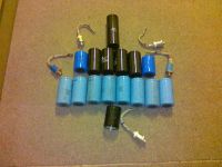
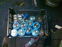
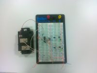
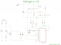
So few weeks ago i started to work on my school project i gathered some big caps, IGBTs and SCRs. And last week i finished my triggering circuit. Also you can have questions on me

I would post to this thread progress of my wok

Re: My school coilgun poject
Skynet, Mon Jan 20 2014, 02:10PM
A small update here.
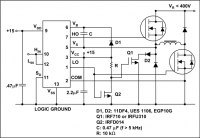
1. I updated a half bridge switching of coil according to application notes
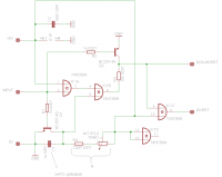
2. I created a logic that responds to output pulses from the optical gate. Pulses that are longer than 1ms are reduced to 1 ms and pulses that are shorter than 1ms leaves shorter. That prevents to damage of my IGBTS
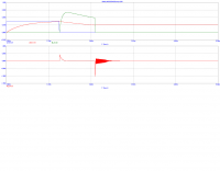
3. I created a simulation with realistic parameters components, where I tried to simulate circuit when the current is switched.
C=4700uF
L=30uH
U=450V
Now there was only to conect everything together and make the test. It would by probably next week becauce I have exams this week.
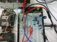
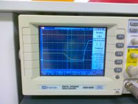
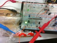
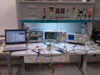
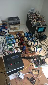
The last photos are from the lab where I measured the total circuit delay and testing a new barrel.


Re: My school coilgun poject
Yandersen, Mon Jan 20 2014, 08:57PM
Finally some halfbridge is being made here. Good job, Skynet, I keep my fingers crossed for your success! :)
Yandersen, Mon Jan 20 2014, 08:57PM
Finally some halfbridge is being made here. Good job, Skynet, I keep my fingers crossed for your success! :)
Re: My school coilgun poject
Skynet, Tue Jan 28 2014, 07:50PM
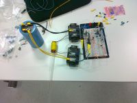
Just a small photo update of progress I´ll probably test it tomorow
So today I made some tests...
At first at 150V with 25ms pulse it worked perfectly:
Then I increased the voltage to 250V. Everything looked good, but then IR2113 started smoking.
These parts were destroyed, and I do not know why. Could anyone advise me what could have happened.

Skynet, Tue Jan 28 2014, 07:50PM
Just a small photo update of progress
 I´ll probably test it tomorow

So today I made some tests...
At first at 150V with 25ms pulse it worked perfectly:
Then I increased the voltage to 250V. Everything looked good, but then IR2113 started smoking.
These parts were destroyed, and I do not know why. Could anyone advise me what could have happened.

Re: My school coilgun poject
Yandersen, Sun Feb 02 2014, 03:45PM
1) The circuit like yours I see first time. As you did not specified the IC used, I thought that sch is some IC-specific one, because I do not clearly understand the purpose of R,Q1,Q2,D2. Please, post IC part number and explain the schematic. I guess, you are trying to hold Vs pin at the ground level until the shot. But because of R the closing time of Q1 will be delayed, so when High IGBT got opened, Q1 may still be somewhat conductive and may burn causing chain reaction for all other elements. Replace all this BS with a 100K resistor between ground and Vs.
2) The breadboard you use may let contacts shake, especially due to vibrations during the shot. That may have cause the problem. Use the soldering tool to connect all elements in the circuit.
3) 25ms is a way too long pulse. Drop it down to 10ms at most.
4) If you time the shot with a 555 or 556 timer IC, be aware that those devices are very sensitive - they may glitch and trigger due to any noise on the supply rails. I also suspect my 556 timers to react even on EMI caused by switching of the coils, but I may be wrong.
Re: My school coilgun poject
Skynet, Mon Feb 03 2014, 02:43PM
I use IR2113 driver => http://www.irf.com/product-info/datasheets/data/ir2110.pdf
Scheme that I posted here is from Application notes that I found on the manufacturer's website on page 24 here => http://www.irf.com/technical-info/appnotes/an-978.pdf
Q1 and Q2 transisotrs are there for charging of bootstrap capacitor I dont know if the 100K resistor from Vs to GND is good idea. It could cause difficulties for IC
I tinked about another reasons why it it blowed up, and I discovered that I used quite slow diodes P600M. So I think that could cause some voltage peaks when are IGBT switched. Datasheet => http://www.vishay.com/docs/88692/p600a.pdf or IC could be China shit ....
Finally, I drew the actual schematic with all now used components. Its working with bug above, and for more problems logic is unreliable sometimes it goes wrong and creates a very long pulse and capacitor is discharged completely with no react to optical gate.

http://imageshack.com/a/img33/5761/l953.png
Thanks for reply
Skynet, Mon Feb 03 2014, 02:43PM
I use IR2113 driver => http://www.irf.com/product-info/datasheets/data/ir2110.pdf
Scheme that I posted here is from Application notes that I found on the manufacturer's website on page 24 here => http://www.irf.com/technical-info/appnotes/an-978.pdf
Q1 and Q2 transisotrs are there for charging of bootstrap capacitor
 I dont know if the 100K resistor from Vs to GND is good idea. It could cause difficulties for IC
I tinked about another reasons why it it blowed up, and I discovered that I used quite slow diodes P600M. So I think that could cause some voltage peaks when are IGBT switched. Datasheet => http://www.vishay.com/docs/88692/p600a.pdf or IC could be China shit ....
Finally, I drew the actual schematic with all now used components. Its working with bug above, and for more problems logic is unreliable sometimes it goes wrong and creates a very long pulse and capacitor is discharged completely with no react to optical gate.

http://imageshack.com/a/img33/5761/l953.png
Thanks for reply

Re: My school coilgun poject
Yandersen, Mon Feb 03 2014, 09:50PM
The resistor between Vs and ground will work as good as your sophisticated charging circuit, but you also must add zener diode between Vs and Vb to prevent overcharging. The same zener between COM and Vcc is recommended also, as well as schottky diodes between LO->Vcc and HO->Vb. The capacitors are either ceramic or metal film - electrolythics do not work for short pulse applications.
Actually, use 10K resistor, not 100K. Just try - check what will be the voltage between Vs and Vb. If it is 10V or over - you are good. Normally, the separate power supply is used for the high switch, but in a single pulse setup even resistor may do the job. Zener is a must in any case.
The glitches of triggering are probably caused by noise on +5V rail. Do not connect photodiode here directly - bypass it with RC circuit with ceramic cap, otherwise photodiode acts as a cap translating all noise directly to the base of BC337. The noise is probably generated by EMI of the switching coil.
Re: My school coilgun poject
Skynet, Mon Feb 03 2014, 11:46PM
Ok i get 10K resisor and zener diode... but I dont know the purpose of shottky diodes..
I remaked scheme.. did I get it right?

Skynet, Mon Feb 03 2014, 11:46PM
Ok i get 10K resisor and zener diode... but I dont know the purpose of shottky diodes..
I remaked scheme.. did I get it right?

Re: My school coilgun poject
Yandersen, Tue Feb 04 2014, 03:24AM
Yep, right.
Schottky may not be needed - they just prevent overshoot that may or may not happen - depends on topology and switching performance. Better to be safe, right? I just mentioned zeners D2 and D3 on your schematic, so moving them to Vs-Vb & COM-Vcc and adding schottkies makes a close equivalent.
Just try.
Re: My school coilgun poject
Skynet, Tue Feb 04 2014, 08:04PM
OK looks like the 10k resistor works with 13,5V supply I´ve got 13V on 100uF low ERS elyt cap
Tomorow I´ll make some shoot tests but I dont know how to bypass the photodiode with RC...
Skynet, Tue Feb 04 2014, 08:04PM
OK looks like the 10k resistor works with 13,5V supply I´ve got 13V on 100uF low ERS elyt cap

Tomorow I´ll make some shoot tests but I dont know how to bypass the photodiode with RC...
Re: My school coilgun poject
Yandersen, Tue Feb 04 2014, 08:37PM
Skynet, there is a banned user Dantist who asked me to send some valuable comments about your circuit.
1) The resistance of R6 (1K) is too small. This resistor discharges C1 and C3, so the voltage on high side driver will critically drop in 25ms and low voltage on the gate of Q1 may damage it. Dantist recommends to change R6 to 10K, I recommend to get rid of R6 and R7 at all.
2) The pics you posted show long wires between the IGBT's pins and a power capacitor. This adds a parasitic inductance which creates a dangerous for IGBTs and the driver voltage spikes when coil is switched off. Dantist recommends to add a small capacitor in parallel with the main cap, but connect this little cap directly to IGBTs' pins making connection wires as short as possible. By his own successful experience, Dantist recommends this type of caps:
I do not have practical experience with halfbridges, but if I would build one, I would simply mount IGBTs and diodes right on the main cap. The wires from IGBTs to coil may be long - no problem here.
P.S.: too bad that 4hv had banned the guy who built this.
Yandersen, Tue Feb 04 2014, 08:37PM
Skynet, there is a banned user Dantist who asked me to send some valuable comments about your circuit.
1) The resistance of R6 (1K) is too small. This resistor discharges C1 and C3, so the voltage on high side driver will critically drop in 25ms and low voltage on the gate of Q1 may damage it. Dantist recommends to change R6 to 10K, I recommend to get rid of R6 and R7 at all.
2) The pics you posted show long wires between the IGBT's pins and a power capacitor. This adds a parasitic inductance which creates a dangerous for IGBTs and the driver voltage spikes when coil is switched off. Dantist recommends to add a small capacitor in parallel with the main cap, but connect this little cap directly to IGBTs' pins making connection wires as short as possible. By his own successful experience, Dantist recommends this type of caps:

I do not have practical experience with halfbridges, but if I would build one, I would simply mount IGBTs and diodes right on the main cap. The wires from IGBTs to coil may be long - no problem here.
P.S.: too bad that 4hv had banned the guy who built this.
Re: My school coilgun poject
Skynet, Wed Feb 05 2014, 09:04PM
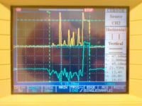
So... I made changes added Shottkys and zeners. I did some test shot on 150V and its realy weird... look at photo of voltage on IGBT gates. And for more my TTL logic stoped working after that shot.
Skynet, Wed Feb 05 2014, 09:04PM
So... I made changes added Shottkys and zeners. I did some test shot on 150V and its realy weird... look at photo of voltage on IGBT gates. And for more my TTL logic stoped working after that shot.

Re: My school coilgun poject
Yandersen, Wed Feb 05 2014, 09:55PM
How are you able to measure both gates at the same time?! Both drivers have different reference level ("ground")! Did you SCed COM and Vs? Obviously everything will burn then. [facepalm]
Yandersen, Wed Feb 05 2014, 09:55PM
How are you able to measure both gates at the same time?! Both drivers have different reference level ("ground")! Did you SCed COM and Vs? Obviously everything will burn then. [facepalm]
Re: My school coilgun poject
Skynet, Wed Feb 05 2014, 10:11PM
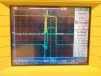
Ok I´m an idiot :D When I want to measure it I did not realized that the ground on the oscilloscope are connected together :D I´ll fix damage tomorow.
I measured voltage on resistors R6 and R7 IC, IGBTs are fine just logic have problem I made multiple shots on diferent voltages on capacitor and everything worked good.
Heres the picture of voltage on gates with 50V on cap(taken before 150V test). With 30V it worked perfectly.

Re: My school coilgun poject
Skynet, Thu Feb 06 2014, 01:42PM
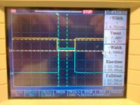
Ok I completely remaked logic circuit (I´ll post it later it still needs some fixes and I dont know how to fix them) but now it works great
At pic is gate voltage and volatge on SD pin on IC.
Video from 200V test (I had to fill a box with cardboard because projectiles were flying through. :D)
Skynet, Thu Feb 06 2014, 01:42PM
Ok I completely remaked logic circuit (I´ll post it later it still needs some fixes and I dont know how to fix them) but now it works great

At pic is gate voltage and volatge on SD pin on IC.
Video from 200V test (I had to fill a box with cardboard because projectiles were flying through. :D)

Re: My school coilgun poject
Yandersen, Thu Feb 06 2014, 09:21PM
Oh, very good. Congrats! :) Will you test 400V now?
Yandersen, Thu Feb 06 2014, 09:21PM
Oh, very good. Congrats! :) Will you test 400V now?
Re: My school coilgun poject
Skynet, Thu Feb 06 2014, 10:08PM
Next week probably I need to short wires between IGBT and main cap also add small HV caps refered by Dantist. Cause I dont want do burn another IGBT its not cheap toy :D
Now I updating scheme to 1.3 revision with 555 timer "logic" its realy messy scheme but work good for 1.st stage at another stages it would be slow. So it would need big improve..hope that we dound some solution.. Issues with the old logic were caused by EMI from coil switching- I used CMOS logic =>bad idea for coilgun :D
After that I try 400V I hope for success

Re: My school coilgun poject
Yandersen, Fri Feb 07 2014, 01:32AM
Skynet, what about current limiting? If you equally drive both IGBT, having them ON while the optogate is dimmed, then the longer that gate is dimmed the longer the coil is ON. So first stages are overpowered and subsequent stages will have less energy stored in coil. Senseless, don't you think? Each coil must have the same energy. Think about different approach: once the gate got dimmed, both IGBTs get opened. But high side IGBT automatically closes after t microseconds and stays off no matter what. This way you get predetermined current and amount of energy stored in coil (whatever built up for t us). When the high side IGBT closes, the current loops in coil and low side IGBT. When the optogate get lighted again, the low side IGBT closes also and coil empties whatever magnetic energy left in it back into the cap. Just use a 555 timer in monovibrator mode to drive high side: trigger it with the short pulse when gate is dimmed and let it switch itself off once the specified time interval ends.
Re: My school coilgun poject
Skynet, Tue Apr 07 2015, 09:50PM
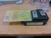
Soooo after realy long pause I´am back!
After previous problems I decided to gain more experience for driving IGBT with best method.
I decided to construct an electrically isolated IGBT driver. Today I finaly assembled new driver and everthing seems to work fine.
Be tuned for more progress


Re: My school coilgun poject
DerAlbi, Wed Apr 08 2015, 07:33AM
Great progress! I like the setup.
If you ever redesign the circuit i would suggest you include a 555-Timer as monoflop and AND-gate the input signal to the IGBT-driver. In this way you cant accidently turn the IGBT on for a longer time than safe given a certain Motor-Inductance. Ive done the same thing (..well at least similar) and its totally safe to operate- It surived every failure condition so far.
When i look into your ICs datasheet, i see you chose the configuration for parallel IGBT-Drive. (presumably for higher drive strength) I can tell from my experience that this causes more problems than it helps to avoid. A slow gate drive is not so bad as you think it is.
Youve got some strayinductance in your half-bridge circuit (specially from the Collector to the Diode above + the ESL of your capacitors and wiring.)
This strayinductance takes time to discharge and thats actually your limiting factor for your switching speed. There is no difference to slower switching and shorter active clamping and fast switching and longer active clamping. The only thing that differs is the complexity of your circuit and how much EMI problems you cause for the sourrounding circuit.
Keep it up! Its really good to see someone here whos actually producing something that works!
Re: My school coilgun poject
Skynet, Wed May 27 2015, 08:30PM
So....
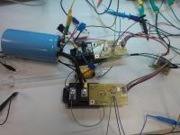
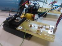
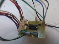
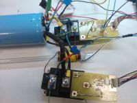
Today I finaly tested halfbridge prototype and it works quite well. But I can only runs at 200V because my drivers have saturation protection set to 300A.
Next step would be adding current trasducer for current regulation that could be achieved with halfbridge ^^
Here is vid from testing:


Re: My school coilgun poject
Skynet, Wed Mar 07 2018, 05:30PM
Well after long frustration i've decided to take this project back on road :D I have managed to redesign gate drivers and completely redesign power stage. It would be multistage too (hopefully 3-5 stages).
There are some prohos of progress and more to come!

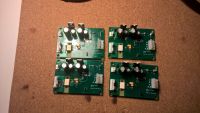
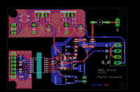
Skynet, Wed Mar 07 2018, 05:30PM
Well after long frustration i've decided to take this project back on road :D I have managed to redesign gate drivers and completely redesign power stage. It would be multistage too (hopefully 3-5 stages).
There are some prohos of progress and more to come!


Re: My school coilgun poject
DerAlbi, Wed Mar 07 2018, 11:57PM
Thats some development! The PCBs look good - its nice to see that someone puts some effort into it
But i dont understand how the driver works.. can you share the schematic and IGBT model number?
DerAlbi, Wed Mar 07 2018, 11:57PM
Thats some development! The PCBs look good - its nice to see that someone puts some effort into it

But i dont understand how the driver works.. can you share the schematic and IGBT model number?
Re: My school coilgun poject
Skynet, Fri Mar 09 2018, 07:04PM
Yup for sure ;) Its just optocoupled GATE driver with saturation protection ACPL337J :) And IGBT module is CM400DU-12F but I use only one IGBT from each module.

Skynet, Fri Mar 09 2018, 07:04PM
Yup for sure ;) Its just optocoupled GATE driver with saturation protection ACPL337J :) And IGBT module is CM400DU-12F but I use only one IGBT from each module.

Re: My school coilgun poject
DerAlbi, Fri Mar 09 2018, 10:16PM
Thanks!
Just some feedback: (your circuit is fine, no worries)
1) I had the idea of desaturation detection myself in an earlier revision of a driver. The issue is that its just expensive, complex and i am not sure that it actually will protect anything. See, in a purely inductive load the current is anyway limited due to ESR most likely below any current your IGBT will desaturate at. This kind of protection is only good to avoid a dead short circuit and to actually help under those conditions (all the inductive peaks and what not) it must be designed really well. Not only the driver but also the overall build.
2) Your driver can deliver 4A without the external transistors - this should be enough. You do not need and (should not have) excessive fast switching.
3) Your IGBTs are way too big ^_^ If they ever die, think about replacing them with smaller TO247 IGBTs. I have some IXGK320N60A3 laying around.. if you want some... they have basically the same ratings, but of course cant dissipate that much heat, which is not necessary anyway.
As far as i can see your setup is built as a asym. halfbridge.. Very good!
How do you want to expand the setup for more coils?
Would you need more IGBTs or whats the plan?
DerAlbi, Fri Mar 09 2018, 10:16PM
Thanks!
Just some feedback: (your circuit is fine, no worries)
1) I had the idea of desaturation detection myself in an earlier revision of a driver. The issue is that its just expensive, complex and i am not sure that it actually will protect anything. See, in a purely inductive load the current is anyway limited due to ESR most likely below any current your IGBT will desaturate at. This kind of protection is only good to avoid a dead short circuit and to actually help under those conditions (all the inductive peaks and what not) it must be designed really well. Not only the driver but also the overall build.
2) Your driver can deliver 4A without the external transistors - this should be enough. You do not need and (should not have) excessive fast switching.
3) Your IGBTs are way too big ^_^ If they ever die, think about replacing them with smaller TO247 IGBTs. I have some IXGK320N60A3 laying around.. if you want some... they have basically the same ratings, but of course cant dissipate that much heat, which is not necessary anyway.

As far as i can see your setup is built as a asym. halfbridge.. Very good!
How do you want to expand the setup for more coils?
Would you need more IGBTs or whats the plan?

Re: My school coilgun poject
Skynet, Sun Mar 11 2018, 08:45PM
Hi,
about desat protection it's meant to be just a failsafe (you never know what could go wrong :D) External transistors are there because i want kinda fast switching just to have something to sort for my final thesis :D Primary for current protection would be used currnet sensor HAS 200-S from LEM. Exesive voltage spikes would be handled with snubber caps across IGBT's ;)
And yes i know that they are quite bigger than its needed but I am not trying to create small coilgun. Also it's easier to maintain wiring. I maybyle consider your's IGBT's for last 2 stages.
And expanding.... Yes I would use more IGBT's and more caps it would be quite a beast :D The settup that you see on picture would be just multiplied.
Re: My school coilgun poject
DerAlbi, Mon Mar 12 2018, 05:53PM
A lot of Questions incoming
So does it shoot already?
May i ask which dimensions your coil and projectile have?
Have you measured the velocity of your projectile?
From what i can see your projectile is around 8-10mm and maybe 40-50mm long?
Your coil length seems equal to the projectile length and the wire is around 2mm i guess. Have you measured the ESR and Inductance of such coils; i would also be interested in the weight of your coils?
Your capacitors are... 350V or 450V with which capacitance?
You use a microcontroller to time things and to evaluate the the light traps. May i ask which kind of current waveform you go for? Is it like PWM, or is it just plain turn on + hold + turn off?
What i find strange is that yi cant figure out which wire goes to what coil - it seems like 2 wires are connected to the IGBTs, but both wires come from different coils - is there anything special going on? (it seems like if you connect the 2 wires in the air, both coils would be in series -- was that your test setup?)
Sorry i ask a lot, but i really like it when some one else builds stuff that is this complex (more than the SCR design). I try to compare it to my acceleration path, maybe we can learn a thing or two from comparing 2 different implementations that seem to have sort of equal dimensions..
DerAlbi, Mon Mar 12 2018, 05:53PM
A lot of Questions incoming

So does it shoot already?

May i ask which dimensions your coil and projectile have?
Have you measured the velocity of your projectile?
From what i can see your projectile is around 8-10mm and maybe 40-50mm long?
Your coil length seems equal to the projectile length and the wire is around 2mm i guess. Have you measured the ESR and Inductance of such coils; i would also be interested in the weight of your coils?
Your capacitors are... 350V or 450V with which capacitance?
You use a microcontroller to time things and to evaluate the the light traps. May i ask which kind of current waveform you go for? Is it like PWM, or is it just plain turn on + hold + turn off?
What i find strange is that yi cant figure out which wire goes to what coil - it seems like 2 wires are connected to the IGBTs, but both wires come from different coils - is there anything special going on? (it seems like if you connect the 2 wires in the air, both coils would be in series -- was that your test setup?)
Sorry i ask a lot, but i really like it when some one else builds stuff that is this complex (more than the SCR design). I try to compare it to my acceleration path, maybe we can learn a thing or two from comparing 2 different implementations that seem to have sort of equal dimensions..
Re: My school coilgun poject
Skynet, Mon Mar 12 2018, 10:31PM
Yup it does shoot but I did tests only on low voltage because I am waiting for snubber caps and I dont want to blow up my IGBT's by doing tests without propper protections.
Projectile and coils are 50mm long and diameter is 10mm for projectile and inner diameter for coil is 11mm.
And yes wire is 2mm in diameter :D ESR for both caps in paralel is 7mΩ for coil i dont have propper equipment for measuring that low resistance. I thing that weight of coils would be affecetd with used epoxy but for now i dont have scale but when i got some i will weight them :D
Caps are 450V and 4700uF.
My current waveform shoud be on + hold + turn off. But for protection i have there current sensors for possible pwm just to reduce current that could blow my IGBT's.
And at last the second coil is not connected at all. Its just prepared to be wired up with another IGBT's :D
Nevermind you could ask everything you want. Maybye some day internet learn how to build coilgun corretly from us :D
Re: My school coilgun poject
DerAlbi, Tue Mar 13 2018, 06:13AM
Thanks for the response Unfortunately there is too much bad information out there (mainly on youtube) so we wont change the world
Considering your snubbers:
the coil it self will oscillate when the current gets back to zero. To prevent this reaching the IGBTs, you can simply put some diodes in series. (Some beefy/cheap P600G from ebay will do, parallel them if you like. A snubber across the coil will help a lot.
If you want to protect the IGBTs from a C-E-voltage spike however, a snubber capacitor wont so the job. There are several reasons:
A true snubber does have a series resistance. Since a snubber is directly stressed with the turn-off current in a halfbridge, the ESR must be low enough to not reach the 600V limit during turn-off. Such a low ESR will however result in an extremely high turn on current. So nothing gained in the end. A RC-snubber does not work in a coilgun, not even a RCD-snubber because the diode is the bottleneck..
The problem is (i learned this "recently"), that the voltage spike on the collector is not caused by ESL, but much much more by the diode forward recovery behavior. (A diode does not become forward conductive immediately). The only way to combat this is to use active clamping:
In your case, use a much larger gate resistor (you really dont need to switch faster than your diodes can handle the resulting turn on, i use 47R as gate resistor, thats still low enough to make the IGBTs faster than my diodes) and put a TVS diode (2 in series to get 450V < V_breakdown < 600V) between collector and gate. This will conduct any excessive C-E-spice towards the gate so during turn of a gate voltage plateau forms that will keep the IGBT conductive until the half-bridge diodes are ready to take over the current from the IGBTs.
So you arent fighting parasitics like ESL but you are most likely fighting semiconductor effects in the diodes. If you think about using faster diodes - forget it. The only way around the diode forward recovery would be using schottky, but they have poor (over-)current rating, so you are bound to silicon junctions.
You really should measure this at low voltages before you try to optimize this with snubbers or what not. You have an oscilloscope! Use it
DerAlbi, Tue Mar 13 2018, 06:13AM
Thanks for the response
 Unfortunately there is too much bad information out there (mainly on youtube) so we wont change the world
Considering your snubbers:
the coil it self will oscillate when the current gets back to zero. To prevent this reaching the IGBTs, you can simply put some diodes in series. (Some beefy/cheap P600G from ebay will do, parallel them if you like. A snubber across the coil will help a lot.
If you want to protect the IGBTs from a C-E-voltage spike however, a snubber capacitor wont so the job. There are several reasons:
A true snubber does have a series resistance. Since a snubber is directly stressed with the turn-off current in a halfbridge, the ESR must be low enough to not reach the 600V limit during turn-off. Such a low ESR will however result in an extremely high turn on current. So nothing gained in the end. A RC-snubber does not work in a coilgun, not even a RCD-snubber because the diode is the bottleneck..
The problem is (i learned this "recently"), that the voltage spike on the collector is not caused by ESL, but much much more by the diode forward recovery behavior. (A diode does not become forward conductive immediately). The only way to combat this is to use active clamping:
In your case, use a much larger gate resistor (you really dont need to switch faster than your diodes can handle the resulting turn on, i use 47R as gate resistor, thats still low enough to make the IGBTs faster than my diodes) and put a TVS diode (2 in series to get 450V < V_breakdown < 600V) between collector and gate. This will conduct any excessive C-E-spice towards the gate so during turn of a gate voltage plateau forms that will keep the IGBT conductive until the half-bridge diodes are ready to take over the current from the IGBTs.
So you arent fighting parasitics like ESL but you are most likely fighting semiconductor effects in the diodes. If you think about using faster diodes - forget it. The only way around the diode forward recovery would be using schottky, but they have poor (over-)current rating, so you are bound to silicon junctions.
You really should measure this at low voltages before you try to optimize this with snubbers or what not. You have an oscilloscope! Use it

Re: My school coilgun poject
hen918, Tue Mar 13 2018, 10:25AM
hen918, Tue Mar 13 2018, 10:25AM
DerAlbi wrote ...
Thanks for the response Unfortunately there is too much bad information out there (mainly on youtube) so we wont change the world
Considering your snubbers:
...
The problem is (i learned this "recently"), that the voltage spike on the collector is not caused by ESL, but much much more by the diode forward recovery behavior. (A diode does not become forward conductive immediately)...
I know this is a rather expensive solution, but have you tried one of the new SiC high voltage schottky diodes?Thanks for the response
 Unfortunately there is too much bad information out there (mainly on youtube) so we wont change the world
Considering your snubbers:
...
The problem is (i learned this "recently"), that the voltage spike on the collector is not caused by ESL, but much much more by the diode forward recovery behavior. (A diode does not become forward conductive immediately)...
Re: My school coilgun poject
DerAlbi, Tue Mar 13 2018, 04:18PM
 Another issue is then, that you still have to fight ESL parasitics if you suddenly can switch this fast.. with SIC you spend a lot of money to switch faster in order to reach the next practical boundary which then needs active clamping again. Nothing (relevant) gained, just money lost.
There is really no need to switch insanely fast in a coilgun anyway.. Switching losses matter in periodic waveforms and are part of thermal design considerations which arent applicable in a coilgun. It has such a negligible duty cycle and switching amount that every thought about optimization is unnecessary. As long as one needs active clamping one switches fast enough
DerAlbi, Tue Mar 13 2018, 04:18PM
female chicken  wrote ...
I know this is a rather expensive solution, but have you tried one of the new SiC high voltage schottky diodes?
I mean i know it exists, but "tried" no. As you said, its expensive and the price difference between one SIC-diode vs PN-Junction diode with the same ratings covers more than the BOM-cost for an active clamp. Not to mention that you need two diodes per halfbridge  wrote ...
I know this is a rather expensive solution, but have you tried one of the new SiC high voltage schottky diodes?
 Another issue is then, that you still have to fight ESL parasitics if you suddenly can switch this fast.. with SIC you spend a lot of money to switch faster in order to reach the next practical boundary which then needs active clamping again. Nothing (relevant) gained, just money lost.
There is really no need to switch insanely fast in a coilgun anyway.. Switching losses matter in periodic waveforms and are part of thermal design considerations which arent applicable in a coilgun. It has such a negligible duty cycle and switching amount that every thought about optimization is unnecessary. As long as one needs active clamping one switches fast enough

Re: My school coilgun poject
Skynet, Tue Mar 13 2018, 09:45PM
Well I am pretty sure that 1uF non inductive snubber cap across IGBT is completely enough because substrate diodes inside my IGBT modules are rated for trr 200ns and thats pretty fast. Actual IGBT's are twice much slower than substrate diodes even with 3.1Ω gate resistor. You must consider that these modules are rated for switching inductive loads in power inverters at high frequency and what I am trying to do with coilgun is pretty much normal operation for them. We use this setup at my university for even more powerfull aplications (electric car chargers, teslacoils, driver for train motor and etc.) without any problem ;)
Skynet, Tue Mar 13 2018, 09:45PM
DerAlbi wrote ...
Thanks for the response Unfortunately there is too much bad information out there (mainly on youtube) so we wont change the world
Considering your snubbers:
the coil it self will oscillate when the current gets back to zero. To prevent this reaching the IGBTs, you can simply put some diodes in series. (Some beefy/cheap P600G from ebay will do, parallel them if you like. A snubber across the coil will help a lot.
If you want to protect the IGBTs from a C-E-voltage spike however, a snubber capacitor wont so the job. There are several reasons:
A true snubber does have a series resistance. Since a snubber is directly stressed with the turn-off current in a halfbridge, the ESR must be low enough to not reach the 600V limit during turn-off. Such a low ESR will however result in an extremely high turn on current. So nothing gained in the end. A RC-snubber does not work in a coilgun, not even a RCD-snubber because the diode is the bottleneck..
The problem is (i learned this "recently"), that the voltage spike on the collector is not caused by ESL, but much much more by the diode forward recovery behavior. (A diode does not become forward conductive immediately). The only way to combat this is to use active clamping:
In your case, use a much larger gate resistor (you really dont need to switch faster than your diodes can handle the resulting turn on, i use 47R as gate resistor, thats still low enough to make the IGBTs faster than my diodes) and put a TVS diode (2 in series to get 450V < V_breakdown < 600V) between collector and gate. This will conduct any excessive C-E-spice towards the gate so during turn of a gate voltage plateau forms that will keep the IGBT conductive until the half-bridge diodes are ready to take over the current from the IGBTs.
So you arent fighting parasitics like ESL but you are most likely fighting semiconductor effects in the diodes. If you think about using faster diodes - forget it. The only way around the diode forward recovery would be using schottky, but they have poor (over-)current rating, so you are bound to silicon junctions.
You really should measure this at low voltages before you try to optimize this with snubbers or what not. You have an oscilloscope! Use it
Thanks for the response
 Unfortunately there is too much bad information out there (mainly on youtube) so we wont change the world
Considering your snubbers:
the coil it self will oscillate when the current gets back to zero. To prevent this reaching the IGBTs, you can simply put some diodes in series. (Some beefy/cheap P600G from ebay will do, parallel them if you like. A snubber across the coil will help a lot.
If you want to protect the IGBTs from a C-E-voltage spike however, a snubber capacitor wont so the job. There are several reasons:
A true snubber does have a series resistance. Since a snubber is directly stressed with the turn-off current in a halfbridge, the ESR must be low enough to not reach the 600V limit during turn-off. Such a low ESR will however result in an extremely high turn on current. So nothing gained in the end. A RC-snubber does not work in a coilgun, not even a RCD-snubber because the diode is the bottleneck..
The problem is (i learned this "recently"), that the voltage spike on the collector is not caused by ESL, but much much more by the diode forward recovery behavior. (A diode does not become forward conductive immediately). The only way to combat this is to use active clamping:
In your case, use a much larger gate resistor (you really dont need to switch faster than your diodes can handle the resulting turn on, i use 47R as gate resistor, thats still low enough to make the IGBTs faster than my diodes) and put a TVS diode (2 in series to get 450V < V_breakdown < 600V) between collector and gate. This will conduct any excessive C-E-spice towards the gate so during turn of a gate voltage plateau forms that will keep the IGBT conductive until the half-bridge diodes are ready to take over the current from the IGBTs.
So you arent fighting parasitics like ESL but you are most likely fighting semiconductor effects in the diodes. If you think about using faster diodes - forget it. The only way around the diode forward recovery would be using schottky, but they have poor (over-)current rating, so you are bound to silicon junctions.
You really should measure this at low voltages before you try to optimize this with snubbers or what not. You have an oscilloscope! Use it

Well I am pretty sure that 1uF non inductive snubber cap across IGBT is completely enough because substrate diodes inside my IGBT modules are rated for trr 200ns and thats pretty fast. Actual IGBT's are twice much slower than substrate diodes even with 3.1Ω gate resistor. You must consider that these modules are rated for switching inductive loads in power inverters at high frequency and what I am trying to do with coilgun is pretty much normal operation for them. We use this setup at my university for even more powerfull aplications (electric car chargers, teslacoils, driver for train motor and etc.) without any problem ;)
Re: My school coilgun poject
DerAlbi, Wed Mar 14 2018, 12:14AM
Dear Skynet
trr (reverse recovery) is something completely different - it characterizes the diode when going from forward to reverse bias. I am speaking of forward recovery. That means going from reverse bias to forward biasing.
The reverse recovery time is meaningless in a coilgun, because the current reaches zero smoothly (no step involved). However the turn on for the diode is hard, because you go from 0A to xxxA in no time. I have diodes that have a 30ns trr rating but they need well over 100ns to take steeply applied current while they allow a forward voltage of several 100V for that time! (instead of the usual 0.6V you would expect). During this time you need active clamping.
You have to realize, that if you put a low ESL/ESR cap across C-E on turn on of the IGBT, you short circuit the capacitor during turn on with/by the IGBT. This will result in a dramatic current spike in the IGBT which results in at least 50mJ turn on loss at 450V. This might be more than any turn off loss that you try to minimize.
Use active clamping. There is no way around it. You have the benefit of using only 450V and having a 600V IGBT.. use bidirectional TVS diodes and you are fine. If you are unsure about it, i had a post here that contained this image:
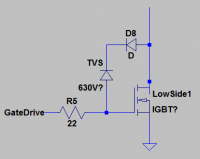
Use only the TVS (put 2x 250V in series) and dont use D8. Use depicted 22R gate resistance.
Part numbers would be 1.5KE250CA. I looked them up, they are easily available on Ebay.
Active clamping is the only counter measure to a voltage spike that ensures minimum switching time and minimum possible switching loss while perfectly protecting the IGBT. Brute forcing a capacitor somewhere where you see a voltage spike issnt the right answer every time.
But you can try... its your IGBTs, of course
Edit:
I just captured a turn off (35A) on my halfbridge for you. The capacitors are charged to 403V at this point.
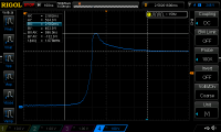
As you can see the turn off takes around 600ns until its all finished. The overshoot is about 130V. This overshoot is purely due to forward recovery of the diode which struggles to take over the current immediately. For my circuit the active clamping does not kick in because its set to around 630V.
It is possible that your setup may behave equalish you mine and you wouldnt need clamping because you have 150V headroom to the 600V igbt limit. But i guess you will turn off much harder current than 35A.. the forward recovery voltage will be much higher in such cases. When i get 130V @ 35A think about how your diodes will struggle at 200A or whatever.
DerAlbi, Wed Mar 14 2018, 12:14AM
Dear Skynet
trr (reverse recovery) is something completely different - it characterizes the diode when going from forward to reverse bias. I am speaking of forward recovery. That means going from reverse bias to forward biasing.
The reverse recovery time is meaningless in a coilgun, because the current reaches zero smoothly (no step involved). However the turn on for the diode is hard, because you go from 0A to xxxA in no time. I have diodes that have a 30ns trr rating but they need well over 100ns to take steeply applied current while they allow a forward voltage of several 100V for that time! (instead of the usual 0.6V you would expect). During this time you need active clamping.
You have to realize, that if you put a low ESL/ESR cap across C-E on turn on of the IGBT, you short circuit the capacitor during turn on with/by the IGBT. This will result in a dramatic current spike in the IGBT which results in at least 50mJ turn on loss at 450V. This might be more than any turn off loss that you try to minimize.
Use active clamping. There is no way around it. You have the benefit of using only 450V and having a 600V IGBT.. use bidirectional TVS diodes and you are fine. If you are unsure about it, i had a post here that contained this image:

Use only the TVS (put 2x 250V in series) and dont use D8. Use depicted 22R gate resistance.
Part numbers would be 1.5KE250CA. I looked them up, they are easily available on Ebay.
Active clamping is the only counter measure to a voltage spike that ensures minimum switching time and minimum possible switching loss while perfectly protecting the IGBT. Brute forcing a capacitor somewhere where you see a voltage spike issnt the right answer every time.
But you can try... its your IGBTs, of course

Edit:
I just captured a turn off (35A) on my halfbridge for you. The capacitors are charged to 403V at this point.

As you can see the turn off takes around 600ns until its all finished. The overshoot is about 130V. This overshoot is purely due to forward recovery of the diode which struggles to take over the current immediately. For my circuit the active clamping does not kick in because its set to around 630V.
It is possible that your setup may behave equalish you mine and you wouldnt need clamping because you have 150V headroom to the 600V igbt limit. But i guess you will turn off much harder current than 35A.. the forward recovery voltage will be much higher in such cases. When i get 130V @ 35A think about how your diodes will struggle at 200A or whatever.
Re: My school coilgun poject
Skynet, Thu Mar 15 2018, 07:30PM
Hi Albi,
in theory it sounds quite perfect :D But as I know using of active clamping is more risky for my transistors than putting caps across them. When active clamping engages there is possibility that transistor would go to linear mode (just few volts on gate) and you don’t want to have current flowing though IGBT's when its hundreds volts across them. That would kill them for sure ;)
The correct solution is precise geometric placement of components to reduce stray inductance’s and using snubber caps. That’s the way how it should be done. Inside IGBT module you have this sorted by manufacter so nothing to worry about. If it were true what you say no motor regen would be possible... What we have there hmm... current going from zero to hundred amps and it works like a charm without any active clamping. Interesting isn't it?
If you use discrete components its even more crucial to minimize every possible cm of wire that you don’t need. Also you have to count with some voltage spikes in design. So my actual voltage wouldn’t go over 350V on these IGBT's. Its rule number one that you use components rated for at least twice much voltage that is used in circuit. So if i ever wanna go for full power it wouldn’t be on these boys ;)
Re: My school coilgun poject
DerAlbi, Fri Mar 16 2018, 03:59AM
Ah i i know now where your thought process comes from! Thanks.
-> Your "correct solution" is unfortunately flawed.
First of all, a physical well done build will not reduce semiconductor effects. As i said, actual ESL might be way less significant than the forward recovery (which mimics inductive behavior of a diode voltage wise, but resistive behavior power loss wise). There for you can shuffle and optimize your components for ever never becoming better than your components allow it. So you are currently overthinking parasitics when the problem might actually be somewhere else.
-> Also your "linear operation" argument is flawed.
Think about it.. a capacitor can only store energy in order to not let it heat up the IGBTs. At 450V a 1uF capacitor hosts 101mJ of energy. (at 600V its 180mJ). So your snubber only helps as long all the energy in your assumed stray inductance is less than this. And yes, during turn off then the IGBT is protected from this stray energy as long as the capacitor eats it all.
But where does the energy go? You can dissipate it it away in a parallel resistor but that takes time and introduces a static current. As soon as you turn on the IGBT again, the 101mJ are simply dissipated at turn on, because the capacitor is short circuited then. And the heat is generated inside the IGBT.
So overall you dont solve the problem you mention, you simply shift it from turn-off to turn-on. Nothing gained here.
-> Then again think again about what amount of energy you are talking about!
Your capacitor can only handle 180mJ switching loss anyway, this is something your IGBT silicon can handle too and even more - this is why active clamping wins in every position:
it dissipates the stray energy during switching, which also happens in your solution too (just not at turn-off, but at turn-on). Additionally active clamping works even in a very bad build, while your capacitor solution is restricted to 180mJ stray energy capability..
-> Btw, 180mJ heat dissipation is equivalent to 112.5A for 1ms (@1.6V VCEsat) on your IGBT (roughly 250A peak current on a 1ms saw sooth current wave form).
Given your setup, i guess you will exceed this anyway (either current wise or time duration wise, likely both).
So if you think that this energy can destroy/harm your IGBT, you have a way bigger problem.
-> Now lets continue:
180mJ allows for 9uH stray inductance @ 200A or 2.25µH @ 400A. You can see that this is excessive!! You will never have stray inductances that big.
So lets think about about the turn on, where your CE-Capacitor is short circuited under normal conditions: you will inevitably dissipate 101mJ there (=1uF @ 450V). Even 101mJ is equivalent to a 1.26µH stray inductance @ 400A. You will never ever have this! The same argument holds true for 350V...
Therefor your capacitor solution will increase your switching loss, instead of minimizing it.
Even worse: the turn-on peak current due to the schort circuit can even latch up your IGBT, turning on its parasitic SCR, and you are just exploding your IGBT right there.
I can repeat my self, active clamping is the way to go, there is no more optimal solution.
I push my 650V IGBTs to 630V clamping voltage. No fatalities yet
So in conclusion you are adding a capacitor in order to *increase* your switching losses, *risking an SCR latchup*, while *not gaining confidence* in your build that you will adhere to your voltage specifications while making the build *even bigger* with *heavier* components, all in order to avoid using 2 diodes that would solve all your issues. Every point you wanted to make better in your build you actually worsened; and its easily shown with just energy conservation arguments, no special math or simulations involved.
DONT.
However if you can show calculations that show why you choose a 1µF capacitor, i would love to hear an explanation
Just another remark: i will stop bothering you changing your topology. I made my point, you made yours. I can destroy your position in every respect, but its about you to choose to listen. The whole argument is about some mJ energy amount that is suboptimal. Going for your 1µF @ 350V will likely work, if the IGBT does not latch up which is a serious risk. I just want to help you here, and as i said, there is a lot of bad information out there specially regarding coil guns. Your misconceptions about your betterment of your circuit would make another example where something was simply not thought through. Yet it will be a (hopefully) working solution, but "working" means only "sufficient", not "good". Yet the "working" will make you feel that it is "good" leaving you with a fundamentally flawed, false experience with gained confidence in decision what can be objectively proven wrong. I just dont want you to be another person who, in the end, didnt actually know what he was doing while feeling confident that he is on the right track.
DerAlbi, Fri Mar 16 2018, 03:59AM
Ah i i know now where your thought process comes from! Thanks.
-> Your "correct solution" is unfortunately flawed.
First of all, a physical well done build will not reduce semiconductor effects. As i said, actual ESL might be way less significant than the forward recovery (which mimics inductive behavior of a diode voltage wise, but resistive behavior power loss wise). There for you can shuffle and optimize your components for ever never becoming better than your components allow it. So you are currently overthinking parasitics when the problem might actually be somewhere else.
-> Also your "linear operation" argument is flawed.
Think about it.. a capacitor can only store energy in order to not let it heat up the IGBTs. At 450V a 1uF capacitor hosts 101mJ of energy. (at 600V its 180mJ). So your snubber only helps as long all the energy in your assumed stray inductance is less than this. And yes, during turn off then the IGBT is protected from this stray energy as long as the capacitor eats it all.
But where does the energy go? You can dissipate it it away in a parallel resistor but that takes time and introduces a static current. As soon as you turn on the IGBT again, the 101mJ are simply dissipated at turn on, because the capacitor is short circuited then. And the heat is generated inside the IGBT.
So overall you dont solve the problem you mention, you simply shift it from turn-off to turn-on. Nothing gained here.
-> Then again think again about what amount of energy you are talking about!
Your capacitor can only handle 180mJ switching loss anyway, this is something your IGBT silicon can handle too and even more - this is why active clamping wins in every position:
it dissipates the stray energy during switching, which also happens in your solution too (just not at turn-off, but at turn-on). Additionally active clamping works even in a very bad build, while your capacitor solution is restricted to 180mJ stray energy capability..
-> Btw, 180mJ heat dissipation is equivalent to 112.5A for 1ms (@1.6V VCEsat) on your IGBT (roughly 250A peak current on a 1ms saw sooth current wave form).
Given your setup, i guess you will exceed this anyway (either current wise or time duration wise, likely both).
So if you think that this energy can destroy/harm your IGBT, you have a way bigger problem.
-> Now lets continue:
180mJ allows for 9uH stray inductance @ 200A or 2.25µH @ 400A. You can see that this is excessive!! You will never have stray inductances that big.
So lets think about about the turn on, where your CE-Capacitor is short circuited under normal conditions: you will inevitably dissipate 101mJ there (=1uF @ 450V). Even 101mJ is equivalent to a 1.26µH stray inductance @ 400A. You will never ever have this! The same argument holds true for 350V...
Therefor your capacitor solution will increase your switching loss, instead of minimizing it.

Even worse: the turn-on peak current due to the schort circuit can even latch up your IGBT, turning on its parasitic SCR, and you are just exploding your IGBT right there.

I can repeat my self, active clamping is the way to go, there is no more optimal solution.
wrote ...
Also you have to count with some voltage spikes in design. So my actual voltage wouldn’t go over 350V on these IGBT's. Its rule number one that you use components rated for at least twice much voltage that is used in circuit.
Argument wise, you are shooting your self in the foot here. Active clamping will !!ensure!! that your voltage spikes will never reach your IGBTs Vce-rating, no other solution does that for you, as you seem to realize yourself. Your rule number one is fundamentally wrong: its fear driven and not specification/engineering driven. It wastes half of your IGBTs rating for something thats easily avoidable by choosing the right circuit/topology. Your IGBT can handle 600V. Period.Also you have to count with some voltage spikes in design. So my actual voltage wouldn’t go over 350V on these IGBT's. Its rule number one that you use components rated for at least twice much voltage that is used in circuit.
I push my 650V IGBTs to 630V clamping voltage. No fatalities yet

So in conclusion you are adding a capacitor in order to *increase* your switching losses, *risking an SCR latchup*, while *not gaining confidence* in your build that you will adhere to your voltage specifications while making the build *even bigger* with *heavier* components, all in order to avoid using 2 diodes that would solve all your issues.
 Every point you wanted to make better in your build you actually worsened; and its easily shown with just energy conservation arguments, no special math or simulations involved.
DONT.
However if you can show calculations that show why you choose a 1µF capacitor, i would love to hear an explanation

Just another remark: i will stop bothering you changing your topology. I made my point, you made yours. I can destroy your position in every respect, but its about you to choose to listen. The whole argument is about some mJ energy amount that is suboptimal. Going for your 1µF @ 350V will likely work, if the IGBT does not latch up which is a serious risk. I just want to help you here, and as i said, there is a lot of bad information out there specially regarding coil guns. Your misconceptions about your betterment of your circuit would make another example where something was simply not thought through. Yet it will be a (hopefully) working solution, but "working" means only "sufficient", not "good". Yet the "working" will make you feel that it is "good" leaving you with a fundamentally flawed, false experience with gained confidence in decision what can be objectively proven wrong. I just dont want you to be another person who, in the end, didnt actually know what he was doing while feeling confident that he is on the right track.
Re: My school coilgun poject
Skynet, Sat Mar 17 2018, 08:39PM
Oh man... Calm down :D
At first my design is not focused on effiency at all... My coils are hand made garbage, my barrel have thick walls so I don’t have big expectations. Some mJ in switching loses are meaningless for me. And I am trying to build powerful coilgun (I just need to get to specific muzzle velocity at all costs because it would be replacing big air canon at my university) so if it would be big, heavy and complicated it’s okay...
Yes, I know that with snubbers I will dissipate some energy to my transistors but it’s just fraction of what they could survive without any problems.
About my IGBT modules...
Diodes inside these modules are designed to take over maximum current of transistors. => It just way how it works in every frequency converter, motor driver and etc. without using active clamping. Foward recovery exist but it's not as big prolem as you think.
IGBT's in modules are latch up proof (yes manufacturers can make them nowadays) so again => nothing to worry about
About my rule for design of VCE rating...
I don’t force you to use it. And man... It’s not fear at all its just failsafe you never know what could go possibly wrong in your circuit. Some protection could fail and if you have your design at its limit for normal operation what it will do in fail condition? The cost for more VCE room is acceptable for more beefy circuit.
And 1uF snubber is just commonly used value in power circuits for my size of IGBT modules but you can calculate it. Some manufacturers like Infineon released equations how to precisely determine value but it's not worth spent time if 1uF works flawlessly ;)
Re: My school coilgun poject
hen918, Sun Mar 18 2018, 12:51AM
An interesting discussion.
Assuming an modern IGBT (if latchup isn't really a problem anymore, I have never experienced it, but I rarely design circuits with IGBTs), the old fashioned snubber seems the way to go. The switching frequency of most coil-guns is *very* low compared to even a large SMPS, so 0.1 J of energy dissipation seems negligible if you are switching several kJ.
If you require ultimate efficiency, small size, precise current control with PWM, and fast fire rates, maybe active clamping is the way to go.
Remember that Skynet's Coil-gun has very different specification to yours DerAlbi.
BTW, the hen in my name is short for Henry. Why I choose hen918 I don't know. I've used it for most of my life.
Re: My school coilgun poject
DerAlbi, Sun Mar 18 2018, 03:34PM
1) "not recommended for new designs" = old
2) no short circuit specification = no proof of latch up resistance
Stating that "other IGBTs are latch up resistance, then mine is too" is.. well what is it like? Maybe like jumping off a bridge without a rubber band after you saw bungee jumping on TV.
Never EVER assume. When there is high power involved, only facts count. Also if others use some capacitor somewhere, it doesnt mean, its the right solution to you too.
You also assume that forward recovery is not an issue when i went the extra mile to provide hard evidence to the contrary. I know that forward recovery is not a very often discussed topic, yet it is real and in fact maybe an issue.
Hen, I dont think you interpret my concerns the right way.. its really not about efficiency.. because that does not come from the IGBTs in the end.. and i am actually interested in what efficiency will be achieved - if its bad its also an interesting information to me. I realize that his setup is very different to mine, thats whats makes it interesting. But it does not mean, that we have no common problems to solve.
My concern is about doing the right thing regarding the circuit design. This is the design of a coilgun switching stage, not an SMPS. Its really about educating about misconceptions that seem to be prevalent here. Specially when its obvious that not even the most basic calculations were made during reasoning about the topology..
If Skynet says, in a SMPS, IGBTs are used this way [with 1µF], and his conclusion is that its ok to also add an 1µF capacitor, thats a fundamental problem! I am not sure if he understands that maybe the SMPS implements ZVS where the capacitor isnt even a snubber. Are you sure, its not a resonant cap instead? Should i really shut up? Better safe than sorry when it comes to high power switching.
I also would like to ask you why you would prefer a snubber capacitor instead of the much more universal active clamping circuit - specially when its smaller, cheaper, simpler and more reliable than a capacitor... is it because.. its unknown maybe?

DerAlbi, Sun Mar 18 2018, 03:34PM
"Skynet" wrote ...
IGBT's in modules are latch up proof (yes manufacturers can make them nowadays) so again
IGBT's in modules are latch up proof (yes manufacturers can make them nowadays) so again
Henry the chicken^_^ wrote ...
Assuming an modern IGBT
No worries, i see where your ideas come from, but lets see the datasheet: Assuming an modern IGBT
1) "not recommended for new designs" = old
2) no short circuit specification = no proof of latch up resistance
Stating that "other IGBTs are latch up resistance, then mine is too" is.. well what is it like? Maybe like jumping off a bridge without a rubber band after you saw bungee jumping on TV.
Never EVER assume. When there is high power involved, only facts count. Also if others use some capacitor somewhere, it doesnt mean, its the right solution to you too.
You also assume that forward recovery is not an issue when i went the extra mile to provide hard evidence to the contrary. I know that forward recovery is not a very often discussed topic, yet it is real and in fact maybe an issue.
Hen, I dont think you interpret my concerns the right way.. its really not about efficiency.. because that does not come from the IGBTs in the end.. and i am actually interested in what efficiency will be achieved - if its bad its also an interesting information to me. I realize that his setup is very different to mine, thats whats makes it interesting. But it does not mean, that we have no common problems to solve.
My concern is about doing the right thing regarding the circuit design. This is the design of a coilgun switching stage, not an SMPS. Its really about educating about misconceptions that seem to be prevalent here. Specially when its obvious that not even the most basic calculations were made during reasoning about the topology..
If Skynet says, in a SMPS, IGBTs are used this way [with 1µF], and his conclusion is that its ok to also add an 1µF capacitor, thats a fundamental problem! I am not sure if he understands that maybe the SMPS implements ZVS where the capacitor isnt even a snubber. Are you sure, its not a resonant cap instead? Should i really shut up? Better safe than sorry when it comes to high power switching.
I also would like to ask you why you would prefer a snubber capacitor instead of the much more universal active clamping circuit - specially when its smaller, cheaper, simpler and more reliable than a capacitor... is it because.. its unknown maybe?
It’s not fear at all its just failsafe you never know what could go possibly wrong in your circuit..that is fear. If you dont know what will happen, why prepare for the worst... because of.. optimism?

Re: My school coilgun poject
Skynet, Sun Mar 18 2018, 04:04PM
Albi... Before I stared to mess with power electronic I’ve studied microelectronics and as I know my IGBTs are trench gate design which is latch up proof.
And why prepare for the worst? Maybe if some of my protection fails (and yes it could happen to everyone) and I was and dumb that my voltage ratings are at its limits in normal operation? I don’t know what they learn you at your university but we are just used to have comfortable room. It doesn’t give you confidence in your design but chance of catastrophical failure would be less possible ;)
Re: My school coilgun poject
DerAlbi, Sun Mar 18 2018, 06:17PM
I taught in university, that having no confidence in a design is already the catastrophic failure.
Thanks for your IGBT clarification! Short circuit or "snub-circuit?"the hell out of this thing then! It will live, no doubt.
DerAlbi, Sun Mar 18 2018, 06:17PM
I taught in university, that having no confidence in a design is already the catastrophic failure.

Thanks for your IGBT clarification! Short circuit or "snub-circuit?"the hell out of this thing then!
 It will live, no doubt.
Re: My school coilgun poject
Skynet, Sun Mar 18 2018, 11:13PM
Update:
I've just started to wire up the second stage and my LEM current sesors arrived so I am trying to mess with them ;) When it will be done I'll try to do some tests on realy low voltage.
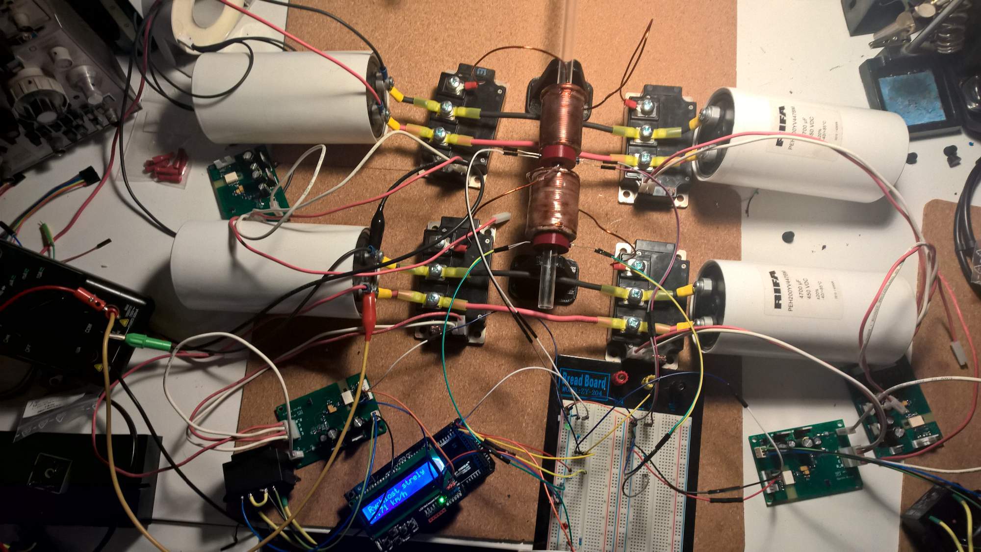
Skynet, Sun Mar 18 2018, 11:13PM
Update:
I've just started to wire up the second stage and my LEM current sesors arrived so I am trying to mess with them ;) When it will be done I'll try to do some tests on realy low voltage.

Re: My school coilgun poject
DerAlbi, Mon Mar 19 2018, 04:24AM
Ohh!! Current sensors! Yes yes yes, i hope you have a digital oscilloscope, so you can share current waveforms. I just made analog isolators with 1MHz bandwidth for up to +/-5V input and 2kV isolation voltage including x1/x10/x100 optional gain.. but they will take some time
The cool thing about your 2 coil setup is that your 2nd coil seems to be movable. (or is it glued in place?)
It would be a great experiment to change the distance between the coils, measure their coupling factor and see how the individual efficiency of the 2nd coil changes. Thats something i cant do with my setup and it really bothers me. To be honest i am currently at a low point with my own build. Not due to disappointment, but due to lack of understanding why it performs much better than expected. Somehow there is some magic energy transport between stages, but i cant figure out what it is or where it comes from. As you can see by my word choice "magic" i cant even define the mechanism at play I hope current measurement sheds some light.
Btw, for consistent measurements, i would suggest you add a 3rd (maybe even a 4th) light trap so you can determine the projectile speed reliably after acceleration has finished..
For now 7.71km/h sounds like its alive ^_^
DerAlbi, Mon Mar 19 2018, 04:24AM
Ohh!! Current sensors! Yes yes yes, i hope you have a digital oscilloscope, so you can share current waveforms. I just made analog isolators with 1MHz bandwidth for up to +/-5V input and 2kV isolation voltage including x1/x10/x100 optional gain.. but they will take some time

The cool thing about your 2 coil setup is that your 2nd coil seems to be movable. (or is it glued in place?)
It would be a great experiment to change the distance between the coils, measure their coupling factor and see how the individual efficiency of the 2nd coil changes. Thats something i cant do with my setup and it really bothers me. To be honest i am currently at a low point with my own build. Not due to disappointment, but due to lack of understanding why it performs much better than expected. Somehow there is some magic energy transport between stages, but i cant figure out what it is or where it comes from. As you can see by my word choice "magic" i cant even define the mechanism at play
 I hope current measurement sheds some light.
Btw, for consistent measurements, i would suggest you add a 3rd (maybe even a 4th) light trap so you can determine the projectile speed reliably after acceleration has finished..
For now 7.71km/h sounds like its alive ^_^
Re: My school coilgun poject
Skynet, Tue Mar 20 2018, 02:37AM
Made some progress again :)
Lot of wiring done but not at the end yet :D Got 2 stages to work at 24V (just testing firing algorithm) without any protection at all. Eff for 1st coil 3.92% and second 11.76% but it's not much precise (need one more optogate just for 1st stage).
Next steps are current sensors and some dumb charger to get more voltage. Also ordered another 4 IGBT modules (Toshiba MG200J2YS50) it's some cheap used crap but it will do the job for now.


Re: My school coilgun poject
DerAlbi, Tue Mar 20 2018, 04:34AM
May i ask how you define your efficiency? There are several ways:
1) Overall shot:
1.1) Ekin / Initial_Ecap
which is equivalent to the SCR design (implies weight- and volume efficiency)
1.2) Ekin / Used_Ecap
which takes into account the advantages of a half bridge design, however it says nothing about if you have a viable build or not
2) Individual Coil
[EKin_Coil(n) - Ekin_Coil(n-1)] / [ Final_ECap(n) - Final_ECap(n-1) ] = "Gained Ekin from coil n" / "Used Ecap from coil n"
which is more a design verification and tells more about if an individual coil is driven correctly
There is merit to all of those definitions, so i ask.
11% at this velocity sounds pretty amazing (no matter which definition)
Re: My school coilgun poject
Skynet, Tue Mar 20 2018, 01:30PM
I calculate efficiency separately for individual coils. So "Gained Ekin from coil n" / "Used Ecap from coil n" but for now I just count that it eats all energy from cap (1-2V on caps after shot is negligible for now) so it's not much accurate :D
Working on voltage feedback from caps to processor that will give me posiibility to count with recuperation.
Re: My school coilgun poject
DerAlbi, Wed Mar 28 2018, 11:39PM
More updates!!
DerAlbi, Wed Mar 28 2018, 11:39PM
More updates!!

Re: My school coilgun poject
Skynet, Fri Mar 30 2018, 01:36PM
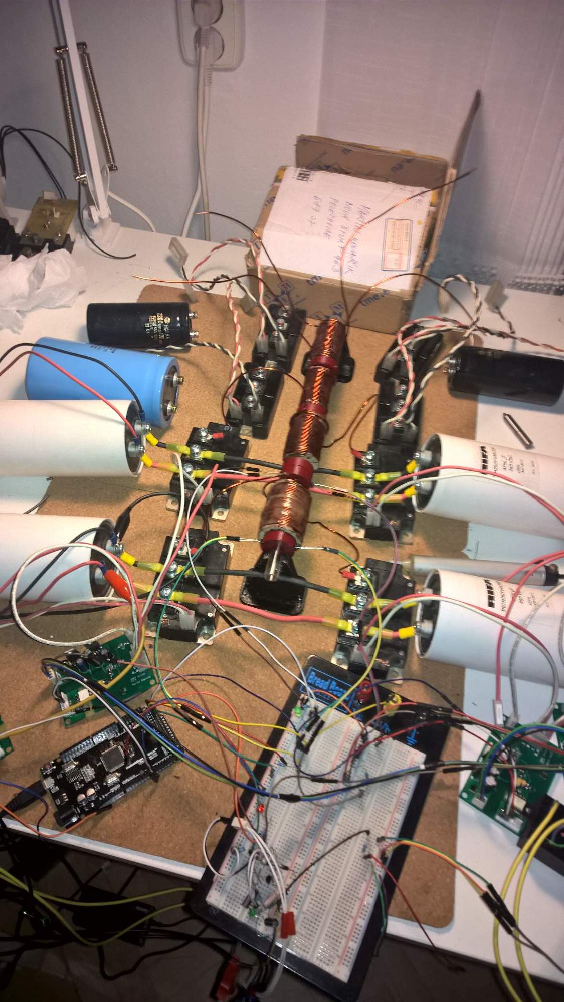
Not much to write about started to wire up more stages, and still playing with current sesnors and algorithm for current regulation. More progress would be done after easter break ;)
Skynet, Fri Mar 30 2018, 01:36PM
Not much to write about started to wire up more stages, and still playing with current sesnors and algorithm for current regulation. More progress would be done after easter break ;)

Re: My school coilgun poject
Skynet, Wed Apr 04 2018, 08:47PM
Just playing with more voltage :D Remaked firing algorithm so now i dont know speeds but hopefully it will be fixed soon to be able to get some results ;)
On this shot end speed shoud be 12,5m/s and final voltage on caps was around 20V.
Skynet, Wed Apr 04 2018, 08:47PM
Just playing with more voltage :D Remaked firing algorithm so now i dont know speeds but hopefully it will be fixed soon to be able to get some results ;)
On this shot end speed shoud be 12,5m/s and final voltage on caps was around 20V.
Re: My school coilgun poject
DerAlbi, Wed Apr 04 2018, 09:41PM
The kickback is a bit scary Fixing your acceleration path to your table might help. (it also consumes energy to move the coils)
Looks like roughly 2.5J.. whats in the box to stop the projectile?
DerAlbi, Wed Apr 04 2018, 09:41PM
The kickback is a bit scary
 Fixing your acceleration path to your table might help. (it also consumes energy to move the coils)
Looks like roughly 2.5J.. whats in the box to stop the projectile?
Re: My school coilgun poject
Skynet, Wed Apr 25 2018, 02:28PM
Time for updateeee :P
So I almost wired up everything for 4 stage test for weekend.
Also did some measuring and for now we are at 30,41m/s with caps charged to 200V ;)
Video from test there:
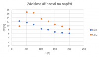
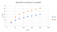
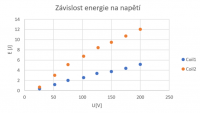
Skynet, Wed Apr 25 2018, 02:28PM
Time for updateeee :P
So I almost wired up everything for 4 stage test for weekend.
Also did some measuring and for now we are at 30,41m/s with caps charged to 200V ;)
Video from test there:


Re: My school coilgun poject
DerAlbi, Wed Apr 25 2018, 06:27PM
Mighty.
Still dont like the kick-back though...
Whats in the box? This is currently one of my bigger pains.. stopping the projectile.. I use some modeling clay mixed with Kevlar fibers on a hard foam board to stop it.. but that leaves the projectile dirty and penetration is more than one projectile length.. so recovery is frustrating.
Unfortunately i cant read your diagram titles.. is the 3rd picture the individual coil contribution to kinetic energy or is it the overall result?
Also your efficiency worries me.. are you just adjusting voltage or are you also optimizing the switching times for every voltage level [according to the projectile speed]?
Re: My school coilgun poject
Skynet, Wed Apr 25 2018, 09:22PM
Kickback is quite problem now I agree but hopefully some glue shoud fix that damn coils to table :D
In the box are multiple layers of thin cardboard and my scarf to dampen it just a little :D
And in 3rd picture is overall result so if you want just coil 2 you need to deduct energy of coil 1.
About voltage I just giving more charge to capacitors. My switching times are strictly based on projetile position to coil. Dropping effiency at more power is quite weird. It could be relied to poor magnetic coupling or something like that but now I dont have much time to make new coils :D
Re: My school coilgun poject
DerAlbi, Thu Apr 26 2018, 04:58AM
Well efficiency in coilguns is a bitch to master :-/
There are a lot of reasons why your efficiency can be messed up.
1) Positional switching is not good enough. It should be more sophisticated. Higher voltage leads to faster current rise times which energized the coil before it can do its most energy transfer.
2) Saturation of course.. based on your geometry and my gut feeling i would expect a coil of yours be efficient up to maybe 5J to 7J energy transfer (however and this is what you are currently doing but already experiencing heavy degradation)
3) Kickback. Moving/Accelerating your heavy coils (4 of them) backwards also consumes energy that is mechanically dumped into your build... that consumes energy that is not in the projectile.. Although the coil movement seems springy the recovery (forward motion) occurs only after the projectile exited, so the energy is truly lost.. i experience the same in my coilgun.. when i shoot from my hand the gun performs measurably worse due to my mushy human body compared to my stand its usually shot from.
Do you have your coil data available? (Turns, Inductance, Resistance?, Switching times of your IGBTs)
Have you made a Spice-Simulation what currents you expect? Just a ballpark figure is enough to help reasoning...
Alternatively you can just watch your cap voltage on an digital oscilloscopic and calculate the current that way...
Or use a shunt.. but that is hard to implement (due to your build)
Re: My school coilgun poject
Skynet, Sun May 20 2018, 05:52PM
Hi,
another update there ;) Ive just managed to fire up all 4 stages :p Still sorting some problems with current sensing to be able use full power. So far best result 41,25 m/s with 22,1 J of energy with coils eff. C1: 6,9% C2: 10,9% C3: 19,4% C4: 45,3%.
Still a lot of work to do but slowly getting to the point that I want hopefully 200m/s would be achievable speed :D
For Albi:
My coils have these parametres:
Coil1: L=663uH, R=240mohm, N= unknown
Coil2: L=385uH, R=170mohm, N= unknown
Coil3: L=267uH, R=129mohm, N= unknown
Coil4: L=242uH, R=110mohm, N= unknown
Switching times are strictly dependend on singnal from front optogate so: dimmed=on free=off. Coil is switched on 2,5mm before projectile reaches coil and 2,5mm before projectile get to center of coil.
I have my simulation and current get to that high value that I need current regulation (easily over 400A) Ive included result ;)

]test.pdf[/file]
Skynet, Sun May 20 2018, 05:52PM
Hi,
another update there ;) Ive just managed to fire up all 4 stages :p Still sorting some problems with current sensing to be able use full power. So far best result 41,25 m/s with 22,1 J of energy with coils eff. C1: 6,9% C2: 10,9% C3: 19,4% C4: 45,3%.
Still a lot of work to do but slowly getting to the point that I want hopefully 200m/s would be achievable speed :D
For Albi:
My coils have these parametres:
Coil1: L=663uH, R=240mohm, N= unknown
Coil2: L=385uH, R=170mohm, N= unknown
Coil3: L=267uH, R=129mohm, N= unknown
Coil4: L=242uH, R=110mohm, N= unknown
Switching times are strictly dependend on singnal from front optogate so: dimmed=on free=off. Coil is switched on 2,5mm before projectile reaches coil and 2,5mm before projectile get to center of coil.
I have my simulation and current get to that high value that I need current regulation (easily over 400A) Ive included result ;)


]test.pdf[/file]
Re: My school coilgun poject
DerAlbi, Mon May 21 2018, 05:05AM
Thanks for sharing your results. It is getting very interesting; I dont see the 200m/s as realistic but anyway you reached the same level of performance as my gun does. (strictly energy wise). Your coils are noticeably better than mine - your L/R time constant is nearly twice as long as my coils which should give you an edge.
Unfortunately i cant really interpret the first photo because i dont know if thats before or after a shot and if its after i dont know the start voltage nor the capacitance. It would also be interesting to have an overall efficiency (Ekin/Ecap_all) for better comparison - if your first coil has only 7%eff but pushes only 10% of the energy into the projectile the 7% dont mean as much if 90% Ekin is pushed by a 40% eff coil, i hope you understand.
Your simulation seems to be lacking detail (circuitry) - it plainly shows that your capacitor voltage goes negative during your on-cycle which is not possible in a half bridge. Anyway, i get the point.
Edit: stupid me. Its the coil voltage i was complaining about, thats ok! I was confused for a second and judged; i apologize - the cap voltage is fine
I doubt your switching is optimal yet. Its a nice start, but it may be beneficial to experiment more - i would suggest to use the timings the current shots have.. just log them through the optogates, then make it a fixed sequence and then vary parameters. I figure there is a lot of headroom for improvements - which would be very interesting because if you reach the efficiency of my design with much smaller technical investment that would mean a lot (mainly that i am an over-engineering, time wasting idiot, lost in his topic of interest, working under false assumptions, suffering wildly the dunning-kruger effect)
I am not sure if you really should go for current sensing for current regulation because every shot is kind of the same as any other shot but not really [due to initial projectile position variation]. A regulation scheme would only introduce more unknowns and would add exit velocity inconsistencies. I would again suggest you use a fixed (maybe still triggered by the optogates?) switching sequences to simply avoid excessive currents by shorter but repeated on times [PWM]. Current sensing is mainly interesting to compare simulation to reality and to study the impact of the projectile to the real current waveform.
Again, those a very interesting results. Specially the 4th coil amazes me. From what you say i wouldnt have thought it possible to have >40% coil-efficiency with the setup and switching scheme you propose. It kind of humbles the achievements in my gun. Stop working on it! I pay you off; oh wait, i spent all my money on a more sophisticated version of the same thing

Re: My school coilgun poject
Skynet, Tue May 22 2018, 08:08PM
Hi,
dont border about first photo its just showing function for cap carger monitor ;) Yup I understand but for now is quite nice progress for me. From measurements that Ive done it seems that effiency is exponencialy depended on entry speed. So for next think to do is changing parameters for 4th coil and try to determine what to do with other coils to get same results ;) Ive included exel file with all data so you can look for anything you want.
About optimizing switching I kinda want to do it eventualy but for now I need to get some faster MCU because Arduino is on its limits for now :DDD
And current regulation shoud be there only just as failsafe for IGBTs in normal operation I want just on-off state.
Wish you luck with your gun man ;)
Edit: Shiet this forum doesnt like exel files... :D So here you go: https://mega.nz/#!l51T0KiZ!4B03ez6BowlADIy2mCXu26DvUViGinGNsWexc-HxTf0
Re: My school coilgun poject
DerAlbi, Wed May 23 2018, 04:54AM
I do actually calculate the current and capacitor voltage waveforms, heatloss of the coil and IGBTs in real time by calculating the differential equations every 10µs. I configure the algorithm by providing the coil properties and security boundaries such as "max 20J heat loss per coil, max current is xxxA".
What i want to say is: you dont need to measure the current to know how high it is in a simple setup such as an Capacitor + Inductor with ESR setup. Remember: any additional hardware is an additional point of failure.
Regarding your Excel sheet, i see now why your 4th coil is so efficient now . You push only 3.5J with it - thats very much on the low side given your geometry. That eases my mind in comparison to my gun *puuh*
On further inspection your coils pushe 7J, then 7.6,J then 4J then 3.5J, so you get diminishing returns the more stages you have. (further making 200m/s impossible)
Your guess that individual coil efficiency depends on entry velocity might not be fully correct then (it is partly) there are a lot more correlations in your excel sheet than this statement. => The less energy you push, the more efficient it will be, thats well known. However for this to be true, the switching time must be optimal of course.
BTW, check your ICQ
DerAlbi, Wed May 23 2018, 04:54AM
And current regulation shoud be there only just as failsafe for IGBTs in normal operation I want just on-off state.I solved this security issue by using 2 microcontrollers. One for the shot (timer-interrupt driven state machine) and one supervisor-controller that actually reads the pins of the shot-control and performs continuous matching to preprogrammed (by communication between the cpus, not hard coded!) sequences. If a fault is detected the IGBTs are shut down by the supervisor. I drive my optocouplers towards the IGBTs with a line driver (because STM32 can only supply 2mA). This line-driver has a convenient output-enable pin, so this it is easy so shutdown everything - and even to avoid accidental IGBT turn on for whatever reason as long as the supervisor is not configured.
I do actually calculate the current and capacitor voltage waveforms, heatloss of the coil and IGBTs in real time by calculating the differential equations every 10µs. I configure the algorithm by providing the coil properties and security boundaries such as "max 20J heat loss per coil, max current is xxxA".
What i want to say is: you dont need to measure the current to know how high it is in a simple setup such as an Capacitor + Inductor with ESR setup. Remember: any additional hardware is an additional point of failure.
Because Arduino is on its limits for nowFor the shot control Arduino might not be the best thing, but the underlying microcontroller should be good enough. Just use a real programming language like C++ and everything is fine. It will consume time.. but leaving the arduino platform is a necessary step sooner or later as things become more complex as you develop your skills.
Regarding your Excel sheet, i see now why your 4th coil is so efficient now
 . You push only 3.5J with it - thats very much on the low side given your geometry. That eases my mind in comparison to my gun *puuh*
On further inspection your coils pushe 7J, then 7.6,J then 4J then 3.5J, so you get diminishing returns the more stages you have. (further making 200m/s impossible)
Your guess that individual coil efficiency depends on entry velocity might not be fully correct then (it is partly)
 there are a lot more correlations in your excel sheet than this statement. => The less energy you push, the more efficient it will be, thats well known. However for this to be true, the switching time must be optimal of course.
Wish you luck with your gun man ;)Yes the excel sheet restored my overly inflated self-perception. ^_^
BTW, check your ICQ

Print this page