
High speed Tesla spark photos
Tesladownunder, Wed Sept 06 2006, 02:15PMI have now setup my rotating mirror setup on a small Tesla coil. The related threads on this topic that I started that got me here are "End-on spark view - broken sparks" and "High speed spark photography".
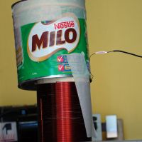
The Tesla coil is my junk coil running on half of a 12kV 30mA NST. It has a few ceramic caps and a 3 segment static gap. Primary is 15 turns and secondary is 260 turns in 11 inches. There is usually no toroid but I used one to intensify the sparks by putting an old tin on top.
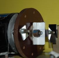
The motor and first surface mirror is as shown and rotates at about 2900 RPM. It is a synchronous motor with ground flats that doesnt quite sync at 3000 RPM with the extra load.
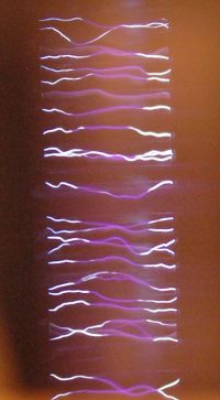
Mirror to spark distance is 38cm which means that the image moves at about 100m/s. The picture represents about 2cm width and 4cm height ie vertical scale is 40us. (just over 100ns/pixel)
So what do we see and how to interpret it?
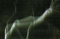
There is a ladder of sparks with each spark being fairly discrete and without any obvious parallel sparks. All sparks seem complete and there are no discontinuities. Almost all sparks are bright at the ends but less bright in the centre third. This also corresponds with what you see when it is running. I am not sure what it means, however, if each spark is a single cycle then the negative one third may brighter each half cycle, leaving the centre dim.
Peter
Re: High speed Tesla spark photos
HV Enthusiast, Wed Sept 06 2006, 02:39PM
Could you explain in more detail how the mirror works and how you are capturing the arcs image in a brief period of time? With a rotating mirror, i can't see how that is occuring especially considering that the minimum shutter duration for your camera is only 125us and you are actually using a shutter speed of 1/2 second.
I would think you would only want to rotate the mirror once extremely fast to capture a brief period of time as continously spinning the mirror will just integrate the image over the full 1/2 second as opposed to capturing say only a 5us fragment.
Re: High speed Tesla spark photos
Tesladownunder, Wed Sept 06 2006, 04:00PM
The mirror spreads the image over time and due to the mirrors speed, it will only show a 4cm section out of each circumference of 2*pi*38cm = 238cm. This means that only 4/238 = 1.7% of the time is the mirror aligned to allow a spark image to the camera. It is however travelling at 238cm*2900RPM = 238*48cm/s=11500cm/s. It will do this repeatedly over the duration that the shutter is open.
Typically with camera shutter speeds of perhaps 1/10 sec you only get to see single sparks. This is 4.8 mirror rotations only with a 1.7% chance of hitting a given spark. About even odds for a 10Hz spark.
I did do some 1/400 shutter speeds and never saw a spark once in about 10 shots.
Each spark image will be overlaid but if there are few enough, then they won't overlap too much.
So no, this isnt a high speed shutter but a way of introducing a high speed time axis to events. If it were looking at stepped leaders and other lightning stuff, it would be very interesting as the spark crosses from left to right in a stepwise manner.
I need to try this on a bigger TC to show the banjo effect, and perhaps on a DC spark through an inductor to show the spark develop into an arc. As it is these small TC sparks are too small and fast to show structure on a microsecond timescale.
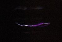
Pic shows a typical single spark seen with a 1/10 exposure and slow TC firing rate.
Peter
Tesladownunder, Wed Sept 06 2006, 04:00PM
EastVoltResearc wrote ...
Could you explain in more detail how the mirror works and how you are capturing the arcs image in a brief period of time? With a rotating mirror, i can't see how that is occuring especially considering that the minimum shutter duration for your camera is only 125us and you are actually using a shutter speed of 1/2 second.
I would think you would only want to rotate the mirror once extremely fast to capture a brief period of time as continously spinning the mirror will just integrate the image over the full 1/2 second as opposed to capturing say only a 5us fragment.
The mirror spreads the image over time and due to the mirrors speed, it will only show a 4cm section out of each circumference of 2*pi*38cm = 238cm. This means that only 4/238 = 1.7% of the time is the mirror aligned to allow a spark image to the camera. It is however travelling at 238cm*2900RPM = 238*48cm/s=11500cm/s. It will do this repeatedly over the duration that the shutter is open.
Typically with camera shutter speeds of perhaps 1/10 sec you only get to see single sparks. This is 4.8 mirror rotations only with a 1.7% chance of hitting a given spark. About even odds for a 10Hz spark.
I did do some 1/400 shutter speeds and never saw a spark once in about 10 shots.
Each spark image will be overlaid but if there are few enough, then they won't overlap too much.
So no, this isnt a high speed shutter but a way of introducing a high speed time axis to events. If it were looking at stepped leaders and other lightning stuff, it would be very interesting as the spark crosses from left to right in a stepwise manner.
I need to try this on a bigger TC to show the banjo effect, and perhaps on a DC spark through an inductor to show the spark develop into an arc. As it is these small TC sparks are too small and fast to show structure on a microsecond timescale.
Pic shows a typical single spark seen with a 1/10 exposure and slow TC firing rate.
Peter

Re: High speed Tesla spark photos
Terry Fritz, Thu Sept 07 2006, 10:36PM
Very cool Peter!!
This is like the "streak" cameras used to see high speed arcs, but your pictures are 1000X better than other pictures like this I have seen!! Probably due to them being old film based things developed by people that had no idea what they were doing :o) The very high speed arc makes the pictures very nice to as opposed to things that a streak camera really blures out.
Apparently, old laser printers also have a very nice eight sided front surface mirror on a stepper motor. It scans the laser beam across the paper. I guess you could just mount the camera so the mirror would reflect the coil's arcs... With rechargable digital cameras, one does not have to worry about wasting 10,000 pictures now
I was going to try it once but it all seemed to messy. However, you have shown it to be easy after all!! It would be very cool to see streamer growth with this method!!
Dan - Imagine if the camera were spinning and you took a picture of the arc. The fast arcs would be recorded one after another next to each other on the film. Since the arc is "moving", the small sub oscillations are recorded next to each other in a row. Since the arcs are sharp bright and fast, they each show up clearly as opposed to being a long blur. I tried to find a nice explanation on the net, but they are all goofy high level crap... In out case we don't need a slit or anything like that.
The pictures are normally only good for a "thin line" of sight smeared arcoss the film. But the sparks take care of that for us in this special case
Cheers,
Terry
Terry Fritz, Thu Sept 07 2006, 10:36PM
Very cool Peter!!
This is like the "streak" cameras used to see high speed arcs, but your pictures are 1000X better than other pictures like this I have seen!! Probably due to them being old film based things developed by people that had no idea what they were doing :o) The very high speed arc makes the pictures very nice to as opposed to things that a streak camera really blures out.
Apparently, old laser printers also have a very nice eight sided front surface mirror on a stepper motor. It scans the laser beam across the paper. I guess you could just mount the camera so the mirror would reflect the coil's arcs... With rechargable digital cameras, one does not have to worry about wasting 10,000 pictures now

I was going to try it once but it all seemed to messy. However, you have shown it to be easy after all!! It would be very cool to see streamer growth with this method!!
Dan - Imagine if the camera were spinning and you took a picture of the arc. The fast arcs would be recorded one after another next to each other on the film. Since the arc is "moving", the small sub oscillations are recorded next to each other in a row. Since the arcs are sharp bright and fast, they each show up clearly as opposed to being a long blur. I tried to find a nice explanation on the net, but they are all goofy high level crap... In out case we don't need a slit or anything like that.
The pictures are normally only good for a "thin line" of sight smeared arcoss the film. But the sparks take care of that for us in this special case

Cheers,
Terry
Re: High speed Tesla spark photos
Tesladownunder, Fri Sept 08 2006, 01:24AM
 And you dont have to hold them down...
The related threads on this topic that I started that got me here are "End-on spark view - broken sparks" and "High speed spark photography".
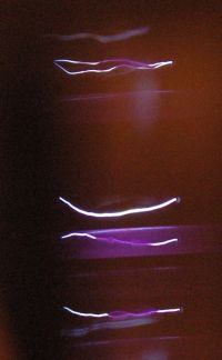
The pic shows how the less bright middle section feathers out with small streamers sometimes. The very flat lines are edge of mirror effects.
Peter
Tesladownunder, Fri Sept 08 2006, 01:24AM
Terry Fritz wrote ...
This is like the "streak" cameras used to see high speed arcs, but your pictures are 1000X better than other pictures like this I have seen!! Probably due to them being old film based things developed by people that had no idea what they were doing :o) The very high speed arc makes the pictures very nice to as opposed to things that a streak camera really blures out.
I hadn't heard of "streak" cameras before. Doing this with film would have been a real pain. As it is. my mirror is too small to allow my camera to autofocus and manual focus is not accurate enough. I would like to increase spark intensity and length and push the boundaries in regard to speed. My motor is awfully unbalanced with the mirror despite a small counterweight so I have to physically hold it down to prevent it going out of alignment while it picks up speed.This is like the "streak" cameras used to see high speed arcs, but your pictures are 1000X better than other pictures like this I have seen!! Probably due to them being old film based things developed by people that had no idea what they were doing :o) The very high speed arc makes the pictures very nice to as opposed to things that a streak camera really blures out.
Terry Fritz wrote ...
Apparently, old laser printers also have a very nice eight sided front surface mirror on a stepper motor.
I used on of those in a laser scanner project just recently. The mirror is only a few mm wide but they are accurate first surface mirrors and you get 8 times the chance to see a spark Apparently, old laser printers also have a very nice eight sided front surface mirror on a stepper motor.
 And you dont have to hold them down...
Terry Fritz wrote ...
I was going to try it once but it all seemed to messy. However, you have shown it to be easy after all!! It would be very cool to see streamer growth with this method!!
The pictures are normally only good for a "thin line" of sight smeared arcoss the film. But the sparks take care of that for us in this special case
I would like to increase to speed/distance of the spark from the mirror although I need to maintain distance between the spark and the camera so I might need to change the setup to a vertical one. so the mirror will reflect at 90 degrees rather than only 20 or so.I was going to try it once but it all seemed to messy. However, you have shown it to be easy after all!! It would be very cool to see streamer growth with this method!!
The pictures are normally only good for a "thin line" of sight smeared arcoss the film. But the sparks take care of that for us in this special case

The related threads on this topic that I started that got me here are "End-on spark view - broken sparks" and "High speed spark photography".
The pic shows how the less bright middle section feathers out with small streamers sometimes. The very flat lines are edge of mirror effects.
Peter

Re: High speed Tesla spark photos
Sulaiman, Fri Sept 08 2006, 08:19AM
Peter,
as I'm sure you realise - you must stop this line of investigation immediately
If not you will reduce Tesla Coil design to
A) Choose input power
B) Choose ark type desired
crunch-crunch-crunch ........
The design for your coil is ...............
That would be boring - so for the sake of the TC community
secrets of the arc must remain secret
stop now before it's too late!
YOU HAVE BEEN WARNED
Sulaiman, Fri Sept 08 2006, 08:19AM
Peter,
as I'm sure you realise - you must stop this line of investigation immediately

If not you will reduce Tesla Coil design to
A) Choose input power
B) Choose ark type desired
crunch-crunch-crunch ........
The design for your coil is ...............
That would be boring - so for the sake of the TC community
secrets of the arc must remain secret
stop now before it's too late!
YOU HAVE BEEN WARNED
Re: High speed Tesla spark photos
Tesladownunder, Fri Sept 08 2006, 07:31PM
But there will always be the dark gap to make sure this remains a Dark Art....
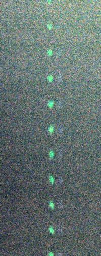
I have now done a LED calibration which shows my geometry is a bit out.
Nevertheless with the motor in sync at 3000RPM (better balancing), and two LED's at 2.9m running at 100kHz, this is the result. The green LED is brightest and a white LED beside it is an older type and not very bright. The 100kHz is a square wave but the op amp gain drops off markedly so it might be a bit sinusoidal. I need to check it on a CRO.
Nevertheless there are 10 flashes in 1100 pixels at 100kHz. ie One cycle of 110 pixels occurs in 10us. Each pixel represents about 100ns.
Peter
Tesladownunder, Fri Sept 08 2006, 07:31PM
Sulaiman wrote ...
.. secrets of the arc must remain secret
stop now before it's too late!
LOL.. secrets of the arc must remain secret
stop now before it's too late!
But there will always be the dark gap to make sure this remains a Dark Art....
I have now done a LED calibration which shows my geometry is a bit out.
Nevertheless with the motor in sync at 3000RPM (better balancing), and two LED's at 2.9m running at 100kHz, this is the result. The green LED is brightest and a white LED beside it is an older type and not very bright. The 100kHz is a square wave but the op amp gain drops off markedly so it might be a bit sinusoidal. I need to check it on a CRO.
Nevertheless there are 10 flashes in 1100 pixels at 100kHz. ie One cycle of 110 pixels occurs in 10us. Each pixel represents about 100ns.
Peter

Re: High speed Tesla spark photos
Terry Fritz, Fri Sept 08 2006, 07:38PM
Hi TDU,
Focus is an interesting thought. I am thinking that (for a Tesla coil) the distance would be say 5 to 10 feet so that helps. I will have to look at my cameras to see if they have any other settings besides "auto"
An 8 sided mirror would be nice since the probablitlity of the thing being in frame are 8 times higher. But your right about the very thin mirrors (nice scanner project you did BTW ).
).
A am thinking of taking a small block and drilling and pressing a shaft through it. Then one could accurately mill off four flats on it in relation to the shaft. Then one could slobber glue all over it to hold the mirrors on and mess up the ballance But the block could also be easily drilled for setscrews for ballancing weight. Then you would have a pretty easy to make four sided mirror that would be pretty well ballanced.
Then, you could hook it to a high speed motor somehow and spin it really fast till the mirrors fly off into the camera lens to win one of those photography versions of the Darwin Awards Ok, it would need a lexan shield too
I don't think vibration would be a giant problem since everything happens so fast. It would be easy to put it all on a frame the could mount the camera too and then it would all go on a tripod. The motor could just be a plain DC one to make it simple since the speed would not be very critical at all. Some parts would have to be a bit massive while others are light.
I am not sure how fast it should or could turn. It would be cool to catch each cycle of a bang and see how the leader forms. "Theory" is that they form very quickly in relation to to top voltage of that cycle.
Cheers,
Terry
Terry Fritz, Fri Sept 08 2006, 07:38PM
Hi TDU,
Focus is an interesting thought. I am thinking that (for a Tesla coil) the distance would be say 5 to 10 feet so that helps. I will have to look at my cameras to see if they have any other settings besides "auto"

An 8 sided mirror would be nice since the probablitlity of the thing being in frame are 8 times higher. But your right about the very thin mirrors (nice scanner project you did BTW
 ).
).A am thinking of taking a small block and drilling and pressing a shaft through it. Then one could accurately mill off four flats on it in relation to the shaft. Then one could slobber glue all over it to hold the mirrors on and mess up the ballance
 But the block could also be easily drilled for setscrews for ballancing weight. Then you would have a pretty easy to make four sided mirror that would be pretty well ballanced.
Then, you could hook it to a high speed motor somehow and spin it really fast till the mirrors fly off into the camera lens to win one of those photography versions of the Darwin Awards
 Ok, it would need a lexan shield too
I don't think vibration would be a giant problem since everything happens so fast. It would be easy to put it all on a frame the could mount the camera too and then it would all go on a tripod. The motor could just be a plain DC one to make it simple since the speed would not be very critical at all. Some parts would have to be a bit massive while others are light.
I am not sure how fast it should or could turn. It would be cool to catch each cycle of a bang and see how the leader forms. "Theory" is that they form very quickly in relation to to top voltage of that cycle.
Cheers,
Terry
Re: High speed Tesla spark photos
Tesladownunder, Sun Sept 10 2006, 12:10PM
Well there was a break in the weather so I go to set everything up to run the TC.
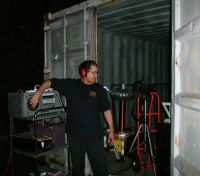
The TC is my 4 inch one. I'll look up the details later but it was set up for 4 then 6 inch sparks between pointed electrodes to a grounded object. Power was 4 MOT's and current draw about 10A 250 V so enough to have a reasonable power arc rise in the centre if it got going.
The distance from camera lens to mirror was 30cm and from mirror to TC 140 cm. First two pics show the setup (obviously taken with my older camera).
Third pic shows the through the non-rotating mirror showing the toroid on the left with the reversed image.
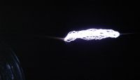
Fourth pic shows a single spark with a series of up to 5 parallel sparks. Each space between sparks is 50 pixels which going by the photos before is 5us period or 200kHz. This implies a 100kHz waveform if there are two sparks per sine wave. Seems in the ballpark.
Note that this is not the Banjo effect seen on a windy day which is just the spark gap firing rate of 100/120Hz for a synch gap (or 1100Hz with my fast asynch gap which was running flat out as I didn't have a third variac setup). This is 100 - 1000 times faster.
I've taken a few hundred shots in the last few days (and lots of blanks) so there is a lot more there.
I have not investigated streamers yet.
Comments? Has anyone done this before?
Peter


Re: High speed Tesla spark photos
Terry Fritz, Sun Sept 10 2006, 06:36PM
Hi TDU,
WOW!!!!

That is wonderful!!!
As far as I know, these are the first high speed streamer pictures like this!!! We have often wished, but never have "had" them before!!
I PDFed some stuff about streak cameras and using them for high voltage arcs from Bazelyan and Raizer here (3MB):

But they are using slits and all so their stuff is sort of fuzzy (the pictures are that bad ). But yours are beautiful!! I am working on getting parts for mine
This is probably the most important tool to come along in years for Tesla coil studies!!!
Cheers,
Terry
Terry Fritz, Sun Sept 10 2006, 06:36PM
Hi TDU,
WOW!!!!


That is wonderful!!!
As far as I know, these are the first high speed streamer pictures like this!!! We have often wished, but never have "had" them before!!
I PDFed some stuff about streak cameras and using them for high voltage arcs from Bazelyan and Raizer here (3MB):

But they are using slits and all so their stuff is sort of fuzzy (the pictures are that bad
 ). But yours are beautiful!! I am working on getting parts for mine
This is probably the most important tool to come along in years for Tesla coil studies!!!
Cheers,
Terry
Re: High speed Tesla spark photos
Steve Conner, Sun Sept 10 2006, 11:05PM
Excellent stuff TDU!

 Can we see a picture of an air streamer?
BTW, I'm sure it says in the Colorado Springs Notes "Must examine sparks with rotating mirror" but Tesla never got round to it, and neither did anyone else that I know of
Steve Conner, Sun Sept 10 2006, 11:05PM
Excellent stuff TDU!


 Can we see a picture of an air streamer?
BTW, I'm sure it says in the Colorado Springs Notes "Must examine sparks with rotating mirror" but Tesla never got round to it, and neither did anyone else that I know of

Re: High speed Tesla spark photos
Tesladownunder, Mon Sept 11 2006, 01:01AM
The streak photography article is fascinating. It is also about 3 orders of magnitude faster than what I am doing and requires a photomultiplier tube to amplify it. It gives propagation rates of leaders of 10^9 cm/sec (approx 1/30 of speed of light) whereas I can only achieve 10^4 cm/sec.
Still, I was never expecting to be able to see things like that with equipment found around the home.
On the other hand, streamer growth has structure on very slow timescales which is why they are interesting to look at. In short, you can see them move so there are things happening at all sorts of timeframes from nanoseconds to seconds. Streamer brightness is much lower however but should register some interesting images.
Interpretation of streak camera stuff is easy if sparks are a straight line but become difficult if angled or branched so a blurred mess is a possible outcome when I try this with streamers.
I'm not sure how "useful" this will be but I hope to get some streamer data sometime.
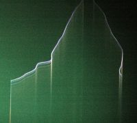
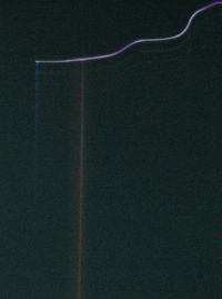
The photo (one of my "mystery" photos) shows that the smear of light in the path of the spark is an artifact since it disappears when the spark is out of the top of the screen. I am not sure if this is due to mirror edge effects, or is a lens flare or camera UV issue. The green colour is a result of auto exposure and probably auto white balance when the software processes purple sparks.
Peter

Re: High speed Tesla spark photos
Terry Fritz, Mon Sept 11 2006, 03:15AM
Hi Peter,
There is another photo from the book here that shows continuous and flash mode streak pics:

Super fancy streak cameras can do <2pS and some laboratory thngs are into the femto seconds!! I am not sure much "moves" in that case


Pie-in-the-sky stuff for "us", but maybe we can learn some tricks from them.
Before Tesla was born, John Tyndall was doing the expiriment described here with moving a mirror or turning of one's head quickly.


I have a 1860's physics book (lost at the moment) that shows how to use a funnel with a paper diaphram with a bunsen burner to modulate the flame and use a spinning mirror to "see" the sound waves... I am sure Tesla was familiar with this but I am not sure here ever tried it. He probably though the events were too fast to see. Or, he did try it and could not get it to work given the time and equipment he had.
The leaders in the book are made with a Marx generator I think so they are different than ours. Tesla coil leaders might be much slower since they ride the ~100kHz sine wave of the secondary as opposed to being a giant cap discarge thing. We can look and see now
The "smear of light" you mention is where the camera is looking down the leader from the end thus it appears to have a bright area in it. People commonly mistake these for ball lighting in standard arc photos.


You picture seems completely true to me. You can probably "fix" the white ballance on your camera which might help the colors if you don't already have enough camera settings to worry about
The bending of the arcs just makes the pictures more "interesting" since we can argue for years as to how that affects the pictures
Great stuff!!
Probably be a whole week or two before I can get all the parts for mine and get it going
Cheers,
Terry
Terry Fritz, Mon Sept 11 2006, 03:15AM
Hi Peter,
There is another photo from the book here that shows continuous and flash mode streak pics:

Super fancy streak cameras can do <2pS and some laboratory thngs are into the femto seconds!!
 I am not sure much "moves" in that case


Pie-in-the-sky stuff for "us", but maybe we can learn some tricks from them.
Before Tesla was born, John Tyndall was doing the expiriment described here with moving a mirror or turning of one's head quickly.


I have a 1860's physics book (lost at the moment) that shows how to use a funnel with a paper diaphram with a bunsen burner to modulate the flame and use a spinning mirror to "see" the sound waves... I am sure Tesla was familiar with this but I am not sure here ever tried it. He probably though the events were too fast to see. Or, he did try it and could not get it to work given the time and equipment he had.
The leaders in the book are made with a Marx generator I think so they are different than ours. Tesla coil leaders might be much slower since they ride the ~100kHz sine wave of the secondary as opposed to being a giant cap discarge thing. We can look and see now

The "smear of light" you mention is where the camera is looking down the leader from the end thus it appears to have a bright area in it. People commonly mistake these for ball lighting in standard arc photos.


You picture seems completely true to me. You can probably "fix" the white ballance on your camera which might help the colors if you don't already have enough camera settings to worry about

The bending of the arcs just makes the pictures more "interesting" since we can argue for years as to how that affects the pictures

Great stuff!!
Probably be a whole week or two before I can get all the parts for mine and get it going

Cheers,
Terry
Re: High speed Tesla spark photos
Tesladownunder, Mon Sept 11 2006, 11:09PM
Terry has a nice setup (see the next post). It should have a good chance of working well and it has a lot more design about it than my unbalanced shaft and small mirror. Having the camera nice and close is a big plus and the lexan shield is close enough to the lens not to worry about internal reflections.
I'm not sure the ISO is really increased by 4 times since you are just increasing your chance of catching a single event in the mirror by 4 times.
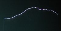
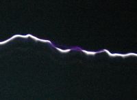
A few more pics for comment
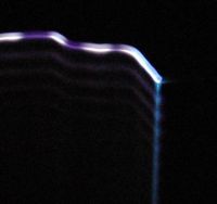
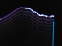
Photo 1 shows that sometimes the spark has no following ringdown sparks.
Photo 2 shows some mild ringdown only.
Photo 3 shows the bright white arc channel interrupted with faint purple arcs.
Photo 4 shows detail of the initial spark which has a well defined bright central channel on the enlarged view.
Photo 5 shows the ionization around the stainless steel electrode which does glow red hot at the end of a run although that is too faint to see.
Photo 6 shows that the ionization is sometimes delayed by 5 us after the initial spark strikes.
Photo7 shows an unusual streak that I suspect is the spark channel hitting a dust mote and burning it up.


Re: High speed Tesla spark photos
Terry Fritz, Mon Sept 11 2006, 11:36PM
Hi,
I got the motor and mirrors ordered for my streak camera. I also made the frame, mounted the parts, and machined an aluminum block to hole the mirrors. Here is the camera system so far:


Just simple wood construction. The bottom has a tripod 1/4-20 adaptor for my heavy tripod. The big pillow block will hold the motor. The aluminum cube will have the mirrors expoxied to it and then it will be pressed on the motor shaft. The lexan shield protects the camera in case it blows apart. There is a 1/4-20 brass bolt on the bottom of the camera and spacer with a wing nut to hold the camera to the base. Took about two hours to build up.
Here is a picture (850k) through the camera as mounted:

So just need to drill the block for the motor shaft and press it on and glue the mirrors in place.
It should do 0.5in/uS at 20,000 RPM at ten feet. So a 100kHz coil should have the + - cycles separated buy 2.5 inches at full speed. With four mirrors and having the camera so close it should have a wide field of view so I don't have to take 10,000 pictures
The camera has manual zoom, focus and ISO (100,200,400) settings and has 2048 x 1536 pixels. At 24000 RPM that is 400 RPS or four frames so the ISO really should be 1600. But I think a friends camera will do that if it turns out to be a problem. The mount is easy to adjust to any camera with a drill and saw
Should be cool!!
For Peter's pictures:
I wonder if the hot streamer arc channel was alread in place. Or it might have just gone in one shot like a Marx spark. It does seem more streaked at the right if that is were the spark began.
I would think the dim part would be the ring "up" and then the arc would drain the system and be dark immediately after that.
I have no idea!! Maybe the dim parts happen to be hotter and more conductive.
Interesting that the ionization is fairly constant as one would expect
Super cool! Prolly far more questions than answers
Cheers,
Terry
Terry Fritz, Mon Sept 11 2006, 11:36PM
Hi,
I got the motor and mirrors ordered for my streak camera. I also made the frame, mounted the parts, and machined an aluminum block to hole the mirrors. Here is the camera system so far:


Just simple wood construction. The bottom has a tripod 1/4-20 adaptor for my heavy tripod. The big pillow block will hold the motor. The aluminum cube will have the mirrors expoxied to it and then it will be pressed on the motor shaft. The lexan shield protects the camera in case it blows apart. There is a 1/4-20 brass bolt on the bottom of the camera and spacer with a wing nut to hold the camera to the base. Took about two hours to build up.
Here is a picture (850k) through the camera as mounted:

So just need to drill the block for the motor shaft and press it on and glue the mirrors in place.
It should do 0.5in/uS at 20,000 RPM at ten feet. So a 100kHz coil should have the + - cycles separated buy 2.5 inches at full speed. With four mirrors and having the camera so close it should have a wide field of view so I don't have to take 10,000 pictures

The camera has manual zoom, focus and ISO (100,200,400) settings and has 2048 x 1536 pixels. At 24000 RPM that is 400 RPS or four frames so the ISO really should be 1600. But I think a friends camera will do that if it turns out to be a problem. The mount is easy to adjust to any camera with a drill and saw

Should be cool!!
For Peter's pictures:
Photo 1 shows that sometimes the spark has no following ringdown sparks.
I wonder if the hot streamer arc channel was alread in place. Or it might have just gone in one shot like a Marx spark. It does seem more streaked at the right if that is were the spark began.
Photo 2 shows some mild ringdown only.
I would think the dim part would be the ring "up" and then the arc would drain the system and be dark immediately after that.
Photo 3 shows the bright white arc channel interrupted with faint purple arcs.
I have no idea!! Maybe the dim parts happen to be hotter and more conductive.
Photo 5 shows the ionization around the stainless steel electrode
Interesting that the ionization is fairly constant as one would expect

Super cool! Prolly far more questions than answers

Cheers,
Terry
Re: High speed Tesla spark photos
Bert, Wed Sept 13 2006, 03:33PM
Terry and Peter,
It appears that the direction of increasing time is downward, not upward.
Peter can you confirm?
Bert
Bert, Wed Sept 13 2006, 03:33PM
Terry and Peter,
It appears that the direction of increasing time is downward, not upward.
Peter can you confirm?
Bert
Re: High speed Tesla spark photos
Tesladownunder, Wed Sept 13 2006, 06:09PM
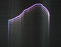
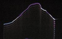
Yes. The bright spark at the top is the initial one, then the next 5 or so progressively weaker sparks below are subsequent events so down is advancing time.
With this photo I have increased the contrast to show two things.
Firstly that there are two types of electrode glow on the right with the greenish one appearing only after a few cycles.
Secondly, look closely at the ringdown sparks at the left. The space between the sparks is not empty but shows another line in between. I wonder if this is a second harmonic.
Peter

Re: High speed Tesla spark photos
Terry Fritz, Wed Sept 13 2006, 09:38PM
Hi,
Ok... This is what I thought was going on which is apparently wrong:

This is a pretty typical top voltage of a coil when an arc reaches ground:

So this should be the correct situatiion now.

Cheers,
Terry
Terry Fritz, Wed Sept 13 2006, 09:38PM
Hi,
Yes. The bright spark at the top is the initial one, then the next 5 or so progressively weaker sparks below are subsequent events so down is advancing time.
Ok... This is what I thought was going on which is apparently wrong:

This is a pretty typical top voltage of a coil when an arc reaches ground:

So this should be the correct situatiion now.

Cheers,
Terry
Re: High speed Tesla spark photos
Tesladownunder, Sat Sept 16 2006, 11:56AM
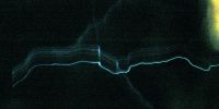
Here is the "first" streamer picture which forms an arc that hits.
Pic is of about 12 inches of an 18 inch spark from the toroid side on the left. I was throttling the variac back to try to just get streamers and few hits.
It is quite different. Time axis is downward. The initial streamer sparks (the top one) can be broken into perhaps 6 consecutive channels (5us apart = 2 pulses per 100kHz). Although it is difficult to be sure, only the last one makes it across the screen then a 10us gap then the main arc hits. Interestingly there is no ring down on the main arc, however the distances are greater and intensity is down.
I've taken lots of black shots with information on them but need to process them.
I guess the new information from the rotating mirror stuff is that streamers enlarge with successive cycles and ring up leading to a spark that connects. Sparks that connect (often) have a ring down. Not really unexpected from the CRO pics but nice to see it directly. So streamers ring up and sparks ring down - easy to remember.
First pic shows the streamer with ring up then an arc connects. The yellow blur on the right is my kitchen window seen through the mirror when it is horizontal and mostly out of view.
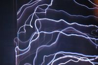
Second pic is lots of overlapping sparks just for fun. Conventional sparks to a grounded object like I have shown before with the ringdown visible. The sparks are somewhat out of focus at the bottom of the pic.
Peter


Re: High speed Tesla spark photos
Terry Fritz, Sat Sept 16 2006, 03:50PM
Hi Peter,
I enhanced and commented it here:

You can see every known leader phenomena in it!!!!
Here is a reference from Bazelyan/Raizer.

It looks like the leader tip stalls a bit probably as that cycle reverses and cuts off the power. The next cycle reheats it and eventually it goes onward and breifly stalls again.
Amazingly, you can see the streamer branches(!!!) at the very tip on the right where it is darker.
That is a hit or miss thing. Often the power is totally removed from the streamer so the arc is dead right there. Models predict that based on stuff that still needs to be studied. It is probably fairly consistant (if it will occur or not) with a given coil setup.
 Looking forward to more!!!
This is fantastic stuff!!! Your pictures are some of the best available of any leader arc and probably far better!!!
Cheers,
Terry
Terry Fritz, Sat Sept 16 2006, 03:50PM
Hi Peter,
Here is the "first" streamer picture which forms an arc that hits.What a stunning picture!!!!!!!!!
I enhanced and commented it here:

You can see every known leader phenomena in it!!!!
Here is a reference from Bazelyan/Raizer.

It looks like the leader tip stalls a bit probably as that cycle reverses and cuts off the power. The next cycle reheats it and eventually it goes onward and breifly stalls again.
Amazingly, you can see the streamer branches(!!!) at the very tip on the right where it is darker.
Interestingly there is no ring down on the main arc
That is a hit or miss thing. Often the power is totally removed from the streamer so the arc is dead right there. Models predict that based on stuff that still needs to be studied. It is probably fairly consistant (if it will occur or not) with a given coil setup.
I've taken lots of black shots with information on them but need to process them.
 Looking forward to more!!!
This is fantastic stuff!!! Your pictures are some of the best available of any leader arc and probably far better!!!
Cheers,
Terry
Re: High speed Tesla spark photos
Tesladownunder, Sun Sept 17 2006, 06:53AM
The second leader tip that you indicate on the right occurs where a streamer branches. Again there is streamer overlap.
In both cases the streamer channel continues although all the 4 or 5 channels may be "stepped" so it looks like one or two were stopped.
The diagrams from Bazelyan/Raizer, while not well labelled with time axes, indicate much faster events analysing what happens within the first strike that I just see as a single event.
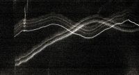
Pic #1 below shows variation in the intensity of each ring up spark channel.
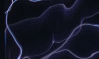
Pic #2 below shows tthe two most central sparks of similar intensity. Can you tell which is a streamer and which is a spark? (Sparks ring down and streamers ring up) On the full photo the streamer fades but the spark doesn't.
Pic #3 Shows many streamer channels
Peter
Tesladownunder, Sun Sept 17 2006, 06:53AM
Terry Fritz wrote ...
... I enhanced and commented it here:

You can see every known leader phenomena in it!!!!
Here is a reference from Bazelyan/Raizer.

It looks like the leader tip stalls a bit probably as that cycle reverses and cuts off the power. The next cycle reheats it and eventually it goes onward and breifly stalls again....
I don't think these are leader tips and my interpretation is a little different. What you have labelled as the leader tip on the left looks to me like a simple change in direction for the spark. In the two dimensions we see it in there is a sudden change in direction downwards. This will overlap the streamers and make that area bright. If the area is much brighter than expected (as it appears to be visually) then this is due to a third dimensional effect, ie the spark goes in or out of the plane of view for a distance which will relate to the perceived brightness.... I enhanced and commented it here:

You can see every known leader phenomena in it!!!!
Here is a reference from Bazelyan/Raizer.

It looks like the leader tip stalls a bit probably as that cycle reverses and cuts off the power. The next cycle reheats it and eventually it goes onward and breifly stalls again....
The second leader tip that you indicate on the right occurs where a streamer branches. Again there is streamer overlap.
In both cases the streamer channel continues although all the 4 or 5 channels may be "stepped" so it looks like one or two were stopped.
The diagrams from Bazelyan/Raizer, while not well labelled with time axes, indicate much faster events analysing what happens within the first strike that I just see as a single event.
Terry Fritz wrote ...
That is a hit or miss thing. Often the power is totally removed from the streamer so the arc is dead right there. Models predict that based on stuff that still needs to be studied. It is probably fairly consistant (if it will occur or not) with a given coil setup.
The presence or absence of ring down is seen in different sparks in the same photo in the (second photo in my last post) so it is not just a coil setup issue. I would have thought that it is hard to remove all energy in one cycle from a resonant circuit without some ringing.Interestingly there is no ring down on the main arc
That is a hit or miss thing. Often the power is totally removed from the streamer so the arc is dead right there. Models predict that based on stuff that still needs to be studied. It is probably fairly consistant (if it will occur or not) with a given coil setup.
Pic #1 below shows variation in the intensity of each ring up spark channel.
Pic #2 below shows tthe two most central sparks of similar intensity. Can you tell which is a streamer and which is a spark? (Sparks ring down and streamers ring up) On the full photo the streamer fades but the spark doesn't.
Pic #3 Shows many streamer channels
Peter


Re: High speed Tesla spark photos
Terry Fritz, Tue Sept 19 2006, 02:48AM
Hi All,
It works!!


Here are the setup details before I forget them
Zoom - To fit the image nicely to the picture. Does not seem to affect light gathering. Optical zoom only as opposed to stupid software zoom.
Shutter speed - Does not matter much. Long enough that you get a good chance of "catching" an arc. 1/10 and 1/20 sec does well here.
Background sensor noise - Don't worry about trying to fix noise by subtraction of a dark frame or anything. Oddly, that seems to hurt more than help. If your camera does this automatically, I think it should be turned off. The key is a sensitive low noise sensor to begin with!!
Aperture - As big as possible!! You need to gather as much light as you possibly can at all costs!!
Len's - If you have a choice, one that gathers the most light.
ISO - As high as possible!!! 1,000,000 would be nice!!! Mine only goes to 400 at that is barely enough. One of those cameras that can be forced up to 16,000 whether it is good or not would be nice. You really need this one!!! As Dan and other's say, getting data out of the camera in a deep RAW format would really help here too. The cool stuff is just barely above the noise level in my case.
Distance - As close as possible just to gather more light!!
Speed - My four rotating mirror block is running at about 5000 RPM. 2000 - 6000 RPM would be fine. I think slower is a bit better since more light hits the sensor pixels that way, but you want it to be fast enough to separate the pulses.
The room should be very dark to eliminate stray light.
Flash - Be sure to turn that **^*&%* thing off!!! There you are in the dark fiddling with the camera and blammo!! Almost knocked me over.
Remote shutter is ultra nice!! If the camera can take pictures automatically at say every second that would be very nice too. But you can do the shutter button too.
White Balance - I used daylight, but it is turning out black and white mostly in my case as I super pump up the brightness and contrast.
EV - Set it up high to brighten the picture as much as possible, but it had no effect in my camera's manual mode.
Reset - Set the camera so it does not loose all the settings when the power is turned off
Focus - Manual. I just measured it and set the camera to that distance. This could be tricky, but I did not have much trouble with it.
Background - Black felt works fine.
I took about 200 pictures today. Mostly figuring out by trial and error what is good. Rechargeable batteries are good too but you don't use the flash so the battery drain is pretty low. I did keep the LCD screen on all the time.
At 5000 RPM you can just glue the mirror to the little motor shaft or whatever. No need for a fancy machined block. No need for four mirrors, just one would do fine with a longer shutter speed to catch a good arc on one of the rotations.
The stray light paths near the mirror should be blocked and all the surfaces should be painted black to eliminate stray light reflections.
So it is pretty easy. I did have to carefully increase brightness and contrast with software to see air streamers. They are barely above the noise level. However, power arcs are very easy to see. I had to go back to all the black frames and lighten them so see if there were air streamers. Power arcs show up right away.
I put a 40.5MB zip file with a lot of pictures here:

At the bottom of the page select "free".
It makes you wait about 2 minutes to read the ads and then a download screen comes up.
Enter the funny letters in the robot trap box and save the file. It is just a typical zip file filled with all the JPG images from the last "lucky run". Some are plain and some have been enhanced. Some of those pictures are just black too... The four read streaks to the left or the calibration LED flashing at 100kHz. Each mirror makes it's own streak depending on the fine alignment of the mirror. If the pulses are blurred out, it is because that mirror scanned twice while the shutter was open.
I "think" time increases from bottom to top. Hard to say since the camera is upside down, inverted, twisted, and the motor turns in some direction... "Hard to say for sure" #;-)) I will try to modify the calibrator so it gradually goes out to point in the right direction. The calibrator is not really needed but it does prove the speed and all.
Thanks to Peter for figuring all this out!!! I think you are even working on an improvement )
)
I don't know what the pictures "mean" yet since Just taking the pictures is the deal right now.
Cheers,
Terry
To follow up...
I modified the calibrator for 1uS on time pulses at 100kHz but with a diode and cap so it has a "tail" to point in the direction of time.

So time so increasing from the bottom, toward to top in my pictures.
This is most interesting ))
))
I took one good frame and enhanced it with comments (1.7MB to preserve all the detail):

You can see each ring up pulse now!!!!!!!!
The first pulse is very weak but visible.
The second pulse 5uS latter is stronger and has a significant downward branch but its upward branch almost goes 1/2 the distance.
The third pulse almost gets there and clearly stimulates streamers off the ground point.
The fourth pulse arcs and completes in a very bright area between the previous leader and the corona off the ground point.
Here is a ScanTesla equivalent:

This coil is highly predictable and the trailing oscillations are due to the leftover energy in the primary circuit. But those oscillations are weak in this case and do not show up at all in the photo.
Wild stuff!!!
Cheers,
Terry
Terry Fritz, Tue Sept 19 2006, 02:48AM
Hi All,
It works!!


Here are the setup details before I forget them

Zoom - To fit the image nicely to the picture. Does not seem to affect light gathering. Optical zoom only as opposed to stupid software zoom.
Shutter speed - Does not matter much. Long enough that you get a good chance of "catching" an arc. 1/10 and 1/20 sec does well here.
Background sensor noise - Don't worry about trying to fix noise by subtraction of a dark frame or anything. Oddly, that seems to hurt more than help. If your camera does this automatically, I think it should be turned off. The key is a sensitive low noise sensor to begin with!!
Aperture - As big as possible!! You need to gather as much light as you possibly can at all costs!!
Len's - If you have a choice, one that gathers the most light.
ISO - As high as possible!!! 1,000,000 would be nice!!! Mine only goes to 400 at that is barely enough. One of those cameras that can be forced up to 16,000 whether it is good or not would be nice. You really need this one!!! As Dan and other's say, getting data out of the camera in a deep RAW format would really help here too. The cool stuff is just barely above the noise level in my case.
Distance - As close as possible just to gather more light!!
Speed - My four rotating mirror block is running at about 5000 RPM. 2000 - 6000 RPM would be fine. I think slower is a bit better since more light hits the sensor pixels that way, but you want it to be fast enough to separate the pulses.
The room should be very dark to eliminate stray light.
Flash - Be sure to turn that **^*&%* thing off!!! There you are in the dark fiddling with the camera and blammo!! Almost knocked me over.
Remote shutter is ultra nice!! If the camera can take pictures automatically at say every second that would be very nice too. But you can do the shutter button too.
White Balance - I used daylight, but it is turning out black and white mostly in my case as I super pump up the brightness and contrast.
EV - Set it up high to brighten the picture as much as possible, but it had no effect in my camera's manual mode.
Reset - Set the camera so it does not loose all the settings when the power is turned off

Focus - Manual. I just measured it and set the camera to that distance. This could be tricky, but I did not have much trouble with it.
Background - Black felt works fine.
I took about 200 pictures today. Mostly figuring out by trial and error what is good. Rechargeable batteries are good too but you don't use the flash so the battery drain is pretty low. I did keep the LCD screen on all the time.
At 5000 RPM you can just glue the mirror to the little motor shaft or whatever. No need for a fancy machined block. No need for four mirrors, just one would do fine with a longer shutter speed to catch a good arc on one of the rotations.
The stray light paths near the mirror should be blocked and all the surfaces should be painted black to eliminate stray light reflections.
So it is pretty easy. I did have to carefully increase brightness and contrast with software to see air streamers. They are barely above the noise level. However, power arcs are very easy to see. I had to go back to all the black frames and lighten them so see if there were air streamers. Power arcs show up right away.
I put a 40.5MB zip file with a lot of pictures here:

At the bottom of the page select "free".
It makes you wait about 2 minutes to read the ads and then a download screen comes up.
Enter the funny letters in the robot trap box and save the file. It is just a typical zip file filled with all the JPG images from the last "lucky run". Some are plain and some have been enhanced. Some of those pictures are just black too... The four read streaks to the left or the calibration LED flashing at 100kHz. Each mirror makes it's own streak depending on the fine alignment of the mirror. If the pulses are blurred out, it is because that mirror scanned twice while the shutter was open.
I "think" time increases from bottom to top. Hard to say since the camera is upside down, inverted, twisted, and the motor turns in some direction... "Hard to say for sure" #;-)) I will try to modify the calibrator so it gradually goes out to point in the right direction. The calibrator is not really needed but it does prove the speed and all.
Thanks to Peter for figuring all this out!!! I think you are even working on an improvement
 )
)I don't know what the pictures "mean" yet since Just taking the pictures is the deal right now.
Cheers,
Terry
To follow up...
I modified the calibrator for 1uS on time pulses at 100kHz but with a diode and cap so it has a "tail" to point in the direction of time.

So time so increasing from the bottom, toward to top in my pictures.
This is most interesting
 ))
))I took one good frame and enhanced it with comments (1.7MB to preserve all the detail):

You can see each ring up pulse now!!!!!!!!
The first pulse is very weak but visible.
The second pulse 5uS latter is stronger and has a significant downward branch but its upward branch almost goes 1/2 the distance.
The third pulse almost gets there and clearly stimulates streamers off the ground point.
The fourth pulse arcs and completes in a very bright area between the previous leader and the corona off the ground point.
Here is a ScanTesla equivalent:

This coil is highly predictable and the trailing oscillations are due to the leftover energy in the primary circuit. But those oscillations are weak in this case and do not show up at all in the photo.
Wild stuff!!!
Cheers,
Terry
Re: High speed Tesla spark photos
Tesladownunder, Tue Sept 19 2006, 06:01AM
Great pics for first light, Terry even if you people do things upside down compared to here in Australia (the time axis is going up).
The camera is the limitation here even despite your SISG having brighter sparks. You have a larger field than me which will also reduce the available light.
The 100kHz LED works well and fortunately the 4 images don't overlap otherwise you wouldn't see anything. Given your machining tolerances, I guess this is a difference due to epoxy thickness.
How long are the sparks?
I look forward to closer pics with better detail. I will look at 40M file as well.
I have more plans but have the small matter of a day (and part of the night) job.
Peter
Re: High speed Tesla spark photos
Steve Conner, Tue Sept 19 2006, 10:15AM
Wow Terry, that's astounding! You actually caught a Tesla coil streamer in the act of growing and striking a target. Does it grow on both the half-cycles of topload voltage, or only one polarity?
Steve Conner, Tue Sept 19 2006, 10:15AM
Wow Terry, that's astounding!
 You actually caught a Tesla coil streamer in the act of growing and striking a target. Does it grow on both the half-cycles of topload voltage, or only one polarity?
Re: High speed Tesla spark photos
Terry Fritz, Tue Sept 19 2006, 06:04PM
Peter wrote:
Often you can make out the timing light even if they do overlap. I changed the light for only a 10% duty cycle which should really help that.
The block was pressed on at 4000 pounds with a hammer "helping out" with some impact. I suspect a bent the 1/8 inch motor shaft a little but I wanted to be sure it did not fall off at 30,000 RPM Of course, that speed is not needed. 2000-6000 RPM does fine where just glueing the mirror right to the motor shaft would be fine. The arc distance is 23 inches.
Steve wrote:
The timing light is 100kHz and the Fo of the coils is 103kHz. Since the streamer growth pulses are at 5uS, they are clearly both the - and + pulses of the cycle. In this case I can directly compare the pulses to the ScanTesla computer model of this coil here:

I do not know the absolute polarity of the coil this moment though.
Cheers,
Terry
Terry Fritz, Tue Sept 19 2006, 06:04PM
Peter wrote:
The 100kHz LED works well and fortunately the 4 images don't overlap otherwise you wouldn't see anything.
Often you can make out the timing light even if they do overlap. I changed the light for only a 10% duty cycle which should really help that.
Given your machining tolerances, I guess this is a difference due to epoxy thickness. How long are the sparks?
The block was pressed on at 4000 pounds with a hammer "helping out" with some impact. I suspect a bent the 1/8 inch motor shaft a little but I wanted to be sure it did not fall off at 30,000 RPM
 Of course, that speed is not needed. 2000-6000 RPM does fine where just glueing the mirror right to the motor shaft would be fine. The arc distance is 23 inches.
Steve wrote:
Does it grow on both the half-cycles of topload voltage, or only one polarity?
The timing light is 100kHz and the Fo of the coils is 103kHz. Since the streamer growth pulses are at 5uS, they are clearly both the - and + pulses of the cycle. In this case I can directly compare the pulses to the ScanTesla computer model of this coil here:

I do not know the absolute polarity of the coil this moment though.
Cheers,
Terry
Re: High speed Tesla spark photos
Steve Ward, Tue Sept 19 2006, 07:23PM
Why not have the strobe light take feedback from the secondary output voltage just like our SSTCs do. That way the strobe can be synched, and you will know which half-cycle you are on in the picture.
Steve Ward, Tue Sept 19 2006, 07:23PM
Why not have the strobe light take feedback from the secondary output voltage just like our SSTCs do. That way the strobe can be synched, and you will know which half-cycle you are on in the picture.
Re: High speed Tesla spark photos
Terry Fritz, Wed Sept 20 2006, 04:00AM
Hi Steve,
Cool idea!!
One could also use a CT on the secondary base current lead to direct drive the LEDs (Red/Green high-brightness). The base current is 90 degrees off, but it would give the same info. It might get a little odd with ground strikes.
The schematic for my calibrator is here:

This one has the "tails" indicating the direction of increasing time.

But once you know the direction and general time idea, the calibrator serves no function anymore. I am not using it now.
The SISG coil always fires in the same DC top voltage mode and the voltage looks like this:

This is comparable to the model which I now remember I matched for voltage direction:

In the big picture here:

I doubt the first little 50kV nub could have made the first leader shown. So I think the above is all valid.
I am actually using higher scan speeds now. I tried slowing it to make the sparks linger on the pixels longer for more brightness, but that does not help. More spread is what it needs. I also need to cut ambient light way down more. A mirror redesign is in the works. So is a much better camera )
)
Cheers,
Terry
Terry Fritz, Wed Sept 20 2006, 04:00AM
Hi Steve,
Cool idea!!
One could also use a CT on the secondary base current lead to direct drive the LEDs (Red/Green high-brightness). The base current is 90 degrees off, but it would give the same info. It might get a little odd with ground strikes.
The schematic for my calibrator is here:

This one has the "tails" indicating the direction of increasing time.

But once you know the direction and general time idea, the calibrator serves no function anymore. I am not using it now.
The SISG coil always fires in the same DC top voltage mode and the voltage looks like this:

This is comparable to the model which I now remember I matched for voltage direction:

In the big picture here:

I doubt the first little 50kV nub could have made the first leader shown. So I think the above is all valid.
I am actually using higher scan speeds now. I tried slowing it to make the sparks linger on the pixels longer for more brightness, but that does not help. More spread is what it needs. I also need to cut ambient light way down more. A mirror redesign is in the works. So is a much better camera
 )
)Cheers,
Terry
Re: High speed Tesla spark photos
Steve Conner, Wed Sept 20 2006, 11:49AM
Is there any way you could get an oscilloscope screen to appear in your streak photo, showing the instantaneous voltage? I can't imagine how you would create a trace that wasn't smeared because of the phosphor persistence of the scope.
Maybe you could make a LED bargraph showing the instantaneous output voltage, and the motion of the mirror would turn it into a scope trace. I don't know if those LM3914 thingies are fast enough to hook up to an antenna.
Re: High speed Tesla spark photos
Tesladownunder, Wed Sept 20 2006, 12:04PM
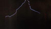
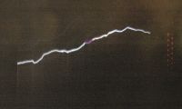
OK here is my fabulous "improvement". It is so simple it only took me 4 or 5 hours and a few blown high power ultrafast diodes and TVS's. In the end I settled for this. Only 4 components, two of which are red LED's.
Simply, it reads the polarity of a spark. The led closest to the spark is negative ie the spark from the toroid on the left is a negative leader.
They then alternate polarity far further than one can see as a spark.
Lots of interesting stuff is going on here now that I have looked at many of then. More in future posts
Guess how I did it. ie what are the two other components.
Peter
Tesladownunder, Wed Sept 20 2006, 12:04PM
OK here is my fabulous "improvement". It is so simple it only took me 4 or 5 hours and a few blown high power ultrafast diodes and TVS's. In the end I settled for this. Only 4 components, two of which are red LED's.
Simply, it reads the polarity of a spark. The led closest to the spark is negative ie the spark from the toroid on the left is a negative leader.
They then alternate polarity far further than one can see as a spark.
Lots of interesting stuff is going on here now that I have looked at many of then. More in future posts

Guess how I did it. ie what are the two other components.
Peter


Re: High speed Tesla spark photos
Terry Fritz, Thu Sept 21 2006, 12:34AM
Hi,
Steve Conner said
The scope could be postitioned in the picture outside the spinning mirror. Probably need another mirror so you can put the scope at a distance so it will be in focus. I guess you would have to run in single shot so 50 images combined would not smear it up. Of course, digital scopes display the data far too late to be useful. There might be some odd way to use the camera hot shoe to trigger the scope on just the right spark too.
I made an LED scope thing once with them but I am not sure they can do say 500kHz. It would be easy to test if anyone has a LM3914 around. That data sheet did not say.
TDU said:
I will "guess" two LEDs a resistor and a MOV. The strike current might be 2000A for a few nS which will kill most TVSs and such. It really helps to keep the device voltage low so the instant power is lower too. A capacitor might also work if one could guess the right value.
Cheers,
Terry
Terry Fritz, Thu Sept 21 2006, 12:34AM
Hi,
Steve Conner said
Is there any way you could get an oscilloscope screen to appear in your streak photo, showing the instantaneous voltage? I can't imagine how you would create a trace that wasn't smeared because of the phosphor persistence of the scope.
The scope could be postitioned in the picture outside the spinning mirror. Probably need another mirror so you can put the scope at a distance so it will be in focus. I guess you would have to run in single shot so 50 images combined would not smear it up. Of course, digital scopes display the data far too late to be useful. There might be some odd way to use the camera hot shoe to trigger the scope on just the right spark too.
Maybe you could make a LED bargraph showing the instantaneous output voltage, and the motion of the mirror would turn it into a scope trace. I don't know if those LM3914 thingies are fast enough to hook up to an antenna.
I made an LED scope thing once with them but I am not sure they can do say 500kHz. It would be easy to test if anyone has a LM3914 around. That data sheet did not say.
TDU said:
Guess how I did it. ie what are the two other components.Cool!
I will "guess" two LEDs a resistor and a MOV. The strike current might be 2000A for a few nS which will kill most TVSs and such. It really helps to keep the device voltage low so the instant power is lower too. A capacitor might also work if one could guess the right value.
Cheers,
Terry
Re: High speed Tesla spark photos
Tesladownunder, Thu Sept 21 2006, 01:11AM
Two LED's and a resistor OK, but not a MOV.
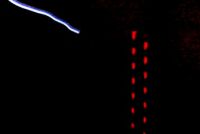
The photos are interesting. Remember a negative strike lights the left LED. From what I have seen they show that the first strike can be positive or negative but there is a lot of structure and chaotic events in the few microseconds either side of a strike. There is often a small streamer hit of opposite polarity just before but both polarities are often seen within the strike. Perhaps much higher frequency oscillation>1Mhz.
Peter
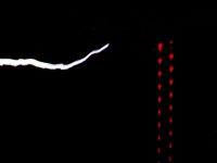
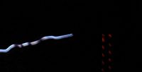

Tesladownunder, Thu Sept 21 2006, 01:11AM
Terry Fritz wrote ...
... will "guess" two LEDs a resistor and a MOV. The strike current might be 2000A for a few nS which will kill most TVSs and such. It really helps to keep the device voltage low so the instant power is lower too. A capacitor might also work if one could guess the right value.
I was surprised that fast devices fared worse than LED's. Interestingly only my two red LED's have survived and I am really pushing them very hard. Blue and green worked on my lower power ignition coil only but not on the TC even when treated very gently.... will "guess" two LEDs a resistor and a MOV. The strike current might be 2000A for a few nS which will kill most TVSs and such. It really helps to keep the device voltage low so the instant power is lower too. A capacitor might also work if one could guess the right value.
Two LED's and a resistor OK, but not a MOV.
The photos are interesting. Remember a negative strike lights the left LED. From what I have seen they show that the first strike can be positive or negative but there is a lot of structure and chaotic events in the few microseconds either side of a strike. There is often a small streamer hit of opposite polarity just before but both polarities are often seen within the strike. Perhaps much higher frequency oscillation>1Mhz.
Peter


Re: High speed Tesla spark photos
Terry Fritz, Thu Sept 21 2006, 01:58AM
Hi,
One of my high speed pictures caught something unusual. It was just a normal power arc:

But when I pumped up the brightness and contrast to see the lead up pulses, I see there is like a "cloud" of ions or something after the strike (time is increasing upward). 1MB picture since I did not want to loose detail.

There is a little air streamer super imposed on the lower image while the shutter was open. Note the cloud that almost looks like smoke from the main strike. They are fairly bright and fuzzy so I assume some type of ionized cloud or something.
A similar strike does not show the effect:

A blank frame seems like the situation is clear of abnormalities:

So I think the cloud or whatever was real.
Cheers,
Terry
Terry Fritz, Thu Sept 21 2006, 01:58AM
Hi,
One of my high speed pictures caught something unusual. It was just a normal power arc:

But when I pumped up the brightness and contrast to see the lead up pulses, I see there is like a "cloud" of ions or something after the strike (time is increasing upward). 1MB picture since I did not want to loose detail.

There is a little air streamer super imposed on the lower image while the shutter was open. Note the cloud that almost looks like smoke from the main strike. They are fairly bright and fuzzy so I assume some type of ionized cloud or something.
A similar strike does not show the effect:

A blank frame seems like the situation is clear of abnormalities:

So I think the cloud or whatever was real.
Cheers,
Terry
Re: High speed Tesla spark photos
Tesladownunder, Thu Sept 21 2006, 02:43AM

Tesladownunder, Thu Sept 21 2006, 02:43AM
Terry Fritz wrote ...
One of my high speed pictures caught something unusual. ... I see there is like a "cloud" of ions or something .... so I assume some type of ionized cloud or something....
So I think the cloud or whatever was real.
..Who do you call One of my high speed pictures caught something unusual. ... I see there is like a "cloud" of ions or something .... so I assume some type of ionized cloud or something....
So I think the cloud or whatever was real.

Re: High speed Tesla spark photos
Terry Fritz, Thu Sept 21 2006, 09:40PM
Hi Peter,
I made one too but I have not tested it with the camera yet. Mine uses a CT, 2 resistors, and the two LEDs:

The CT is just in the secondary base lead:

I just made a little wood block to hold the LEDs:


My coil hits about 6 amps peak on the secondary which puts about 32mA into the LED with this circuit.
My camera is undergoing the table saw, glue, wood, clamps and black paint now for REV-2 Once the paint is dry and it is back together, I will have a much wider veiwing area. I gave up on adding another mirror since the physics did not work out. So I just fixed all the issues with the one I had. Wonder if I'll still see the ghosts
Cheers,
Terry
Terry Fritz, Thu Sept 21 2006, 09:40PM
Hi Peter,
Simply, it reads the polarity of a spark. The led closest to the spark is negative ie the spark from the toroid on the left is a negative leader.
They then alternate polarity far further than one can see as a spark.
I made one too but I have not tested it with the camera yet. Mine uses a CT, 2 resistors, and the two LEDs:

The CT is just in the secondary base lead:

I just made a little wood block to hold the LEDs:


My coil hits about 6 amps peak on the secondary which puts about 32mA into the LED with this circuit.
My camera is undergoing the table saw, glue, wood, clamps and black paint now for REV-2
 Once the paint is dry and it is back together, I will have a much wider veiwing area. I gave up on adding another mirror since the physics did not work out. So I just fixed all the issues with the one I had. Wonder if I'll still see the ghosts
Cheers,
Terry
Re: High speed Tesla spark photos
Tesladownunder, Fri Sept 22 2006, 12:50AM
The circuit diagram mystery of the polarity detectng LED's is very simple. Just two 10 ohm 1 watt resistors and the two red LED's.
One of the resistors is connected to the ground electrode on one end and the spark hits the other end of the resistor. So if 2000 A passes then a 10 ohm non inductive resistor should develop 20,000 V across it, which is enough to spark right across it on the outside. I have seen this happen with higher value resistors.
The other 10 ohm resistor is in series with the two LED's which are in parallel but of opposite polarity (=anti-parallel). This then goes across the first 10 ohm resistor. So why should this work when theoretically the LED's should be receiving half of the 2000A. ie 1000A in each LED in each cycle. We know that we can push current limits in an IGBT to perhaps 100 times the continuous current rating, but this is 50,000 times overload (1000A vs 20mA).
So what is happenning? I suspect that the actual arc current is a lot lower. Added to that is the higher inductance of the loop made by the LED and secondary 10 ohm resistor compared with the main 10 ohm one alone.
I knew I wouldn't be able to work out real performance with out some trial and error so that's how I came up with this. I did try the resistors separately to see if they would flash over due to inductance issues but they were OK. The values seem bizarre but work. Note that you can't run the LED's off DC without putting about 0.4A through the 10 ohm resistor (=4W) and burning it up rapidly.
It really is bright considering the fact that it is only pulsing in several microsecond pulses for brief periods. I think something is different about the red LED's other than just the lower forward voltage (compared with the blue/green ones) that allows them to survive.
What is also interesting is to use spark gap arrestors which also show the really fast stuff without burning out. Interestingly, focally they are brighter than the arc itself and a bit more of a point source. In the end I used the LED's but certainly worth thinking of the arrestors for > 1MHz fast stuff if you could find a way to rectify them. A knowledge of microwave type design and components is something I don't have.
Peter

Re: High speed Tesla spark photos
Terry Fritz, Fri Sept 22 2006, 03:19AM
Hi Peter,
I made a different version.


Mine works off secondary base current. Sort of 90 degrees out of phase, but easy if you know what's going on ) It seems to give very sharp points of light to the streak cam. Maybe good or bad depending on how one looks at it. Positive is closest to the spark per your standard
Mine looks like this to cam V-2.0.

One will notice the "1/4 wave" leader there ))
))
StreakCam V-2.0 is "here":


The mirror was spinning at 7500 RPM in those photos but "cheap cam" made it look "still"... I have been pushing higher RPMs now to separate the lead up leaders... If anything gives way, I get to go buy a "new" camera )
)
I think the polarity indicator needs to be moved to the top terminal point. I think we both can do that...
Cheers,
Terry
UPDATE:
This high-speed streak cam photo pretty much sums it all up!

Cheers,
Terry
Terry Fritz, Fri Sept 22 2006, 03:19AM
Hi Peter,
I made a different version.


Mine works off secondary base current. Sort of 90 degrees out of phase, but easy if you know what's going on
 ) It seems to give very sharp points of light to the streak cam. Maybe good or bad depending on how one looks at it. Positive is closest to the spark per your standard
Mine looks like this to cam V-2.0.

One will notice the "1/4 wave" leader there
 ))
))StreakCam V-2.0 is "here":


The mirror was spinning at 7500 RPM in those photos but "cheap cam" made it look "still"... I have been pushing higher RPMs now to separate the lead up leaders... If anything gives way, I get to go buy a "new" camera
 )
)I think the polarity indicator needs to be moved to the top terminal point. I think we both can do that...
Cheers,
Terry
UPDATE:
This high-speed streak cam photo pretty much sums it all up!

Cheers,
Terry
Re: High speed Tesla spark photos
Steve Conner, Fri Sept 22 2006, 09:12AM
Wow! I never would have thought that secondary base current would spike during a strike. The secondary is a big inductor after all: it shouldn't be possible to force sudden sharp pulses of current through it.
By this line of reasoning, I always assumed that the high currents in a ground arc were supplied from the capacitance between the toroid and grounded surfaces in the room, and therefore they would return through the main ground connection, not the secondary base. I guess the secondary has self-capacitance too though, that looks roughly like a capacitor between the toroid and the secondary base connection. So that could explain it.
Could you try putting your indicator CT in the wire that grounds the whole apparatus to whatever earth you use? (and maybe try the strike target wire too for comparison) It would be interesting to see the relative magnitudes and timings of the secondary base spike and the "surroundings current" spike.
Re: High speed Tesla spark photos
Tesladownunder, Fri Sept 22 2006, 03:38PM
BTW the LED nearest the spark has the cathode end towards the spark (the big internal support) so I figured the toroid is at a negative potential.
...but I haven't finished yet. I am about to glue a bigger mirror with which I will be able to catch a full width spark with full lens aperture and screen resolution. I should see more of the streamers connecting as you do. Hopefully some shots tomorrow if I can get it set up and it doesn't rain again like today.
Photo shows a negative strike with a brief initial flash of positive but it remains negative for a full cycle after that. Hard to explain. (Time is down, strike is followed by a ring down at about 100kHz.)
Peter
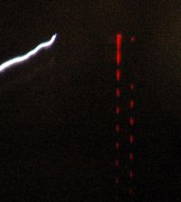
Tesladownunder, Fri Sept 22 2006, 03:38PM
Terry Fritz wrote ...
Mine works off secondary base current. Sort of 90 degrees out of phase, but easy if you know what's going on ) It seems to give very sharp points of light to the streak cam. Maybe good or bad depending on how one looks at it. Positive is closest to the spark per your standard
The LEDs do give a sharp point although my pics were out of focus. Mine really shows ring down well with perhaps 24 LED flashes and yours shows ring up well with several LED flashes. I have pondered this and I suspect that mine is a very hot close spark running 10 inches when it is able to jump 4 feet. It certainly looks more like a Jacobs ladder when that close. Mine works off secondary base current. Sort of 90 degrees out of phase, but easy if you know what's going on
 ) It seems to give very sharp points of light to the streak cam. Maybe good or bad depending on how one looks at it. Positive is closest to the spark per your standard
BTW the LED nearest the spark has the cathode end towards the spark (the big internal support) so I figured the toroid is at a negative potential.
Terry Fritz wrote ...
I think the polarity indicator needs to be moved to the top terminal point. I think we both can do that...
I think I can find a crocodile clip somewhere...I think the polarity indicator needs to be moved to the top terminal point. I think we both can do that...
Terry Fritz wrote ...
This high-speed streak cam photo pretty much sums it all up!
It's a great photo and I vote it for number one Tesla streak camera photo of the week.This high-speed streak cam photo pretty much sums it all up!
...but I haven't finished yet. I am about to glue a bigger mirror with which I will be able to catch a full width spark with full lens aperture and screen resolution. I should see more of the streamers connecting as you do. Hopefully some shots tomorrow if I can get it set up and it doesn't rain again like today.
Photo shows a negative strike with a brief initial flash of positive but it remains negative for a full cycle after that. Hard to explain. (Time is down, strike is followed by a ring down at about 100kHz.)
Peter

Re: High speed Tesla spark photos
Terry Fritz, Sat Sept 23 2006, 08:43PM
Steve Conner Wrote:
Have to get the scope in there too look around. Ground strikes apparently discharge the top terminal in 10's of nS so current probes don't show it we'll.

The arc actually continues on until the energy stored as current in the secondary is also grounded out which takes far longer (but at far lower current) and is probably the "wash out" we see in the main arc. Of course there are all kinds of space charges and such going on too... One could probably use a larger number of Peter's probes to get a better idea. The fast discharge oscilates too with the ground leads and all so maybe that is some of the fast reverse polarity Peter sees. My probe reacts too slow for such things.
I am looking into the LM3914 thing too...
Peter Wrote:
"I" have never seen the ring "down" "after" the strike... Apparently "you" have never seen the ring "up" "before" the strike... I suspect one of us has something backwards or upside down I'll try to check mine out...
I will also try to get you indicator going here.
Cheers,
Terry
UPDATE:
I built Peter's LED thing and it works fine! I put the LEDs in anti-parallel where I think he put them in series. I also wonder if the 10 ohm resistor in series with the LEDs should be a higher value since the LEDs seem "too" bright.
So I set it up like this:

Time is from bottom to top (I checked it again). The files are big to presever detail (~400k).
My base current sensor is on the ground strike point to the right while Peter's LED thing is on the arc wire to the left. The distance is 22 inches. I also uped the speed of the mirrors to 10,000RPM now.
This is a pretty typical arc. Note the well placed breif opposite current indicated on peter's sensor as the arc stikes.

This one shows the leaders:

This one shows that odd 2.5uS second harmonic or whatever. This leader just barely began to strike.

This arc has lots of preglow whish may be related to the 2.5uS thing...

Peter's sensor measures a very long current for the strike here:

This one shows the ringup and back down without a strike:

This one has a lot going on:

Another near miss:

My base current sensor records "two" negative pulses here:

Cheers,
Terry
Terry Fritz, Sat Sept 23 2006, 08:43PM
Steve Conner Wrote:
Wow! I never would have thought that secondary base current would spike during a strike. The secondary is a big inductor after all: it shouldn't be possible to force sudden sharp pulses of current through it.
Have to get the scope in there too look around. Ground strikes apparently discharge the top terminal in 10's of nS so current probes don't show it we'll.

The arc actually continues on until the energy stored as current in the secondary is also grounded out which takes far longer (but at far lower current) and is probably the "wash out" we see in the main arc. Of course there are all kinds of space charges and such going on too... One could probably use a larger number of Peter's probes to get a better idea. The fast discharge oscilates too with the ground leads and all so maybe that is some of the fast reverse polarity Peter sees. My probe reacts too slow for such things.
I am looking into the LM3914 thing too...
Peter Wrote:
(Time is down, strike is followed by a ring down at about 100kHz.)
"I" have never seen the ring "down" "after" the strike... Apparently "you" have never seen the ring "up" "before" the strike... I suspect one of us has something backwards or upside down
 I'll try to check mine out...
I will also try to get you indicator going here.
Cheers,
Terry
UPDATE:
I built Peter's LED thing and it works fine! I put the LEDs in anti-parallel where I think he put them in series. I also wonder if the 10 ohm resistor in series with the LEDs should be a higher value since the LEDs seem "too" bright.
So I set it up like this:

Time is from bottom to top (I checked it again). The files are big to presever detail (~400k).
My base current sensor is on the ground strike point to the right while Peter's LED thing is on the arc wire to the left. The distance is 22 inches. I also uped the speed of the mirrors to 10,000RPM now.
This is a pretty typical arc. Note the well placed breif opposite current indicated on peter's sensor as the arc stikes.

This one shows the leaders:

This one shows that odd 2.5uS second harmonic or whatever. This leader just barely began to strike.

This arc has lots of preglow whish may be related to the 2.5uS thing...

Peter's sensor measures a very long current for the strike here:

This one shows the ringup and back down without a strike:

This one has a lot going on:

Another near miss:

My base current sensor records "two" negative pulses here:

Cheers,
Terry
Re: High speed Tesla spark photos
Tesladownunder, Sun Sept 24 2006, 12:51AM
I have a photo with ring down and ring up in the same photo. Your ring up is OK. Streamers ring up and sparks ring down (from TC spark photography 101 )
)
I thought that 10 ohms would be too little but with a true adventuring spirit I kept going down. Perhaps I should try 1 ohm or nothing. I have plenty of LED's. It is all a bit non-intuitive for our usual electronics.
 They are brighter and have a ? faster response by the look than your base current transformer. Also no phasing issues
So back to my progress or lack of it.
My larger mirror was a conventional rear silvered mirror of dubious parentage. I was hoping it wouldn't matter. I was wrong (I think). I can't get my focus to work properly when it is running. If I can't get around that I will need to get a decent first surface mirror that is halfway flat.
Here are the pics . Note that this is is in the USA format with time up and toroid on left.
(oops this one isn't the one that shows my incorrectly wired diodes on the right giving a single pulse only.)
The first shot shows a 25inch spark with lots of ringdown on the LED's but none visible. The lack of visibility may be partly due to the poor focus. (I used to be able to see them OK).
Second pic is of streamers connecting. It would be interesting to see how each side (toroid and ground) would respond in this case. They may not be identical.
Peter
Update:
I have tried a new focusing technique which helped but didnt fix the focus issue so there is likely a residual mirror effect. I will consider a repair with a better mirror.
Nevertheless I got better shots now I have wired my LEDs better. The LED issue is even more interesting and I will post interesting stuff when I get a reply to the LED post.
I have got some streamers ring up shots and spark ringdown shots, but never the two together.
Will post more pics with next reply or check the website.
I've taken 500 photos in the last two days with a combination of the Tesla streak cam shots, new improved vortex generator and the LED experiments. Takes time to collate them all.


Tesladownunder, Sun Sept 24 2006, 12:51AM
Terry Fritz wrote ...
"I" have never seen the ring "down" "after" the strike... Apparently "you" have never seen the ring "up" "before" the strike... I suspect one of us has something backwards or upside down
Terry, try reducing your spark distance to 6 inches and I bet you will see the ring down. There is less streamer action at that distance though as they connect a lot faster."I" have never seen the ring "down" "after" the strike... Apparently "you" have never seen the ring "up" "before" the strike... I suspect one of us has something backwards or upside down

I have a photo with ring down and ring up in the same photo. Your ring up is OK. Streamers ring up and sparks ring down (from TC spark photography 101
 )
) Terry Fritz wrote ...
I built Peter's LED thing and it works fine! I put the LEDs in anti-parallel where I think he put them in series. I also wonder if the 10 ohm resistor in series with the LEDs should be a higher value since the LEDs seem "too" bright.
My LED's are in anti parallel. They work amazingly well. It is quite remarkable to see huge arcs playing around them. What is even more remarkable is that I wired one set in parallel by mistake and they didn't blow. They must avalanche well, at least the red ones. I will start a new thread on the LED topic as I have some other info as well.I built Peter's LED thing and it works fine! I put the LEDs in anti-parallel where I think he put them in series. I also wonder if the 10 ohm resistor in series with the LEDs should be a higher value since the LEDs seem "too" bright.
I thought that 10 ohms would be too little but with a true adventuring spirit I kept going down. Perhaps I should try 1 ohm or nothing. I have plenty of LED's. It is all a bit non-intuitive for our usual electronics.
Terry Fritz wrote ...
My base current sensor is on the ground strike point to the right while Peter's LED thing is on the arc wire to the left. The distance is 22 inches. I also uped the speed of the mirrors to 10,000RPM now.
You are getting great results. Why don't you use two of my LED sensor things My base current sensor is on the ground strike point to the right while Peter's LED thing is on the arc wire to the left. The distance is 22 inches. I also uped the speed of the mirrors to 10,000RPM now.
 They are brighter and have a ? faster response by the look than your base current transformer. Also no phasing issues
So back to my progress or lack of it.
My larger mirror was a conventional rear silvered mirror of dubious parentage. I was hoping it wouldn't matter. I was wrong (I think). I can't get my focus to work properly when it is running. If I can't get around that I will need to get a decent first surface mirror that is halfway flat.
Here are the pics . Note that this is is in the USA format with time up and toroid on left.
(oops this one isn't the one that shows my incorrectly wired diodes on the right giving a single pulse only.)
The first shot shows a 25inch spark with lots of ringdown on the LED's but none visible. The lack of visibility may be partly due to the poor focus. (I used to be able to see them OK).
Second pic is of streamers connecting. It would be interesting to see how each side (toroid and ground) would respond in this case. They may not be identical.
Peter
Update:
I have tried a new focusing technique which helped but didnt fix the focus issue so there is likely a residual mirror effect. I will consider a repair with a better mirror.
Nevertheless I got better shots now I have wired my LEDs better. The LED issue is even more interesting and I will post interesting stuff when I get a reply to the LED post.
I have got some streamers ring up shots and spark ringdown shots, but never the two together.
Will post more pics with next reply or check the website.
I've taken 500 photos in the last two days with a combination of the Tesla streak cam shots, new improved vortex generator and the LED experiments. Takes time to collate them all.

Re: High speed Tesla spark photos
Terry Fritz, Sun Sept 24 2006, 03:12PM
Peter Wrote:
Oh! OK!! I never understood that before. I see now.
I am working on a 20 segment LM3914 based LED array run from the current transformer. However I need to test the LM3914 first to see if it will work fast enough. I hope I can get one locally to test.
For focus, I have just been measuring the distance and setting the camera's manual focus to that distance. Seems to work fine. You could also set the camera up towards a picture on a wall or something at the same distance.
Cheers,
Terry
Terry Fritz, Sun Sept 24 2006, 03:12PM
Peter Wrote:
Terry, try reducing your spark distance to 6 inches and I bet you will see the ring down.
Oh! OK!! I never understood that before. I see now.
I am working on a 20 segment LM3914 based LED array run from the current transformer. However I need to test the LM3914 first to see if it will work fast enough. I hope I can get one locally to test.
For focus, I have just been measuring the distance and setting the camera's manual focus to that distance. Seems to work fine. You could also set the camera up towards a picture on a wall or something at the same distance.
Cheers,
Terry
Re: High speed Tesla spark photos
Tesladownunder, Sun Sept 24 2006, 03:33PM
Hundreds of photos each a little different.
Back to the Australian standard of time going down and toroid on the left. Did the focus differently but I think the mirror is preventing better results. A bit like the Hubbles predicament after it got launched with a dodgy mirror.
Photo
1 Mirror stationary. LED monitors at both ends and read in the same direction. Cathode (negative) is closest to the spark at the toroid end
2 Streamer with ring up of a number of cycles but fades without a strike.
3 Streamer from toroid plus streamer from the ground (bypassed my LED's)
4 A horizontal spark with ring down, crosses a superimposed diagonal streamer with ring up. You don't get to see ring up and ring down on the same spark.
Check out the new current meter in the LEDs for spark monitoring thread. Should work well. Has 6 orders of magnitude coverage (theoretically).
Peter
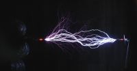


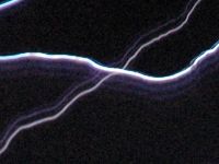
Tesladownunder, Sun Sept 24 2006, 03:33PM
Hundreds of photos each a little different.

Back to the Australian standard of time going down and toroid on the left. Did the focus differently but I think the mirror is preventing better results. A bit like the Hubbles predicament after it got launched with a dodgy mirror.
Photo
1 Mirror stationary. LED monitors at both ends and read in the same direction. Cathode (negative) is closest to the spark at the toroid end
2 Streamer with ring up of a number of cycles but fades without a strike.
3 Streamer from toroid plus streamer from the ground (bypassed my LED's)
4 A horizontal spark with ring down, crosses a superimposed diagonal streamer with ring up. You don't get to see ring up and ring down on the same spark.
Check out the new current meter in the LEDs for spark monitoring thread. Should work well. Has 6 orders of magnitude coverage (theoretically).
Peter


Re: High speed Tesla spark photos
Tesladownunder, Sun Oct 01 2006, 05:17PM
I have been a bit busy with other pursuits such as picking up some big old
discarded physics equipment and attending the Tesla exhibition. A week
without new developments has been a long time in the high speed Tesla
photography field.
I was however able to obtain a new higher quality mirror of 10 x 15 cm which although rear silvered, does not show any distortion visibly when viewed
from a distance. It is well centered but moves a fearsome amount of air and
has some vibration at 3000 RPM (250 VAC) but 2000 RPM (85 VAC)seems
comfortable. It is a big mirror to spin fast but the aluminium supports seem
to hold it firmly without adding too much weight or obstructing the view.
The reduced revs should be countered by the much clearer and wider view.
Still needs to be tested in use though.
Now that my mirror is mounted it does have some distortion not present previously due to bending forces from the support. It remains to be seen how much this affects things.
I have also done some testing on a 7 stage LED meter to get the feel for how
it will work. Now have to make a reverse copy to indicate the opposite
polarity then run things with the new mirror.
Peter
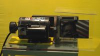
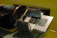


Re: High speed Tesla spark photos
Terry Fritz, Sun Oct 01 2006, 10:21PM
Hi Peter,
Cool!! Looking forward to seeing this new system work!!!
I have not been able to get anything done lately Busy this coming week too... But I'll try...
Since the mirror is always used at an angle and the small distortions don't really hurt this stuff much, I wonder if any cheap old rear silvered mirror would just just fine! Be very interesting to see what your quality mirror shows.
BTW - To followup on what Steve Conner mentioned about ground strikes, I found this blurb I wrote for ScanTesla's Streamer hit modeling:

Cheers,
Terry
Terry Fritz, Sun Oct 01 2006, 10:21PM
Hi Peter,
Cool!! Looking forward to seeing this new system work!!!
I have not been able to get anything done lately
 Busy this coming week too... But I'll try...
Since the mirror is always used at an angle and the small distortions don't really hurt this stuff much, I wonder if any cheap old rear silvered mirror would just just fine! Be very interesting to see what your quality mirror shows.
BTW - To followup on what Steve Conner mentioned about ground strikes, I found this blurb I wrote for ScanTesla's Streamer hit modeling:

Cheers,
Terry
Re: High speed Tesla spark photos
Tesladownunder, Mon Oct 02 2006, 03:26PM
Well, I've taken well over 500 photos today and have whittled them down to 100 for a closer look.
Photo 1 A little mirror aberration giving ghosting due to flex of the mirror in the support giving horizontal displacement. Seemed to get worse during the day so needs a new design with no stress and epoxied in place. Possibly a proper mirror.
Photo 2 A full 2 foot spark with a spark that is 3 pixels wide (1 pixel per microsecond in these shots). This was a daytime shot and in retrospect was probably sharper than the night shots as it was f18 and 1/10 sec. Night shots were f3.5 and longer duration.
Photo 3 I got quite interested since almost all of my photos showed the negative LED firing well, but I guess this was some asymmetry in the LED's as it seems to be just happening today. Makes you wonder though as I was using slow ASRG rates today.
Photo 4 I did try a current meter but I have had problems with it. Possibly overvolting the metal film 1.8 W resistors. Certainly looks like one resistor is open circuit here. They should fire at 0.01, 0.1, 1 and 10 amps respectively but the 1 amp LED is firing too readily. The 100A and above LED's never fired. (but did with a capacitor on a rectified ignition coil setup).
Photo 5 I was intrigued by this streamer shot showing a second and possibly third group of streamers following.
Photo 6 I added a spark arrestor and a disposable camera xenon flash in series with unprotected LED's and got this interesting but blurred streamer shot showing a remarkble 6 streamer groups that the camera and LED's weren't picking up. Seems like there is a another frequency superimposed of perhaps 8-10kHz. I presume that this is the difference between primary and secondary resonances (the "notch"). I am running it a bit out of tune still so that may account for that. It could actually explain a row of negative only ring down sparks as well.
Peter
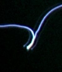
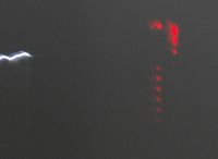
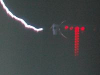
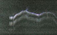
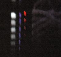


Re: High speed Tesla spark photos
Terry Fritz, Sat Oct 07 2006, 06:43AM
Hi Peter,
At 07:33 PM 10/5/2006, you wrote:
.......
Starting to work on my new "secret weapon" soon too.
 ))))
))))
Terry has made up his own superfast rotating mirror unit (10,000 RPM) and is also getting great results. He is planning a voltmeter/current meter for his unit as below.
.............
Peter
It actually goes to near "50,000 RPM" with the 300A(!) stall current motor being run at "only" 2X voltage :o)) But I only take pictures at around 10,000 RPM. The motor is really scarry at 50,000 =:O I ran it up there once with the mirrors and all (NOT the camera!) and it was sort of like a jet engine!! But it held together fine!! I may have bent the motor shaft "just a little" pressing the mirror block on it at 4000 pounds and tapping with a hammer... Like the Egg of Columbus thing... It just "finds" its center highest "Q" of rotating mass...
I removed the safety Lexan shield now since it "got in the way". The camera lens is now very close to the spinning mirror:
 (mirror "was" spinning there, but "cheap cam" is "fast" and froze the image)...

If it blows the old camera lens out, I could get one of these )
)

I have not done much for a long time now..., but I did manage to order parts and started work on the streak camera "oscilloscope" today )) Here is what I have so far:

The "Light Bar" has 24 high brightness LEDs. Three green ones define the top, middle, and bottom of the scale. 20 red LEDs fill in the bare graph scale on the +-5 volts at 0.5 volt increments. There is an extra green LED which will have the 100.0kHz calibration scale function. The holes were drilled in 0.75 inch angle aluminium to 0.192 inches and the LEDs are "pounded" in with a bit of 1/4 inch tubing "very tight". The LED spacing is 0.375 inch. The front was sprayed with matt black. The assembly is 9.75 inches long.
A proto board will hold the LM319s (all of them "cost less" than just "one" of the green LEDs!), the +-5V regulators, and the LMC555 circuit. I need to figure out how to do the voltage divider array and the LED drop resistors. That will be easily "creative" )
)
I have two 9V batteries for +- 9V and 4 AA batteries to drive the LEDs. There is a block for the +-5V input and a power switch. I will sandwich it between copper FR4 board material cut to suit for HV/RF shielding. Running the circuit should not be any problem at all considering what I have done before )
)


It should be able to sit on top of the toroid will a little aluminum foil field control stuff. Almost any CT can go into it. I have TI ICs which should go to 1MHz, and if they blow, they are $0.20 each... I will sprinkle in caps and 24V TVSs as needed... Should be cool!!!
Cheers,
Terry
Terry Fritz, Sat Oct 07 2006, 06:43AM
Hi Peter,
At 07:33 PM 10/5/2006, you wrote:
.......
Starting to work on my new "secret weapon" soon too.
 ))))
))))Terry has made up his own superfast rotating mirror unit (10,000 RPM) and is also getting great results. He is planning a voltmeter/current meter for his unit as below.
.............
Peter
It actually goes to near "50,000 RPM" with the 300A(!) stall current motor being run at "only" 2X voltage :o)) But I only take pictures at around 10,000 RPM. The motor is really scarry at 50,000 =:O I ran it up there once with the mirrors and all (NOT the camera!) and it was sort of like a jet engine!! But it held together fine!! I may have bent the motor shaft "just a little" pressing the mirror block on it at 4000 pounds and tapping with a hammer... Like the Egg of Columbus thing... It just "finds" its center highest "Q" of rotating mass...
I removed the safety Lexan shield now since it "got in the way". The camera lens is now very close to the spinning mirror:
 (mirror "was" spinning there, but "cheap cam" is "fast" and froze the image)...
If it blows the old camera lens out, I could get one of these
 )
)
I have not done much for a long time now..., but I did manage to order parts and started work on the streak camera "oscilloscope" today
 )) Here is what I have so far:
The "Light Bar" has 24 high brightness LEDs. Three green ones define the top, middle, and bottom of the scale. 20 red LEDs fill in the bare graph scale on the +-5 volts at 0.5 volt increments. There is an extra green LED which will have the 100.0kHz calibration scale function. The holes were drilled in 0.75 inch angle aluminium to 0.192 inches and the LEDs are "pounded" in with a bit of 1/4 inch tubing "very tight". The LED spacing is 0.375 inch. The front was sprayed with matt black. The assembly is 9.75 inches long.
A proto board will hold the LM319s (all of them "cost less" than just "one" of the green LEDs!), the +-5V regulators, and the LMC555 circuit. I need to figure out how to do the voltage divider array and the LED drop resistors. That will be easily "creative"
 )
)I have two 9V batteries for +- 9V and 4 AA batteries to drive the LEDs. There is a block for the +-5V input and a power switch. I will sandwich it between copper FR4 board material cut to suit for HV/RF shielding. Running the circuit should not be any problem at all considering what I have done before
 )
)


It should be able to sit on top of the toroid will a little aluminum foil field control stuff. Almost any CT can go into it. I have TI ICs which should go to 1MHz, and if they blow, they are $0.20 each... I will sprinkle in caps and 24V TVSs as needed... Should be cool!!!
Cheers,
Terry
Re: High speed Tesla spark photos
Tesladownunder, Sat Oct 07 2006, 07:52AM
Sorry my secret weapon is even more secret than that But it will have other applications as well. It is really fairly easy in concept anyway but thats as far as I have got so far.
Some more pics:
Photo 1 shows a streamer branch with only alternate streamers progressing from left to right after the branch. This suggests some polarity effect at the time e.g. negative goes to the upright branch and positive continues on.
Photo 2 shows detail of a streamer that connects during the time when the harmonic is resulting in low voltages, hence the current is low and the spark is not strong. As the voltage picks up, there is enough energy for a second strike. The left LED's are not functioning properly but do indicate the first group of firings then a gap and then a second lot starting. I also have the spark arrestor running here which is the blue streak between the LED's and the spark.
Photo 3 A busy photo with lots of 3 foot sparks mainly to show one of the 1/8W LED shunt resistors burning up. Photos have better focus on these distant photos.
Photo 4 Another busy photo showing the ringdown better. I have spark arrestors on both ends and on the right antiparallel LED's shunted by antiparallel 3A schottkey's. The LED's still light but the layout is not ideal for nanosecond stuff (I can say that because I have no knowedge at all ).
).
Peter
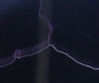

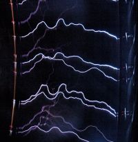
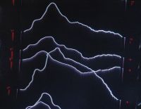
Tesladownunder, Sat Oct 07 2006, 07:52AM
Sorry my secret weapon is even more secret than that
 But it will have other applications as well. It is really fairly easy in concept anyway but thats as far as I have got so far.
Some more pics:
Photo 1 shows a streamer branch with only alternate streamers progressing from left to right after the branch. This suggests some polarity effect at the time e.g. negative goes to the upright branch and positive continues on.
Photo 2 shows detail of a streamer that connects during the time when the harmonic is resulting in low voltages, hence the current is low and the spark is not strong. As the voltage picks up, there is enough energy for a second strike. The left LED's are not functioning properly but do indicate the first group of firings then a gap and then a second lot starting. I also have the spark arrestor running here which is the blue streak between the LED's and the spark.
Photo 3 A busy photo with lots of 3 foot sparks mainly to show one of the 1/8W LED shunt resistors burning up. Photos have better focus on these distant photos.
Photo 4 Another busy photo showing the ringdown better. I have spark arrestors on both ends and on the right antiparallel LED's shunted by antiparallel 3A schottkey's. The LED's still light but the layout is not ideal for nanosecond stuff (I can say that because I have no knowedge at all
 ).
).Peter


Re: High speed Tesla spark photos
Terry Fritz, Sun Oct 08 2006, 04:04AM
Cool pictures! I like #3
I got the streak camera oscilloscope mostly wired today:

It works perfectly and goes to 1MHz. I still have not gotten any of the calibration wired, but the bar graph functions work fine. It might need a little tweaking like the green grid LEDs might be too bright but that is easy to fix if needed.
Cheers,
Terry
UPDATE:
I got the scope all wired and put together and got the first pictures in:

Here it is on top of the toroid ready to go:

Sorry, these are big like 1+Meg pictures but I did not want to loose detail.
First is the scope and all through the camera at 1/400s shutter speed. Each LED is 1/2 amp and time is from bottom to top. The calibration markers are 100kHz and positive is to the right: The four sided mirror is at ~10,000 RPM.

This picture was at 1/40s shutter and the grid lines over lap badly. But the picture is cool in that you can see the ring up and sort of a current decay after the main strike. There is a leader above it that was caught too. If you look close you can easily see the 200kHz 2nd harmonic that Peter has reported and its leader just before the main strike.:

Next I uped the shutter speed to 1/400 sec to get rid of the overlap. This picture had one overlap but it is pretty clear anyway. The streamer is negative and has a 2 Fo harmonic just before the strike and then there is a positive current after the main strike of 1 amp that lasts for about 7.5uS

The last picture is just a leader with some odd details if you look close:

I need to do that following:
1. Dim the grid LEDs so they are not so bright. They cause a little ambient light wash now.
2. Wire the grid and Cal LEDs to only turn on only while the current is >0.5 amp (only during a current event). That will eliminate the overlap problem and allow a far higher chance of getting good shots (like 1/20s shutter speed).
3. Make a little scaling control so that I can increase and decrease the sensitivity. The scope goes to +-5 amps now but it should probably be 2X to 4X that for leaders. Strikes are probably so powerful and fast I will never really catch them properly.
4. "Fiddle" witht things to get the pictures a bit better.
Cheers,
Terry
UPDATE:
All four items above have been fixed now Should be good to go tomorrow morning!
Cheers,
Terry
Terry Fritz, Sun Oct 08 2006, 04:04AM
Cool pictures! I like #3

I got the streak camera oscilloscope mostly wired today:

It works perfectly and goes to 1MHz. I still have not gotten any of the calibration wired, but the bar graph functions work fine. It might need a little tweaking like the green grid LEDs might be too bright but that is easy to fix if needed.
Cheers,
Terry
UPDATE:
I got the scope all wired and put together and got the first pictures in:

Here it is on top of the toroid ready to go:

Sorry, these are big like 1+Meg pictures but I did not want to loose detail.
First is the scope and all through the camera at 1/400s shutter speed. Each LED is 1/2 amp and time is from bottom to top. The calibration markers are 100kHz and positive is to the right: The four sided mirror is at ~10,000 RPM.

This picture was at 1/40s shutter and the grid lines over lap badly. But the picture is cool in that you can see the ring up and sort of a current decay after the main strike. There is a leader above it that was caught too. If you look close you can easily see the 200kHz 2nd harmonic that Peter has reported and its leader just before the main strike.:

Next I uped the shutter speed to 1/400 sec to get rid of the overlap. This picture had one overlap but it is pretty clear anyway. The streamer is negative and has a 2 Fo harmonic just before the strike and then there is a positive current after the main strike of 1 amp that lasts for about 7.5uS

The last picture is just a leader with some odd details if you look close:

I need to do that following:
1. Dim the grid LEDs so they are not so bright. They cause a little ambient light wash now.
2. Wire the grid and Cal LEDs to only turn on only while the current is >0.5 amp (only during a current event). That will eliminate the overlap problem and allow a far higher chance of getting good shots (like 1/20s shutter speed).
3. Make a little scaling control so that I can increase and decrease the sensitivity. The scope goes to +-5 amps now but it should probably be 2X to 4X that for leaders. Strikes are probably so powerful and fast I will never really catch them properly.
4. "Fiddle" witht things to get the pictures a bit better.
Cheers,
Terry
UPDATE:
All four items above have been fixed now
 Should be good to go tomorrow morning!
Cheers,
Terry
Re: High speed Tesla spark photos
Tesladownunder, Mon Oct 09 2006, 12:35AM
Looking forward to your results.
Nothing really new here, just blowing LEDs. Added some information about partial failure in the LED's polarity thread.
I got better results using a groundplane around all the LEDs and resistors so there was little crosstalk/interference and the LED's were lighting nicely in proportion to the decades increments. So that is a start.
I guess dumbing down the spark current to a microsecond event rather than a multi nanosecond one would be kinder to the LED's so I might have to add an RLC filter. Just found some feedthrough caps that I got off eBay for goodness knows why a year or so ago so might be able to experiment with this. I hadn't actually blown my TVS and these might respond at that level or failing that a long string of Schottkeys.
I also think a Xenon flash tube should be the best indicator for very small currents but still be able to accept large ones. The output might be able to be tightened with a cylindrical lens.
Peter
Re: High speed Tesla spark photos
Terry Fritz, Mon Oct 09 2006, 05:56PM
Hi All,
My new streak camera scope is working pretty good now! So I picked a few real cool pictures to share.
This is the setup:

The LED bar graph goes from -2.5A to +2.5A in 0.25A increments. Center is ground and there is a 100kHz maker on the far right. It is directly measuring the current to the arc breakout rod. There are green LEDs at each end for a reference. Time is from the bottom toward the top.
Here is a typical steamer buildup and strike:

There is a 1/2 amp positive leader that goes about 1/4 the distance at 0.5A. On the next positive 1/2 cycle the negative leader goes 1/2 the distance at 0.75 amps. The next positive 1/2 cycle 1.75A leader just falls short of connecting (note the corona off the ground point). The next negative leader connects and discharges the system (a super fast thing the scope cannot report accurately).
Here are two superimposed images showing both positive (bottom) and negative (top) strikes.

I note that negative strikes seem to be brighter in general than positive ones.
Here is a set of three leaders just to the air that never connected:

They seem to be about 0.5A to 0.75A peak. The branching here seems like it draws more current than just a single leader.
Here is a negative leader (top) that connected but never "caught on fire" I guess.

The next positive leader (probably) quickly strikes hard.
Wild stuff!!!
FYI - The mirror speed was 10,000 RPM. At 15,000 RPM the vibration causes the lense to loose focus. I will try to add some hysteresis to the scope display next so it stays on instead of winks out at every zero current crossing. However, these were taken at 1/20s and almost 50% of the pictures are now "good ones"!! Overlaps and total misses are about even now. I still have some problems picking up shadows and glare at times. I think I'll tweak the current up to 0.1A/div too...
Cheers,
Terry
Terry Fritz, Mon Oct 09 2006, 05:56PM
Hi All,
My new streak camera scope is working pretty good now! So I picked a few real cool pictures to share.
This is the setup:

The LED bar graph goes from -2.5A to +2.5A in 0.25A increments. Center is ground and there is a 100kHz maker on the far right. It is directly measuring the current to the arc breakout rod. There are green LEDs at each end for a reference. Time is from the bottom toward the top.
Here is a typical steamer buildup and strike:

There is a 1/2 amp positive leader that goes about 1/4 the distance at 0.5A. On the next positive 1/2 cycle the negative leader goes 1/2 the distance at 0.75 amps. The next positive 1/2 cycle 1.75A leader just falls short of connecting (note the corona off the ground point). The next negative leader connects and discharges the system (a super fast thing the scope cannot report accurately).
Here are two superimposed images showing both positive (bottom) and negative (top) strikes.

I note that negative strikes seem to be brighter in general than positive ones.
Here is a set of three leaders just to the air that never connected:

They seem to be about 0.5A to 0.75A peak. The branching here seems like it draws more current than just a single leader.
Here is a negative leader (top) that connected but never "caught on fire" I guess.

The next positive leader (probably) quickly strikes hard.
Wild stuff!!!
FYI - The mirror speed was 10,000 RPM. At 15,000 RPM the vibration causes the lense to loose focus. I will try to add some hysteresis to the scope display next so it stays on instead of winks out at every zero current crossing. However, these were taken at 1/20s and almost 50% of the pictures are now "good ones"!! Overlaps and total misses are about even now. I still have some problems picking up shadows and glare at times. I think I'll tweak the current up to 0.1A/div too...
Cheers,
Terry
Re: High speed Tesla spark photos
Tesladownunder, Mon Oct 09 2006, 06:52PM
Great shots Terry. I see you have a few hot pixels that I don't recall before. You're not shaking your camera to bits are you
I have to post just so you can post again before 48h.
Work has taken a 17h chunk out of my day so no progress here.
Things for you to do - pulls pencil out. Hmmm...
1 Set your sensitivity for maximum and see all the rest of what is happening , not just the bright stuff. You should see ringdown on EVERY strike like on mine.
2 Try a streamer only shot. You might also see the harmonic effect of 10kHz on streamers or something quite different since your coil is quite different. I suspect you might have to bypass a SISG stage or so to fit that in your room.
3 I favour a log response. Is that feasible with your setup?
4 Can you run a 1MHz test frequency passing through your CT to see how sharp your response is? I also notice my strikes are broad compared with the ringdown.
5 Try a really short arc to ground
Cheers
Peter
Tesladownunder, Mon Oct 09 2006, 06:52PM
Great shots Terry. I see you have a few hot pixels that I don't recall before. You're not shaking your camera to bits are you

I have to post just so you can post again before 48h.
Work has taken a 17h chunk out of my day so no progress here.
Things for you to do - pulls pencil out. Hmmm...
1 Set your sensitivity for maximum and see all the rest of what is happening , not just the bright stuff. You should see ringdown on EVERY strike like on mine.
2 Try a streamer only shot. You might also see the harmonic effect of 10kHz on streamers or something quite different since your coil is quite different. I suspect you might have to bypass a SISG stage or so to fit that in your room.
3 I favour a log response. Is that feasible with your setup?
4 Can you run a 1MHz test frequency passing through your CT to see how sharp your response is? I also notice my strikes are broad compared with the ringdown.
5 Try a really short arc to ground
Cheers
Peter
Re: High speed Tesla spark photos
Terry Fritz, Mon Oct 09 2006, 10:00PM
Hi Peter,
The dark enhancment was done differently. But it really is a 10,000RPM ultrasonic paint shaker, so camera damage is a possibility. But the camera is pretty old and I can live if I have to buy a new one
I just keep updating my old post like I did before
As to your points:
1. I am now at 0.1A/div and I can now see follow up oscillations (scope but camera too dim) right were they should be.
2. This coil does not do well in one shot mode. The streamers are really wimpy. It also has high coupling so the ringup is in only a few cycles.
3. I would have to find a whole new "log" set of scale resistors. Prolly not gonna happen soon since I like linear
4. It goes to 1MHz and then starts to roll off. Pretty predictable...
5. I will try to remember.
Here is on really great shot!!!

It is NOT super imposed! It must have hit just at the peak in the charging cycle and the coil was able to pump out three arcs in 60uS! Each red LED is 0.1A with positive to the right. The markers are 10uS. I don't know what it all means
If anyone is really board:

Pictures with an "a" are enhanced since they showed "something". I have not had time to really look through them.
Cheers,
Terry
Terry Fritz, Mon Oct 09 2006, 10:00PM
Hi Peter,
Great shots Terry. I see you have a few hot pixels that I don't recall before. You're not shaking your camera to bits are you
The dark enhancment was done differently. But it really is a 10,000RPM ultrasonic paint shaker, so camera damage is a possibility. But the camera is pretty old and I can live if I have to buy a new one

I have to post just so you can post again before 48h.
I just keep updating my old post like I did before

As to your points:
1. I am now at 0.1A/div and I can now see follow up oscillations (scope but camera too dim) right were they should be.
2. This coil does not do well in one shot mode. The streamers are really wimpy. It also has high coupling so the ringup is in only a few cycles.
3. I would have to find a whole new "log" set of scale resistors. Prolly not gonna happen soon since I like linear

4. It goes to 1MHz and then starts to roll off. Pretty predictable...
5. I will try to remember.
Here is on really great shot!!!

It is NOT super imposed! It must have hit just at the peak in the charging cycle and the coil was able to pump out three arcs in 60uS!
 Each red LED is 0.1A with positive to the right. The markers are 10uS. I don't know what it all means
If anyone is really board:

Pictures with an "a" are enhanced since they showed "something". I have not had time to really look through them.
Cheers,
Terry
Re: High speed Tesla spark photos
Tesladownunder, Tue Oct 10 2006, 12:34AM

I wonder about the frequency response of your unit. Brief events are giving pyramids rather than lines. I suspect you have less than 1Mhz bandwidth. Turn on maybe but turn off? The reason I say that is the largest spike/pyramid to the right has a small reading to the left at the same time.
Peter
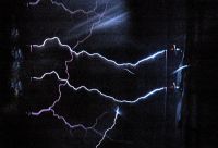
Tesladownunder, Tue Oct 10 2006, 12:34AM
Terry Fritz wrote ...
.... But it really is a 10,000RPM ultrasonic paint shaker, ..
Ultrasonic only for us over 50's. While driving a speaker with up to 100W via a frequency generator for my cornstarch stuff two days ago, my hearing frequency cut out was about 12 kHz, my 16yo was perhaps 17kHz and 14yo 19kHz..... But it really is a 10,000RPM ultrasonic paint shaker, ..
Terry Fritz wrote ...
1. I am now at 0.1A/div and I can now see follow up oscillations (scope but camera too dim) right were they should be.
Nice, can you go lower easily?1. I am now at 0.1A/div and I can now see follow up oscillations (scope but camera too dim) right were they should be.
Terry Fritz wrote ...
2. This coil does not do well in one shot mode. The streamers are really wimpy. It also has high coupling so the ringup is in only a few cycles.
See my 4 foot streamer below 2. This coil does not do well in one shot mode. The streamers are really wimpy. It also has high coupling so the ringup is in only a few cycles.

Terry Fritz wrote ...
4. It goes to 1MHz and then starts to roll off. Pretty predictable...
Is that measured or predicted?4. It goes to 1MHz and then starts to roll off. Pretty predictable...
I wonder about the frequency response of your unit. Brief events are giving pyramids rather than lines. I suspect you have less than 1Mhz bandwidth. Turn on maybe but turn off? The reason I say that is the largest spike/pyramid to the right has a small reading to the left at the same time.
Terry Fritz wrote ...
It is NOT super imposed! It must have hit just at the peak in the charging cycle and the coil was able to pump out three arcs in 60uS!
Are you really sure. I see lots of coincidences and the spark channel can remain hot and give similar shaped sparks for a while. If it was dependant on charging cycle we would see that happen all the time.It is NOT super imposed! It must have hit just at the peak in the charging cycle and the coil was able to pump out three arcs in 60uS!
Peter

Re: High speed Tesla spark photos
Terry Fritz, Tue Oct 10 2006, 03:01AM
Hi Peter,
The scope can go to very low current. The bar graph scale is +-5V and the CT is 100:1 so it just depends on the load resistor (there must be some limit, but I would have to think about it).
The 1MHz is measured with an HP33120A signal generator and a TEK 3012 scope. I could look further if there is a worry.
See the lower strike in this picture:

The arc caused a positive "spike" to the right.
At 1/20th of a second, it is "possible". The chance of the same mirror alighning is 4^2. The chance of the cal dots alighning is about 20^2. The chance of a streamer hitting just right is say 10^2. This picture shows some bright LEDs but they are bright in the wrong places at the wrong times (time is down here):

So the odds are ~ 1/640000...
This is what the alternative looks like:

Possible.... The picture you have is pretty convincing though...
But this happens a lot:


Those markers just seem to happily alighn far too much (5 times in 64 pictures)....
This is an overlap on the same mirror:

This is what I would normally expect (a "rare" picture):

So it sure seems to me like fast multiple firing. It would be 30uS or 33,000BPS!!! Even the SISG "should not" be able to go that fast... Probably our first big "odd" thing to try and figure out.
I put a ton of these pictures in a printer friendly file at:

Sorry about the 13MB but the pictures are high-res even if I did crop them way down.
UPDATE: I checked the bandwidth of my Streak Scope. Here it is on top of the coil hooked to a signal generator:

Here is a 200kHz +-4.7V square wave:

Here is a 100kHz 20% duty cycle +-4.7V square wave.

Looks perfect!! But I should try to find why the three LEDs on the left are dimmer...
Cheers,
Terry
Terry Fritz, Tue Oct 10 2006, 03:01AM
Hi Peter,
The scope can go to very low current. The bar graph scale is +-5V and the CT is 100:1 so it just depends on the load resistor (there must be some limit, but I would have to think about it).
The 1MHz is measured with an HP33120A signal generator and a TEK 3012 scope. I could look further if there is a worry.
I wonder about the frequency response of your unit. Brief events are giving pyramids rather than lines. I suspect you have less than 1Mhz bandwidth. Turn on maybe but turn off? The reason I say that is the largest spike/pyramid to the right has a small reading to the left at the same time.
See the lower strike in this picture:

The arc caused a positive "spike" to the right.
Are you really sure. I see lots of coincidences and the spark channel can remain hot and give similar shaped sparks for a while. If it was dependant on charging cycle we would see that happen all the time.
At 1/20th of a second, it is "possible". The chance of the same mirror alighning is 4^2. The chance of the cal dots alighning is about 20^2. The chance of a streamer hitting just right is say 10^2. This picture shows some bright LEDs but they are bright in the wrong places at the wrong times (time is down here):

So the odds are ~ 1/640000...
This is what the alternative looks like:

Possible.... The picture you have is pretty convincing though...
But this happens a lot:


Those markers just seem to happily alighn far too much (5 times in 64 pictures)....
This is an overlap on the same mirror:

This is what I would normally expect (a "rare" picture):

So it sure seems to me like fast multiple firing. It would be 30uS or 33,000BPS!!! Even the SISG "should not" be able to go that fast... Probably our first big "odd" thing to try and figure out.

I put a ton of these pictures in a printer friendly file at:

Sorry about the 13MB but the pictures are high-res even if I did crop them way down.
UPDATE: I checked the bandwidth of my Streak Scope. Here it is on top of the coil hooked to a signal generator:

Here is a 200kHz +-4.7V square wave:

Here is a 100kHz 20% duty cycle +-4.7V square wave.

Looks perfect!! But I should try to find why the three LEDs on the left are dimmer...
Cheers,
Terry
Re: High speed Tesla spark photos
Tesladownunder, Wed Oct 11 2006, 12:58PM
Well, some progress.
I have made up a LED polarity/oscilloscope unit and it doesn't work well but is interesting in other respects.
Photo 1 Circuit diagram. Xenon light is first in series because I thought that would be most sensitive. The main current path is through a 2W 10 ohm resistor shunted by a neon. What I want to do is to remove the nastiness of the spikes then use a 1MHz low pass filter with windings on a ferrite core and a ceramic cap. After that a TVS should be able to work to limit voltages to +/- 30V and the LED's will do the rest. The LED array was meant to read in decades but I probably I was asleep/drunk or otherwise having a seniors moment when I made it so it won't work as such. But I was very careful about groundplanes.
Photo 2 is the front view
Photo 3 is the rear view with the mostly covered neon on the left and two indicator diodes on the right which should be running within ratings and shouldn't blow.
Photo4 Here is a spark about 2 feet. The 3 central LED's light, the right 4th is blown and the left 4th is probably OK but only on faintly and not well aimed at the camera. Now the sequencing of polarity is difficult to determine as I don't have as fast a streak as Terry. The spark is uninteresting but the very faint streamer lights up extensively. It demonstrated 2 things. Firstly a prolonged ringdown of greater than 30 cycles. Secondly the second frequency of about 10kHz that modulates it which I have shown before so it is not peculiar to this unit.
So why the prolonged ringdown particularly as the xenon is not showing it. I wonder if my filter is ringing throught the 10 ohm resistor and when supplied with enough repeated oscillations with a streamer it rings for a long time.
I does seem like it rings at about the spark ringdown frequency however and not the expected resosance of 1Mhz. I determined values by resonance at a lower frequency to determine the inductor value so I could have stuffed up. My frequency generator only goes to 500kHz.
Photo 5 A 4 foot spark and lots of streamers.
Photo 6 Just for fun with lots of sparks.
Photo 7 A slow (about 200RPM) shot showing what I believe are a true sequence of sparks probably at the ARSG frequency, evenly spaced and this pattern was repeated in other shots. This is new information.
So thats it. Any thougths on the circuit resonance would be appreciated. It needs some adjustments yet but I only blew one LED in a long high powered session so a big reduction in mortality. I need to redesign the array so ignore that.
Peter
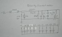
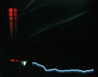
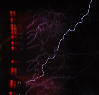
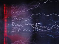
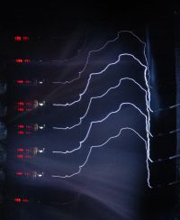


Print this page