Tuning tricks, poles etc.
Uspring, Fri Sept 06 2013, 09:22AMI've used some data provided by Steve Ward to show the effect of the 'tuning trick' he described.

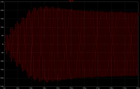
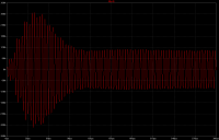
The diagrams below show the primary current of a simulation. In the first diagram the coil is made to run at the upper pole. In the second, the coil is run 'conventionally' at the lower pole.


In lower pole operation there is a surge of primary current due to the fact, that the coil is strongly out of tune before arc loading begins. Afterwards the arc pulls the coil into tune, so that current drops low. In upper pole operation that is pretty much reversed. The coil is close to tune initially but then gets somewhat out of tune later. This is desirable, since otherwise there would not be much primary current available to lengthen arcs in QCW operation.
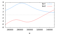
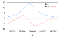
Below are 2 diagrams, which show the real (blue) and imaginary (red) parts of the primary impedance (ohms) as a function of frequency. These diagrams show the behaviour when the currents have settled to their final states. Zero current switching occurs, if primary current and input voltage are in phase, i.e. when the red curve crosses 0.


The difference between the 2 diagrams is caused by the heavier arc loading in upper pole operation. There the coil runs at about 330kHz. Primary impedance is about 2 ohms. In lower pole operation the frequency is 270kHz and the primary impedance about 4 ohms. This difference in impedance causes higher primary currents in upper pole mode.
The ultimate tuning trick, which keeps primary currents as low as possible, would be to measure the phase between primary and secondary current and keep it at 90 degrees by adjusting frequency. That involves hard switching, though.
I've been wondering, if the initial surge of primary current is bad, when working with non QCW coils. The primary tank accumulates a lot of energy, which leads to a power surge to the secondary at the point, when the secondary is pulled into tune and then empties the primary tank of its energy. This can easily double peak power output compared to what the input from the bus provides. This effect can be enhanced by using large primary inductances since the energy stored in an inductance is 0.5 * L * I^2. Max transistor currents could stay limited, but burst length would have to be increased due to the slower rampup of primary current. One could e.g. double the primary inductance, halve the MMC, double the burst length and then would have twice the energy in the primary tank.
Has anybody tried that?
Re: Tuning tricks, poles etc.
Steve Conner, Fri Sept 06 2013, 10:01AM
Yes, since I used a PLL driver on my DRSSTC, I could select which pole to use and even swap between them during a run to compare the effects.
The effects I saw were consistent with your explanation. In particular, operating on the lower pole frequency gave trouble with racing sparks and flashovers, as you might expect from a sudden dump of energy into the secondary.
I settled on the upper pole frequency for all my DRSSTCs because it seemed to give smoother and more controllable operation, not to mention much more spark output before the flashovers started. The sudden energy dump seemed to be more of a liability than an asset.
I always argued that a DRSSTC should be designed to transfer energy straight from the electrolytic bus caps to the streamer load, with the coils just operating as a matching network. It gives more spark length per dollar than a design that charges up the primary tank circuit like a classic spark-gap coil and then dumps it into the secondary, because electrolytic caps are cheaper per joule stored than film/foil ones. It also allows increasing the burst length without limit to get apocalyptic super-bangs.
As an aside: For a musical coil you want a smooth correspondence between burst length and spark loudness. Upper pole operation seems to help with this too. On the lower pole, as the burst length is increased the output jumps suddenly from a tiny fizzle to a big bang.
Steve Conner, Fri Sept 06 2013, 10:01AM
Uspring wrote ...
I've been wondering, if the initial surge of primary current is bad, when working with non QCW coils. The primary tank accumulates a lot of energy, which leads to a power surge to the secondary at the point, when the secondary is pulled into tune and then empties the primary tank of its energy. This can easily double peak power output compared to what the input from the bus provides. This effect can be enhanced by using large primary inductances since the energy stored in an inductance is 0.5 * L * I^2. Max transistor currents could stay limited, but burst length would have to be increased due to the slower rampup of primary current. One could e.g. double the primary inductance, halve the MMC, double the burst length and then would have twice the energy in the primary tank.
Has anybody tried that?
Yes, since I used a PLL driver on my DRSSTC, I could select which pole to use and even swap between them during a run to compare the effects.
The effects I saw were consistent with your explanation. In particular, operating on the lower pole frequency gave trouble with racing sparks and flashovers, as you might expect from a sudden dump of energy into the secondary.
I settled on the upper pole frequency for all my DRSSTCs because it seemed to give smoother and more controllable operation, not to mention much more spark output before the flashovers started. The sudden energy dump seemed to be more of a liability than an asset.
I always argued that a DRSSTC should be designed to transfer energy straight from the electrolytic bus caps to the streamer load, with the coils just operating as a matching network. It gives more spark length per dollar than a design that charges up the primary tank circuit like a classic spark-gap coil and then dumps it into the secondary, because electrolytic caps are cheaper per joule stored than film/foil ones. It also allows increasing the burst length without limit to get apocalyptic super-bangs.

As an aside: For a musical coil you want a smooth correspondence between burst length and spark loudness. Upper pole operation seems to help with this too. On the lower pole, as the burst length is increased the output jumps suddenly from a tiny fizzle to a big bang.
Re: Tuning tricks, poles etc.
Uspring, Fri Sept 06 2013, 12:51PM
My spark model seems to indicate, that for spark length it is advantageous to spend the bang energy in a short power surge instead of a longer more even release. Lower pole mode would just do that. The simulation might be wrong, though.
If I tune my primary only a little bit low, the simulations show a reduced primary current peak and a larger current thereafter. It looks similar to upper pole mode. I've tried that on my coil but spark output is less this way. Possibly I need much longer bursts in that case.
Re: Tuning tricks, poles etc.
Steve Conner, Fri Sept 06 2013, 03:57PM
This might well be the case if you're trying to optimise spark length per watt of input. However if you are looking to optimise spark length per inch of secondary coil, you have to lower the peak power because a small secondary can't stand a high voltage, and then lengthen the burst to compensate.
The two design goals are conflicting and every Tesla coil is a different compromise, from John Freau's spark-gap coils at one extreme to Steve Ward's QCW at the other.
Re: Tuning tricks, poles etc.
Dr. Dark Current, Thu Sept 12 2013, 09:24AM
Hi Uspring,
you say
Where do you think the transistors will switch, before zero crossing (inductive side) or after it (capacitive)? I was trying to imagine the situation, but I can't make out where the switching transitions will occur.
Dr. Dark Current, Thu Sept 12 2013, 09:24AM
Hi Uspring,
you say
Uspring wrote ...
The ultimate tuning trick, which keeps primary currents as low as possible, would be to measure the phase between primary and secondary current and keep it at 90 degrees by adjusting frequency. That involves hard switching, though.
The ultimate tuning trick, which keeps primary currents as low as possible, would be to measure the phase between primary and secondary current and keep it at 90 degrees by adjusting frequency. That involves hard switching, though.
Where do you think the transistors will switch, before zero crossing (inductive side) or after it (capacitive)? I was trying to imagine the situation, but I can't make out where the switching transitions will occur.
Re: Tuning tricks, poles etc.
Goodchild, Thu Sept 12 2013, 03:16PM
Not necessarily, The driver I'm currently working can swing phase anywhere between 90 and 180 and still soft switches. The trick is to use ZVS rather than ZCS (very similar to class E operation). This gives you the ability to use the parasitic capacitance in the switch to commutate the current and control the rise and fall waveform. Another advantage to this driver is that like Steve's PLL I can force the coil to operate at ether pole.
Using this technique you could switch at any point in a half cycle without major losses.
As for your observations, I completely agree that less energy for more time is beneficial to operation. The smooth action of adding less energy over more time is how 90% of my DRSSTCs operate. However rather than doing it with tuning I simply use a higher impedance tank to control the current ring-up. This typically allows for higher coupling without flashing over. In my large DR the coupling is actually almost 0.23k, this kind of coupling wouldn’t be possible with a faster ring-up of the primary current like in most DRSSTC.
Part of the initial surge of current in the QCW is waiting for the voltage on top load to reach a point such that it can break out. In A DRSSTC it's typically not noticeable because this breakout voltage is reached in the first half cycle in most cases. However in the QCW typically 10's to 100's of cycles are needed before this voltage is reached. Until it does break out, the current rings up very fast due to the Q being so high from lack of arc loading.
Also what you are explain using a high impedance tanks with lots of L is how I already run most of my DRs as I was talking about above. I think it's a great method and I have achieved some wonderful results using it.
Udo, you always manage to post such great topics!
Goodchild, Thu Sept 12 2013, 03:16PM
Uspring wrote ...
The ultimate tuning trick, which keeps primary currents as low as possible, would be to measure the phase between primary and secondary current and keep it at 90 degrees by adjusting frequency. That involves hard switching, though.
The ultimate tuning trick, which keeps primary currents as low as possible, would be to measure the phase between primary and secondary current and keep it at 90 degrees by adjusting frequency. That involves hard switching, though.
Not necessarily, The driver I'm currently working can swing phase anywhere between 90 and 180 and still soft switches. The trick is to use ZVS rather than ZCS (very similar to class E operation). This gives you the ability to use the parasitic capacitance in the switch to commutate the current and control the rise and fall waveform. Another advantage to this driver is that like Steve's PLL I can force the coil to operate at ether pole.
Using this technique you could switch at any point in a half cycle without major losses.
As for your observations, I completely agree that less energy for more time is beneficial to operation. The smooth action of adding less energy over more time is how 90% of my DRSSTCs operate. However rather than doing it with tuning I simply use a higher impedance tank to control the current ring-up. This typically allows for higher coupling without flashing over. In my large DR the coupling is actually almost 0.23k, this kind of coupling wouldn’t be possible with a faster ring-up of the primary current like in most DRSSTC.
Uspring wrote ...
I've been wondering, if the initial surge of primary current is bad, when working with non QCW coils. The primary tank accumulates a lot of energy, which leads to a power surge to the secondary at the point, when the secondary is pulled into tune and then empties the primary tank of its energy. This can easily double peak power output compared to what the input from the bus provides. This effect can be enhanced by using large primary inductances since the energy stored in an inductance is 0.5 * L * I^2. Max transistor currents could stay limited, but burst length would have to be increased due to the slower rampup of primary current. One could e.g. double the primary inductance, halve the MMC, double the burst length and then would have twice the energy in the primary tank.
Has anybody tried that?
Part of the initial surge of current in the QCW is waiting for the voltage on top load to reach a point such that it can break out. In A DRSSTC it's typically not noticeable because this breakout voltage is reached in the first half cycle in most cases. However in the QCW typically 10's to 100's of cycles are needed before this voltage is reached. Until it does break out, the current rings up very fast due to the Q being so high from lack of arc loading.
Also what you are explain using a high impedance tanks with lots of L is how I already run most of my DRs as I was talking about above. I think it's a great method and I have achieved some wonderful results using it.
Udo, you always manage to post such great topics!
Re: Tuning tricks, poles etc.
Uspring, Fri Sept 13 2013, 09:17AM
Dr. DC wrote:
For heavy arc loads (upper diagram), the primary will look more inductive, if its res frequency is below that of the secondary and more capacitive, if its the other way around. For intermediate loads, the wiggle in the red curve makes the phase between primary voltage and current difficult to predict. The change of secondary res frequency due to arc growth makes that worse.
Eric:

Does that allow you to safely switch at any time?
Uspring, Fri Sept 13 2013, 09:17AM
Dr. DC wrote:
Where do you think the transistors will switch, before zero crossing (inductive side) or after it (capacitive)? I was trying to imagine the situation, but I can't make out where the switching transitions will occur.I don't have a precise answer to that. In the lower impedance diagram (light arc load), the red curve (imaginary part of primary impedance) crosses zero at the point where the blue curve is max, which is also the point, where you have 90 degrees phase shift between primary and secondary current. At this point you have ZCS.
For heavy arc loads (upper diagram), the primary will look more inductive, if its res frequency is below that of the secondary and more capacitive, if its the other way around. For intermediate loads, the wiggle in the red curve makes the phase between primary voltage and current difficult to predict. The change of secondary res frequency due to arc growth makes that worse.
Eric:
Not necessarily, The driver I'm currently working can swing phase anywhere between 90 and 180 and still soft switches. The trick is to use ZVS rather than ZCS (very similar to class E operation). This gives you the ability to use the parasitic capacitance in the switch to commutate the current and control the rise and fall waveform. Another advantage to this driver is that like Steve's PLL I can force the coil to operate at ether pole.Now that you mention it, I remember some of your posts about this. It probably slipped my mind, because I never understood it.

Does that allow you to safely switch at any time?
Re: Tuning tricks, poles etc.
Dr. Dark Current, Fri Sept 13 2013, 12:49PM
Eric, I would think the parasitic capacitances in the switches can't slow down the transitions enough to decrease the turn-off losses, it is still hard switching. You would need to add external capacitance, but then if the tank circuit will look capacitive just for a moment, you are in trouble because the caps discharge right into the transistors.
Re: Tuning tricks, poles etc.
Steve Conner, Fri Sept 13 2013, 04:15PM
Yes, there's an acceptable range of load impedances for ZVS, and capacitive loads aren't in it. :o
Steve Conner, Fri Sept 13 2013, 04:15PM
Yes, there's an acceptable range of load impedances for ZVS, and capacitive loads aren't in it. :o
Re: Tuning tricks, poles etc.
Goodchild, Fri Sept 13 2013, 04:29PM
Yes you are correct in that typically some extra C is added, usually a couple extra nF depending on how slow you want the rise and fall times to be. The system can switching almost anywhere as long as enough current is flowing at the time of turn on or turn off to commutate the voltage. The only time ZVS typically will no fully ZVS is at the very beginning of a burst when the current is not high enough to fully commutate the voltage. This is generally not an issue because the current is usually low at this point anyway and wont constitute much in losses.
Udo, the basic idea is that you use the current flowing in the tank to charge or discharge the capacitors across the switches, when a cap is fully charged or discharged, you have basically forced the voltage across that cap (and the switch) to ether 0V or the +rail voltage (depending on if you are turning on or off). This way the switch turns on or off with no potential across it when it goes to switch, hence zero volts.
Re: Tuning tricks, poles etc.
Uspring, Mon Sept 16 2013, 10:55AM
Eric wrote:
Uspring, Mon Sept 16 2013, 10:55AM
Eric wrote:
Udo, the basic idea is that you use the current flowing in the tank to charge or discharge the capacitors across the switches, when a cap is fully charged or discharged, you have basically forced the voltage across that cap (and the switch) to ether 0V or the +rail voltage (depending on if you are turning on or off). This way the switch turns on or off with no potential across it when it goes to switch, hence zero volts.Thank you for the explanation. If you keep phase shift between primary and secondary current to 90 degrees as suggested above, the coil will run nearly at the seccondary res frequency. If the primary is tuned low, so that the secondary res f is always above the primary res f, the primary tank will look inductive, so that ZVS could be employed.
Print this page