
DRSSTC project From Italy
JoeBonanno, Thu Jun 06 2013, 01:00PMHi to all!
i'm Joe, writing from Italy.
From few weeks i'm planning to build a DRSSTC. Is the fist time for me around Solid State. i had build a lot of classic Spark Gap TC and Vacuum Tubes TC, using from little PL519 tube, to Big GU81M!
i decided to walk through the Solid State Universe after have watching some interesting videos on YouTube. it's incredible the capabilities of SSTC compared to an Classical spark gap Tesla!
So, i started to browse some website and acquires all the info that i need. At this time this is the state of the project:
Studying over and realization of Steve Ward UD (Eric Goodchild 2.5 Relase)

(tested and run Great!!)
Interrupter, classical BPS-PW and Burst Mode (Custom PCB)

(Tested, soon with Tosling Optic Fiber Transmitter!)
OCD and FB-CT 1:1000

(soon Gate Transf. and measure Transf.)
2X 6000uF 400V Capacitor

2 different type of large IGBT, Semitrans SKM300GB12T4 and 403GB128D

( i'm planing to use the first ones, but i accept suggestion!)
I have also 25AWG (0.45mm) wire for the secondary, i calculated winding for obtain about 40Khz Toploaded!
it's all for the moment!
thanks for comprehension for my bad english and i accept all critics or suggestions!
Joe!
Re: DRSSTC project From Italy
HV Enthusiast, Thu Jun 06 2013, 01:55PM
Very nice work! Thanks for sharing the photos. I love seeing what others are doing in the DRSSTC world on the other side of the pond! Keep up the good work!
HV Enthusiast, Thu Jun 06 2013, 01:55PM
Very nice work! Thanks for sharing the photos. I love seeing what others are doing in the DRSSTC world on the other side of the pond! Keep up the good work!
Re: DRSSTC project From Italy
Physics Junkie, Thu Jun 06 2013, 05:19PM
Cool! Everything looks good. No inductor on the UD, so you are not going to be using phase lead? (or was that just for testing purposes?) Just make sure to keep all your BUS and bridge connections tight and short to maintain lowest possible inductance.
Mind if I ask, what are the dimensions going to be for your secondary and topload?
Re: DRSSTC project From Italy
JoeBonanno, Thu Jun 06 2013, 06:08PM
Yes, i planing to use Phase Lead but i have some problem to find variable inductors in Italy at the moment. but i will use it! actually just for testing purposes!!
Yes, short connection for lowest BUS inductance!! short as i can! For this reason i think to use SKM300GB12T4, its seems to be easier for short connection. and a little more fast and powerfull!!
I'm here for have suggestion and help, so.....sure.... i planing to use 250mm Diameter and 1000mm Eight using 0,45mm (25AWG) wire. My software say:
- 70,90khz of resonant f.
- 42,97khz of quarter wavelength
- 31,78pF Toroid capacitance required
its correct?
Re: DRSSTC project From Italy
Physics Junkie, Thu Jun 06 2013, 07:17PM
Yeah that's all correct. I tried deepfriedneon.com with the dimensions and got 41kHz. So its right on target.
Physics Junkie, Thu Jun 06 2013, 07:17PM
Yeah that's all correct. I tried deepfriedneon.com with the dimensions and got 41kHz. So its right on target.
Re: DRSSTC project From Italy
HV Enthusiast, Fri Jun 07 2013, 12:41AM
If you're willing to pay just the postage, i'll send you some variable inductors.
HV Enthusiast, Fri Jun 07 2013, 12:41AM
JoeBonanno wrote ...
Yes, i planing to use Phase Lead but i have some problem to find variable inductors in Italy at the moment. but i will use it! actually just for testing purposes!!
Yes, short connection for lowest BUS inductance!! short as i can! For this reason i think to use SKM300GB12T4, its seems to be easier for short connection. and a little more fast and powerfull!!
I'm here for have suggestion and help, so.....sure.... i planing to use 250mm Diameter and 1000mm Eight using 0,45mm (25AWG) wire. My software say:
- 70,90khz of resonant f.
- 42,97khz of quarter wavelength
- 31,78pF Toroid capacitance required
its correct?
If you're willing to pay just the postage, i'll send you some variable inductors.
Re: DRSSTC project From Italy
JoeBonanno, Fri Jun 07 2013, 10:38AM
Really "EasternVoltageResearch" ?? thanks!!!
how can i send you the necessary money?
@Physics Junkie: very cool website, full of information and guideline! i usually use "Tesla Coil CAD" and "Tesla Map" (Google helps!!)
but,actually i have a doubt! i have bought 0,45mm wire double isolation and the final spessore is 0,50mm. Making calculation i have to consider 0,05mm of turns spacing, right?? final Freq. can change!!
And, how can i calculate the dimension and capacitance of this kind of toroid? Toroid
i have to consider it like a single solid toroid (classical way) or multi mini toroid parallel?
Thanks!
Re: DRSSTC project From Italy
Steve Conner, Fri Jun 07 2013, 11:18AM
I like the 128 series bricks! :)
I believe the skeleton toroid has almost the same capacitance as a solid toroid.
Steve Conner, Fri Jun 07 2013, 11:18AM
I like the 128 series bricks! :)
I believe the skeleton toroid has almost the same capacitance as a solid toroid.
Re: DRSSTC project From Italy
HV Enthusiast, Fri Jun 07 2013, 02:08PM
Just contact me via PM and send me your mailing address.
If the shipping is under a few bucks, don't worry a bout it. I'll send you the inductors and some free stickers.
HV Enthusiast, Fri Jun 07 2013, 02:08PM
wrote ...
Really "EasternVoltageResearch" ?? thanks!!!
how can i send you the necessary money?
Really "EasternVoltageResearch" ?? thanks!!!
how can i send you the necessary money?
Just contact me via PM and send me your mailing address.
If the shipping is under a few bucks, don't worry a bout it. I'll send you the inductors and some free stickers.
Re: DRSSTC project From Italy
Physics Junkie, Fri Jun 07 2013, 04:58PM
I would trust the TeslaCAD and Teslamap to be more accurate , JavaTC is another good one. I've always used 0 for the spacing between turns, but doing it your way might be more accurate. I find it to be negligable, only ever making a difference of one or two kHz. I know that JavaTC usually takes this into account anyways, showing spacing between turns to be something like 0.0008 inches. The best way to find your secondary +top load frequency is with an oscilloscope and function generator.
Physics Junkie, Fri Jun 07 2013, 04:58PM
JoeBonanno wrote ...
@Physics Junkie: very cool website, full of information and guideline! i usually use "Tesla Coil CAD" and "Tesla Map" (Google helps!!)
but,actually i have a doubt! i have bought 0,45mm wire double isolation and the final spessore is 0,50mm. Making calculation i have to consider 0,05mm of turns spacing, right?? final Freq. can change!!
And, how can i calculate the dimension and capacitance of this kind of toroid? Toroid
i have to consider it like a single solid toroid (classical way) or multi mini toroid parallel?
Thanks!
I would trust the TeslaCAD and Teslamap to be more accurate , JavaTC is another good one. I've always used 0 for the spacing between turns, but doing it your way might be more accurate. I find it to be negligable, only ever making a difference of one or two kHz. I know that JavaTC usually takes this into account anyways, showing spacing between turns to be something like 0.0008 inches. The best way to find your secondary +top load frequency is with an oscilloscope and function generator.
Re: DRSSTC project From Italy
JoeBonanno, Fri Jun 14 2013, 09:14AM
Some upgrade!
i just tested the driver with Funtion Generator for simulate primary oscillation and connecting the interrupter with Toslink optic fiber!
some photos!

here the setup, on the left side, optic fiber, interrupter with Sharp audio optic fiber transmitter.

the Driver and my little generator! actually is a Terry Fritz Coil Tuner.....perfect for generate the signal i need!

the output of the driver, here you can see the 5% duty of interrupter.....seems to be good!

and the last one, a particular of 5% on time! Single Phase without gate transformer attached!
suggestions? Critics?
Thanks!
JoeBonanno, Fri Jun 14 2013, 09:14AM
Some upgrade!
i just tested the driver with Funtion Generator for simulate primary oscillation and connecting the interrupter with Toslink optic fiber!
some photos!

here the setup, on the left side, optic fiber, interrupter with Sharp audio optic fiber transmitter.

the Driver and my little generator! actually is a Terry Fritz Coil Tuner.....perfect for generate the signal i need!

the output of the driver, here you can see the 5% duty of interrupter.....seems to be good!

and the last one, a particular of 5% on time! Single Phase without gate transformer attached!
suggestions? Critics?
Thanks!
Re: DRSSTC project From Italy
Goodchild, Sun Jun 16 2013, 07:38AM
Not sure if you have seen my most recent post on the UD2.5 but you should add a pull down resistor on the AND diode fiber junction, unless of course you bypassed the network altogether for your Toshlink RX unit.
Goodchild, Sun Jun 16 2013, 07:38AM
Not sure if you have seen my most recent post on the UD2.5 but you should add a pull down resistor on the AND diode fiber junction, unless of course you bypassed the network altogether for your Toshlink RX unit.
Re: DRSSTC project From Italy
JoeBonanno, Mon Jun 17 2013, 11:06AM
Yes.....resistor added! you can see it just between the led connector and the 74hc14! i also cuts out the traces for the OPF optic! now i have like a single optic reciever directly to 74hc14 and diode! more easy!
JoeBonanno, Mon Jun 17 2013, 11:06AM
Yes.....resistor added! you can see it just between the led connector and the 74hc14! i also cuts out the traces for the OPF optic! now i have like a single optic reciever directly to 74hc14 and diode! more easy!
Re: DRSSTC project From Italy
JoeBonanno, Mon Mar 10 2014, 04:27PM
Hi everyone
i recently resume the project for try to carry forward.
Finally i found the HFBR 2412 RX and TX module from USA (is hard to find it in Italy, and very expensive!), and i'm rebuilding the interrupter using Steve Conner suggestions!
now i need forum help to solve a problem that i seems to have in the driver.
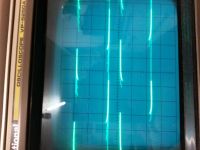
using 2 O-scope probe (initially i had only one), yesterday i tryed to visualize the 2 output signal togheter and something strange happens! The output signal are the same in both output and not opposite! Trying to find the problem, i start to go aback with the signal and i found a strange output from TL3116!
Probing the two output i found that the out at pin 7 is rigth, but the negative one at pin 8 is not negate! seems that the TL3116 give out two identical out that cause the incongruent final output ad the mosfet!
First of all, i supposed the chip was broken, but in the other driver assembled last week i found the same problem! so.....or i'm very unlucky or something that i can't interpret happen!
can someone help me?
here the output wave! Sorry for my old o-scope
thanks!
Joe

Re: DRSSTC project From Italy
Mads Barnkob, Mon Mar 10 2014, 09:16PM
Resized pictures to the maximal allowed 600 pixels width.
Mads Barnkob, Mon Mar 10 2014, 09:16PM
Resized pictures to the maximal allowed 600 pixels width.
Re: DRSSTC project From Italy
JoeBonanno, Wed Mar 12 2014, 06:03PM
Thanks Mads! and Sorry!
maybe the damage was found! the TL3116 seems to be broken, i test it with accidentaly with 5v and not 1V as OCT normally give out! i'm waiting for a new one chip for replace and test it!
JoeBonanno, Wed Mar 12 2014, 06:03PM
Thanks Mads! and Sorry!
maybe the damage was found! the TL3116 seems to be broken, i test it with accidentaly with 5v and not 1V as OCT normally give out! i'm waiting for a new one chip for replace and test it!
Re: DRSSTC project From Italy
JoeBonanno, Wed Apr 30 2014, 06:07PM
Finally i got my driver to fully functionality, the problem was very idiot, only my Function generator that became crazy! buu
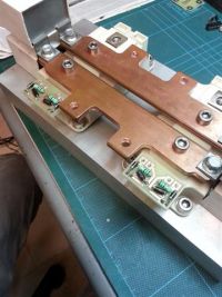
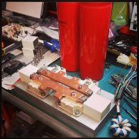
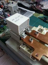
with the driver tested, i started to design and assemble the bridge, with the two Semikron 300 series.
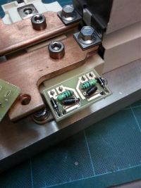
one my friend found for me a perfect copper bar of 4mm thick that i cut and modelling (by hand) for connect the two IGBT, Bus capacitors, and snubber!
i'm planning to use 4 Italcond 10.000uF 450V series and parallel for obtain 10.000uF at 900V. For snubber, i have 4 1,5uF 1Kv caps. maybe to much, but, in Latin "Melius abundare quam deficere"!
i don't like to solder components without PCB so i decided to create a little one for gate protection bidirectional diode, resistor and discarge diode.
next step is to fix bus capacitors, rewind the definitive GDT, and try to test the waveforms!


Re: DRSSTC project From Italy
JoeBonanno, Wed May 21 2014, 06:38AM
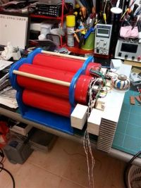
Bridge finished!!
Now is time to assemble the MMC and wire the driver box!
JoeBonanno, Wed May 21 2014, 06:38AM
Bridge finished!!
Now is time to assemble the MMC and wire the driver box!

Re: DRSSTC project From Italy
HV Enthusiast, Thu May 22 2014, 12:28PM
Looks great!
Just try to add in some passive and active bleed resistors across those capacitors for safety. 900V at those energy levels will kill!
A 20k-50k passive bleeder should be good across each capacitor (size the resistor accordingly) as a backup.
And as a primary discharge, you can use a normally closed relay (which is turned ON when input power is applied) to put a smaller value resistor directly across the bus to discharge the entire bus in several seconds when power is removed. I try to size the resistor to reduce voltage to less than 30V in 5 seconds. (I believe 2 seconds is the industry safety standard, but 5 seconds is enough generally as it will take you longer to walk to the coil than 5 seconds after power is removed)
Re: DRSSTC project From Italy
JoeBonanno, Sat May 24 2014, 06:24AM
Thanks for the suggestions EVR! Yes, is a very good idea to use a relay for self discharge the bus capacitors! you know? after have tested the capacitors 1 month ago, discharged it to 0, leave it one night short circuited......when i assembled the bridge last week, the capacitors have inside 16V of charge!!! Very scary!!!
now i'm waiting for your universal MIDI interrupter to arrive! And the large ferrite! the ferrite that i have is not to large for big primary cable!
The MMC is almost ready, 380nF at 5Kv. Maybe the voltage is undersized, but are made from very hi quality PP hi current capacitors, made for industrial resonant inverter. bah, is a test, if it fails or melt, i try to find a more bigger and strong caps!
oh, i'm thinking, i can use the same relay discharge system for start up slow charge! i need only a on-delay circuit. when i turn on the power, the relay stay engaged for few seconds slow charging the capacitors, and then....open! and you are ready for use! when the power is removed...it works as discharge system! what do you think about?
Joe!
Re: DRSSTC project From Italy
JoeBonanno, Thu Jan 15 2015, 04:33PM
Hi to all
some small news in building up my DR.
the bridge was finished, the U.D. 2.5 tuned and installed inside a metal enclosure.
here some wave form with phase lead added!
Wave
down here one medium power test, 670A 170V on bus, without secondary coil. This is gate signal, not bridge Output.
about the spike on the red signal, we supposed to be noise......or.....we hope to be! but, till now, it work great.
Wave 2
Now it's time to build up primary and secondary coils.
I choice the following parameter for secondary:
Diameter 250mm
Height 1000mm
wire 0.45mm
approximate resonant freq 1/4 wave 43khz
approximate impedance of resonant system 80k (about)
for primary, i have some questions and doubts:
the idea was to build a conical primary with 40° angle, about 8 turns of 12mm diameter copper pipe.
but, yesterday i saw the new design of primary from ArcAttack and Ward. The toroidal style one! It look amazing.
the idea was to test this king of design, but i'm scared about coupling. You know that i always build spark gap tesla coil that don't like to much coupling, is't the same with DRSSTC or i can rise it making a conical or toroidal primary?
this is the most important doubt that i have, i hope that someone can help me and explain the theory about it!
thanks
Joe
Re: DRSSTC project From Italy
Graham Armitage, Thu Jan 15 2015, 06:52PM
Joe, in the Wave2 photo - is the red trace the bridge output? I am guessing the yellow one is a feedback CT correct?
Graham Armitage, Thu Jan 15 2015, 06:52PM
Joe, in the Wave2 photo - is the red trace the bridge output? I am guessing the yellow one is a feedback CT correct?
Re: DRSSTC project From Italy
JoeBonanno, Thu Jan 15 2015, 07:10PM
in all two photos the red trace is one gate of low side IGBT, the yellow one is a feedback TC that i use for current monitoring, 1:1000 with 12R burden resistor!if i have time, this week i will check the bridge output. i find a isolation transformer for line input for clean the noise coming from 230V line.
Re: DRSSTC project From Italy
JoeBonanno, Mon Jan 19 2015, 04:11PM
Today, while make some testing of the bridge, playing some midi and have fun heating some metal inside the primary, i decided to push the system up to 1kA at 230V for see if it's stable. My Current Transformer loaded with 10R resistor give out 20Vpp. I can earn the sound of vibration of a iron plate inside the primary and see the light of laboratory lo down...very down!! but, i notice that the OC protection do not trigger! strange! i tried to rise up to 1.1kA for a second....but nothing happened! so i open the driver box and start to turn down the trimmer and after few turns the OC start to trigger instantaneously when i rise a bit the duty, less than 100A! and nothing change if i turn back the previously position! so, what happened? maybe comparator failure? is boring but i need to disassembly the driver box for find the issue!
Re: DRSSTC project From Italy
Wolfram, Mon Jan 19 2015, 04:49PM
Make sure that your OCD setpoint voltage is within the common mode input range of the comparator. If the OCD comparator is an LM311 running from 5V, the setpoint should be somewhere between 1.2 V and 3.5 V for the comparator to work correctly. Decrease the current transformer burden resistor if needed.
Re: DRSSTC project From Italy
JoeBonanno, Tue Jan 20 2015, 08:31AM
Found the problem. for some unknown reason the trimmer remain hold at low position!
JoeBonanno, Tue Jan 20 2015, 08:31AM
Found the problem. for some unknown reason the trimmer remain hold at low position!
Re: DRSSTC project From Italy
JoeBonanno, Thu Jan 29 2015, 11:14AM
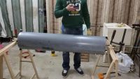
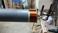
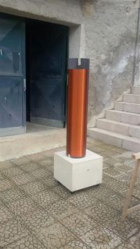
Some update! After have fixed the driver OCD i started to build up the secondary coil.
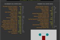
1050mm hight x 250mm diameter, 0.45 wire ( 41in x 9.8in AWG 25.8)
here some pictures of secondary, enclosure and JacaTC table!

other images!
JoeBonanno, Thu Jan 29 2015, 11:14AM
Some update! After have fixed the driver OCD i started to build up the secondary coil.
1050mm hight x 250mm diameter, 0.45 wire ( 41in x 9.8in AWG 25.8)
here some pictures of secondary, enclosure and JacaTC table!


other images!

Re: DRSSTC project From Italy
JoeBonanno, Wed Feb 04 2015, 05:21PM
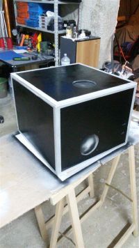
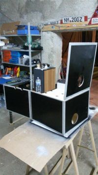
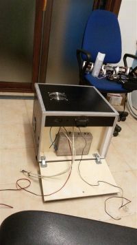
some painting and final assembling!
i choose Powercon for 600V supply and standard computer connector for 230V auxiliary.
two HP big fan, one push air on the MMC and the other one, directly on IGBT heatsink push out. This two are able to create an awesome flux of air inside the cabinet!
As a discharge protection i will install a relay that which bus capacitor on a big resistor when i unplug power and stay hold until next uses!
photos


Print this page