
Junky QCW
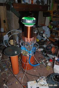
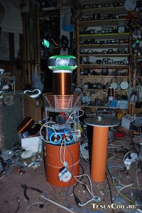
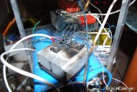
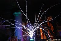
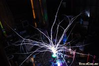
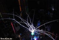
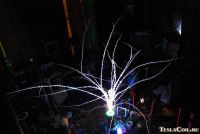
zrg, Fri May 03 2013, 08:51PMJust wanted to share some nice shots of a QCW DRSSTC test rig we've been updating today. Originally it had a buck with IRGP50B60PD1, and a bridge with same IGBTs, now updated to a double bridge, and a boost converter before the buck (again on 50B60), which rises the voltage to ~410VDC and charges the 2x12000uf CDE electrolytics.
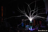
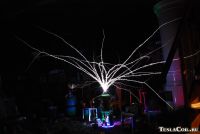
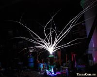
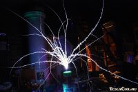
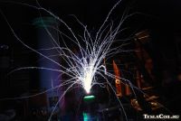
125x250 mm secondary with a ~420 kHz freq gives nice 2+ meter swordlike sparks, maximum recorded shot is ~220 cm.
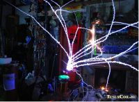
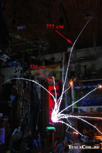
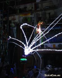
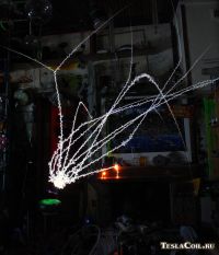
The current limiter is set to 300A, which gives us ~60 kW of peak power through buck. It's amazing how much these small transistors can withstand
 However, in the end it banged with several kJ from lytics coming into my poor ears.
Re: Junky QCW
HV Enthusiast, Fri May 03 2013, 09:20PM
Very, very sweet!!!
I absolutely love it. That coil has true SOUL!!!!
Your work area reminds me of the late legendary Jim Williams' famous work bench.

You are both true masters of analog electronics!!!!!
HV Enthusiast, Fri May 03 2013, 09:20PM
Very, very sweet!!!
I absolutely love it. That coil has true SOUL!!!!
Your work area reminds me of the late legendary Jim Williams' famous work bench.

You are both true masters of analog electronics!!!!!
Re: Junky QCW
RateReducer, Sat May 04 2013, 12:29PM
This is just amazing!
RateReducer, Sat May 04 2013, 12:29PM
This is just amazing!

Re: Junky QCW
zzz_julian_zzz, Sat May 04 2013, 12:53PM
Hi, how long are the ramp you are using? thanks for sharing this wonderful coil! very great!
zzz_julian_zzz, Sat May 04 2013, 12:53PM
Hi, how long are the ramp you are using? thanks for sharing this wonderful coil! very great!
Re: Junky QCW
zilipoper, Sat May 04 2013, 01:13PM
Ho Ho Ho worthy of
zilipoper, Sat May 04 2013, 01:13PM
Ho Ho Ho worthy of
Re: Junky QCW
loneoceans, Sat May 04 2013, 01:39PM
Wow zrg, that looks fantastic!
loneoceans, Sat May 04 2013, 01:39PM
Wow zrg, that looks fantastic!
Re: Junky QCW
zrg, Sat May 04 2013, 01:49PM
Variable 10-20 ms, shots are made at ~15 ms
zrg, Sat May 04 2013, 01:49PM
zzz_julian_zzz wrote ...
Hi, how long are the ramp you are using? thanks for sharing this wonderful coil! very great!
Hi, how long are the ramp you are using? thanks for sharing this wonderful coil! very great!
Variable 10-20 ms, shots are made at ~15 ms
Re: Junky QCW
zzz_julian_zzz, Sat May 04 2013, 03:13PM
HI Zrg, thanks for the reply..
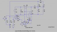
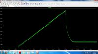
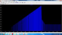
actually, im current assembling my QCW bus modulator, could you give me some advice with my schematic below? i only have LM311 (voltage comparator) this is the only Voltage comp available here in my country... I used the first one to make the 'hysterizer' and the other for the detector/convert to logic 1 & 0, since the output of the first LM311 is not 1 & 0 but a signal in a form of a ramp,, i would like to know if this IC(LM311) / overall circuit can work? thanks a lot.. :)


Re: Junky QCW
Mr.Black, Sat May 04 2013, 03:36PM
This is amazingï¼
Mr.Black, Sat May 04 2013, 03:36PM
This is amazingï¼
Re: Junky QCW
teravolt, Sat May 04 2013, 05:00PM
I like your lab the best but the coil piezoresistance.
teravolt, Sat May 04 2013, 05:00PM
I like your lab the best but the coil piezoresistance.
Re: Junky QCW
zrg, Sat May 04 2013, 06:18PM
zzz_julian_zzz,
I'd like to give you advice on that, but I'm using an Attiny13 for a modulator, exactly to avoid insane logics ramp generator and I highly recommend you to do the same.
zrg, Sat May 04 2013, 06:18PM
zzz_julian_zzz,
I'd like to give you advice on that, but I'm using an Attiny13 for a modulator, exactly to avoid insane logics ramp generator
 and I highly recommend you to do the same.
Re: Junky QCW
zzz_julian_zzz, Sun May 05 2013, 03:59AM
In a qcw IGBT buck(bus mod) driver circuit, why do we use opto couplers, instead of the conventional GDT like in the case of UD?? its also isolated i think..
zzz_julian_zzz, Sun May 05 2013, 03:59AM
In a qcw IGBT buck(bus mod) driver circuit, why do we use opto couplers, instead of the conventional GDT like in the case of UD?? its also isolated i think..
Re: Junky QCW
Goodchild, Sun May 05 2013, 08:35AM
Great work my friend, amazing output.
May I ask what parts you used in the inverter and how you cooled them? Everyone seems to have a different view on how they should be build, i'm curios to see how you did it.
Because GDTs have a limited range of duty cycle they can run, if you start to run over or under 50% you will start to level shift the output. Also once you get close to 100% or 0% the core will saturate.
In a modulator you need a wide duty cycle range to operate properly.
Goodchild, Sun May 05 2013, 08:35AM
Great work my friend, amazing output.
May I ask what parts you used in the inverter and how you cooled them? Everyone seems to have a different view on how they should be build, i'm curios to see how you did it.
zzz_julian_zzz wrote ...
In a qcw IGBT buck(bus mod) driver circuit, why do we use opto couplers, instead of the conventional GDT like in the case of UD?? its also isolated i think..
In a qcw IGBT buck(bus mod) driver circuit, why do we use opto couplers, instead of the conventional GDT like in the case of UD?? its also isolated i think..
Because GDTs have a limited range of duty cycle they can run, if you start to run over or under 50% you will start to level shift the output. Also once you get close to 100% or 0% the core will saturate.
In a modulator you need a wide duty cycle range to operate properly.
Re: Junky QCW
Dr. Dark Current, Sun May 05 2013, 09:54AM
You can also full wave rectify the output of a GDT, but you need to use a simple pulse shaping circuit in front of the gate. This way you can transfer duty cycles from 0 to 100%.
Dr. Dark Current, Sun May 05 2013, 09:54AM
You can also full wave rectify the output of a GDT, but you need to use a simple pulse shaping circuit in front of the gate. This way you can transfer duty cycles from 0 to 100%.
Re: Junky QCW
zzz_julian_zzz, Sun May 05 2013, 01:47PM
Ow, thanks for clearing that out.. :)
zzz_julian_zzz, Sun May 05 2013, 01:47PM
Ow, thanks for clearing that out.. :)
Re: Junky QCW
Mads Barnkob, Sun May 05 2013, 04:31PM
Great coil you have built there Zrg, amazing sparks and amazing mess in your laboratory :D
Mads Barnkob, Sun May 05 2013, 04:31PM
Great coil you have built there Zrg, amazing sparks and amazing mess in your laboratory :D
Re: Junky QCW
Steve Conner, Sun May 05 2013, 09:00PM
Looks great! :DDD How did you combine the outputs of the two bridges?
Steve Conner, Sun May 05 2013, 09:00PM
Looks great! :DDD How did you combine the outputs of the two bridges?
Re: Junky QCW
Myke, Sun May 05 2013, 10:50PM
Great work! Always fun to see coils that give impressive results like these.
Any chance you'll have a video once you fix the blown transistors in the buck?
EDIT: Is this it?
Myke, Sun May 05 2013, 10:50PM
Great work! Always fun to see coils that give impressive results like these.
Any chance you'll have a video once you fix the blown transistors in the buck?
EDIT: Is this it?

Re: Junky QCW
Whiplash, Mon May 06 2013, 06:53PM
amazing !!!!! i want one :D
Whiplash, Mon May 06 2013, 06:53PM
amazing !!!!! i want one :D
Re: Junky QCW
zrg, Wed May 08 2013, 07:56PM
Thanks for the comments.
The buck was updated to double 50B60 and, heheh, still uses a single HFA30 diode (30A rated, 300A actual current )
)
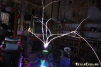
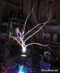
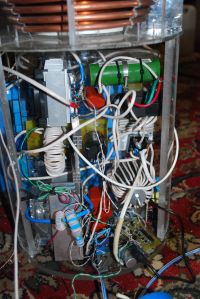
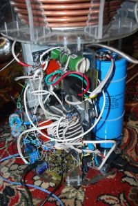
The coil was modified to a taller case to fit the schematics and the lytics. It is still junky, but less junky now. All power parts - the boost, the buck, the inductor and the bridge - are clearly visible on the photos. No cooling issues at all: the buck is <40 deg. C, the bridge is cold as ice, the boost is ~50-55 deg. C.
The MMC is ~12.5 nf.
Now I only need to place the driver and the power supply inside, and to add a precharge circuit for the 24000uf so that the boost won't explode trying to charge them at the very beginning.
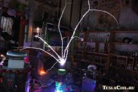
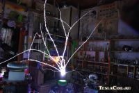
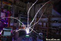
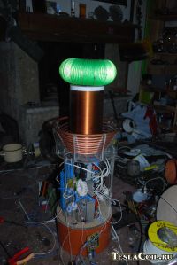
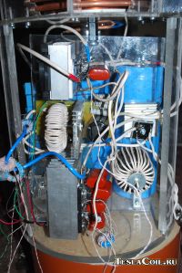
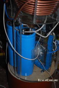
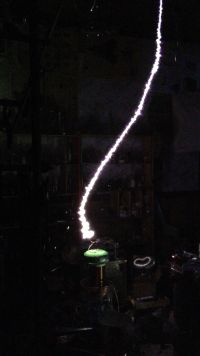
And, oh yeah GIF:
zrg, Wed May 08 2013, 07:56PM
Thanks for the comments.
The buck was updated to double 50B60 and, heheh, still uses a single HFA30 diode (30A rated, 300A actual current
 )
)The coil was modified to a taller case to fit the schematics and the lytics. It is still junky, but less junky now. All power parts - the boost, the buck, the inductor and the bridge - are clearly visible on the photos. No cooling issues at all: the buck is <40 deg. C, the bridge is cold as ice, the boost is ~50-55 deg. C.
The MMC is ~12.5 nf.
Now I only need to place the driver and the power supply inside, and to add a precharge circuit for the 24000uf so that the boost won't explode trying to charge them at the very beginning.


And, oh yeah GIF:

Re: Junky QCW
Mr.Black, Wed May 08 2013, 08:35PM
Your QCW DRSSTC looks so beautifulï¼
I have a lot of problems.I'm building a QCW DRSSTC project.Hoping to get some help.
How much the TC HBridge's bus voltage waveform slope ? It is a linear law?
How to record the tank current waveform envelope?^^
Mr.Black, Wed May 08 2013, 08:35PM
Your QCW DRSSTC looks so beautifulï¼
I have a lot of problems.I'm building a QCW DRSSTC project.Hoping to get some help.
How much the TC HBridge's bus voltage waveform slope ? It is a linear law?
How to record the tank current waveform envelope?^^
Re: Junky QCW
teravolt, Thu May 09 2013, 04:12AM
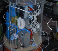
I am building a hand held version of the qcw that is about the same size as your coil and I was wondering if you would be willing to post a picture of the semiconductor face of your tesla. I was thinking of making my bridge of 4 hgtg27n120bn X 4 for a total of 16 devices do you think that it is over kill? I am trying to gauge how much power it takes to produce large sparks like your gif pictures and how big can they get. Do you think that the length of the arcs are due to the large electrolytic capacitors (energy storage) or the wall power you are supplying? thanks

Re: Junky QCW
dex, Thu May 09 2013, 10:11AM
great work and fantastic tesla coil.
generating 7' long sparks in normal atmosfere with less than 100 kV top voltage is an amazing.
dex, Thu May 09 2013, 10:11AM
great work and fantastic tesla coil.
generating 7' long sparks in normal atmosfere with less than 100 kV top voltage is an amazing.
Re: Junky QCW
Steve Conner, Thu May 09 2013, 10:25AM
Performance is amazing! Must be the green topload that does it
Steve Conner, Thu May 09 2013, 10:25AM
Performance is amazing! Must be the green topload that does it

Re: Junky QCW
Steve Ward, Fri May 10 2013, 08:32AM
Wow, totally awesome .
.
You mention 300A somewhere, which sounds about right. My original QCW managed only 6 foot sparks (~182cm) with ~270A drive, but it seemed to be going too far out of tune and i didnt have nearly the bus capacitor that you have, so it just never pushed any futher despite longer pulses. I find that adding secondary C helps with the detuning and keeps the primary current significantly lower.
I also am impressed with the size of your setup. Good old aluminum heatsinks will do the trick if the rep rate is low enough . We mainly rely on the copper tab of the TO-247 for pulses in the 20mS range, so it really comes down to if your IGBT has a big enough chip or not. It sounds like you are finding out what the absolute max pulse capacity of these IGBTs are!
Steve Ward, Fri May 10 2013, 08:32AM
Wow, totally awesome
 .
.You mention 300A somewhere, which sounds about right. My original QCW managed only 6 foot sparks (~182cm) with ~270A drive, but it seemed to be going too far out of tune and i didnt have nearly the bus capacitor that you have, so it just never pushed any futher despite longer pulses. I find that adding secondary C helps with the detuning and keeps the primary current significantly lower.
I also am impressed with the size of your setup. Good old aluminum heatsinks will do the trick if the rep rate is low enough
 . We mainly rely on the copper tab of the TO-247 for pulses in the 20mS range, so it really comes down to if your IGBT has a big enough chip or not. It sounds like you are finding out what the absolute max pulse capacity of these IGBTs are!
Re: Junky QCW
Intra, Sun May 12 2013, 10:25PM
ÐÑÑ…, ÐºÐ°ÐºÐ°Ñ Ð¾Ñ…ÑƒÐµÐ½Ð½Ð°Ñ Ñ‚ÐµÑла.. ПроÑто агонь!!!
Intra, Sun May 12 2013, 10:25PM
ÐÑÑ…, ÐºÐ°ÐºÐ°Ñ Ð¾Ñ…ÑƒÐµÐ½Ð½Ð°Ñ Ñ‚ÐµÑла.. ПроÑто агонь!!!
Re: Junky QCW
zrg, Mon May 13 2013, 02:41PM
Semi-final setup.
The doubling of electrolytics and adding a bigger topload increased the perfomance (230+) cm, but unfortunately there's no place for more capacitance inside the case.
zrg, Mon May 13 2013, 02:41PM
Semi-final setup.
The doubling of electrolytics and adding a bigger topload increased the perfomance (230+) cm, but unfortunately there's no place for more capacitance inside the case.


Re: Junky QCW
teravolt, Tue May 14 2013, 04:05AM
I think you hold the spark length to secondary height ratio record. Exhalent work, your coil is more of a work of art. Do you plan on releasing any schematics so we can better understand it?
teravolt, Tue May 14 2013, 04:05AM
I think you hold the spark length to secondary height ratio record. Exhalent work, your coil is more of a work of art. Do you plan on releasing any schematics so we can better understand it?
Re: Junky QCW
Goodchild, Tue May 14 2013, 07:38PM
Wow, that's some awesome work! And you are only using a single full bridge of transistors? Very impressive work.
Goodchild, Tue May 14 2013, 07:38PM
Wow, that's some awesome work! And you are only using a single full bridge of transistors? Very impressive work.
Re: Junky QCW
dex, Fri May 17 2013, 08:36AM
W=∫P(t)dt
assuming ~15ms ramp,and 60 kW peak power with linear rise of input power that would give:
W ~ 60kW×15ms/2 = 450 J
does this sound ok?
dex, Fri May 17 2013, 08:36AM
zrg wrote ...
The current limiter is set to 300A, which gives us ~60 kW of peak power through buck. It's amazing how much these small transistors can withstand However, in the end it banged with several kJ from lytics coming into my poor ears.
well,it would be interesting to estimate energy used to create 7' spark.The current limiter is set to 300A, which gives us ~60 kW of peak power through buck. It's amazing how much these small transistors can withstand
 However, in the end it banged with several kJ from lytics coming into my poor ears.
W=∫P(t)dt
assuming ~15ms ramp,and 60 kW peak power with linear rise of input power that would give:
W ~ 60kW×15ms/2 = 450 J
does this sound ok?
Re: Junky QCW
Uspring, Fri May 17 2013, 09:35AM
Dex wrote:
Uspring, Fri May 17 2013, 09:35AM
Dex wrote:
assuming ~15ms ramp,and 60 kW peak power with linear rise of input power that would give:If zrg ramps up voltage linearly, power consumption would rise much more steeply, more like V^4. So the total energy would be much less. If he'd use shorter bursts, the bang energy would be even less, probably at the cost of having the nice swordlike sparks.
W ~ 60kW×15ms/2 = 450 J
generating 7' long sparks in normal atmosfere with less than 100 kV top voltage is an amazing.Interesting info. Where did you get that from, I couldn't find a source?
Re: Junky QCW
Steve Conner, Fri May 17 2013, 10:06AM
Bang energies of several hundred joules are the norm for QCWs.
Steve Ward measured the topload voltage of his QCW with a high voltage probe, and got an answer of about 50kV.
Due to nonlinear streamer loading, the inverter looks somewhat like a constant current sink to the DC bus. So a linear ramp in voltage implies a linear ramp in power too.
Re: Junky QCW
dex, Fri May 17 2013, 10:27AM
for excersise,let's assume both current and voltage rise in a linear fashion (and this isn't very true for current i guess).
we would have:
i(t)~Im*t/Tr
u(t)=Um*t/Tr
P(t)=u(t)*i(t) *t²/Tr²=Pm*t²/Tr²
W=∫Pm*t²/Tr² dt=(Pm/Tr²)∫t²dt
since we integrate from t=0 to t=Tm ,the result would be:
W=Pm*Tr/3=60*15/3= 300J
dex, Fri May 17 2013, 10:27AM
Uspring wrote ...
Dex wrote:
ok,maybe less but not much less.Dex wrote:
assuming ~15ms ramp,and 60 kW peak power with linear rise of input power that would give:If zrg ramps up voltage linearly, power consumption would rise much more steeply, more like V^4. So the total energy would be much less. If he'd use shorter bursts, the bang energy would be even less, probably at the cost of having the nice swordlike sparks.
W ~ 60kW×15ms/2 = 450 J
generating 7' long sparks in normal atmosfere with less than 100 kV top voltage is an amazing.Interesting info. Where did you get that from, I couldn't find a source?
for excersise,let's assume both current and voltage rise in a linear fashion (and this isn't very true for current i guess).
we would have:
i(t)~Im*t/Tr
u(t)=Um*t/Tr
P(t)=u(t)*i(t) *t²/Tr²=Pm*t²/Tr²
W=∫Pm*t²/Tr² dt=(Pm/Tr²)∫t²dt
since we integrate from t=0 to t=Tm ,the result would be:
W=Pm*Tr/3=60*15/3= 300J
Steve Conner wrote ...
Bang energies of several hundred joules are the norm for QCWs.
Steve Ward measured the topload voltage of his QCW with a high voltage probe, and got an answer of about 50kV.
Due to nonlinear streamer loading, the inverter looks somewhat like a constant current sink to the DC bus. So a linear ramp in voltage implies a linear ramp in power too.
if i remember correctly ,he has reported something like 60 kV for 5' spark?Bang energies of several hundred joules are the norm for QCWs.
Steve Ward measured the topload voltage of his QCW with a high voltage probe, and got an answer of about 50kV.
Due to nonlinear streamer loading, the inverter looks somewhat like a constant current sink to the DC bus. So a linear ramp in voltage implies a linear ramp in power too.
Re: Junky QCW
teravolt, Fri May 17 2013, 08:01PM
Steve said he grows the spark. If the voltage is only 50 to 60kv then the spark has to be all current to get that long. It is reasonable to asume the spark length is reflective of how much energy storage, ie capacitance, there is in the ramp driver.
teravolt, Fri May 17 2013, 08:01PM
Steve said he grows the spark. If the voltage is only 50 to 60kv then the spark has to be all current to get that long. It is reasonable to asume the spark length is reflective of how much energy storage, ie capacitance, there is in the ramp driver.
Re: Junky QCW
Uspring, Sat May 18 2013, 07:57AM
Steve Conner wrote:
@dex:
I agree with your calculation of bang energy. What I meant to say is, that if you are looking for the longest sparks for a given bang energy, QCW isn't the way to go.
Uspring, Sat May 18 2013, 07:57AM
Steve Conner wrote:
Steve Ward measured the topload voltage of his QCW with a high voltage probe, and got an answer of about 50kV.Ok, I thought, the 100kV quote about zrg's sparks was based on some measurement of his.
Due to nonlinear streamer loading, the inverter looks somewhat like a constant current sink to the DC bus. So a linear ramp in voltage implies a linear ramp in power too.I confused the toroids voltage with the bus voltage. The bus voltage is the one with the linear ramp.
@dex:
I agree with your calculation of bang energy. What I meant to say is, that if you are looking for the longest sparks for a given bang energy, QCW isn't the way to go.
Re: Junky QCW
PhilGood, Sun May 19 2013, 03:17AM
Awesome Coil !
Never seen such an impressive Arc lenght / secondary lenght ratio, great job
What is the max rep rate you can run the coil at for long time without overheating ? Is there any way to increase it ?
PhilGood, Sun May 19 2013, 03:17AM
Awesome Coil !
Never seen such an impressive Arc lenght / secondary lenght ratio, great job
What is the max rep rate you can run the coil at for long time without overheating ? Is there any way to increase it ?
Re: Junky QCW
dex, Sun May 19 2013, 08:18AM
agreed, qcw is more like "the longest spark for given voltage"
but,for the sake of qcw construction one should be aware of energy requirements as well .
dex, Sun May 19 2013, 08:18AM
Uspring wrote ...
What I meant to say is, that if you are looking for the longest sparks for a given bang energy, QCW isn't the way to go.
What I meant to say is, that if you are looking for the longest sparks for a given bang energy, QCW isn't the way to go.
agreed, qcw is more like "the longest spark for given voltage"

but,for the sake of qcw construction one should be aware of energy requirements as well .
Re: Junky QCW
Steve Ward, Tue May 21 2013, 09:51PM
The last time i measured my Tesla Gun after just calibrating my HV probe, i measured the initiation voltage for corona at 39kV and the voltage required to create a spark to bridge a 56" gap to be 55kV. The data suggested a fairly linear increase in top voltage for a linear increase in spark length. So another 16kV should be required for 112" sparks is what id predict for a first order estimate. This means even super high power QCW coils shouldnt have problems with voltage standoff, other than maybe their sparks terminate to ground too easily.
I only measured the "straight spark" ramp setting, so i need to see what voltage it gets to when i ramp much faster, but id guess its only 60kV or so.
ZRG, Do you know the coupling coefficient of your tesla coil? I found this to make a big difference in the ability to make straight sparks. The coupling on my latest design is ~.26, and i think this is too low for making the sword sparks, instead i get the straight segmented sparks.
Print this page