
Universal DRSSTC Driver V2.5 (Sold Out)
Goodchild, Mon Apr 08 2013, 06:12AMWell I figured this is far enough along now that I would share it with you guys. This is a tweaked version of Steve Ward's UD2.1 (I call it the UD2.5). Basically it has all the PCB errors fixed from the UD2.1 and also has some added new features, most suggested by the people in the solid state Tesla coil community.
Probably the biggest add-on is the addition of the IFD95 fiber optic receiver. I know I lot of people use these units and now you can use it with the UD2 with no extra modifications! As an added bonus it also makes any coil compatible with interrupters using fiber of both types. The fiber units have OR operation so you can switch between using one or the other very easily.
As of now, it bench tested successively. I will put it in a DR by next week for test runs. I have high hopes!
I plan to host the board files on my website for anyone to use in the future.
Board files and notes here ->

Here is a list of changes and add-ons:
Fixed PCB error in TL3116 feedback network
Linked schematic and PCB files in eagle
Added support for industrial fiber optics IFD95T or IFD95C fiber RX units
Changed GDT primary damping resistor to larger through hole for better heat dissipation
Chained 5Vreg input to 9Vreg output for better thermal performance in 5Vreg
Rotated all Vregs 90 degrees for easy heatsinking
Added socket system for phase lead inductor for quick swap
Changed phase lead select header to allow for LR or just R burden network (for debugging)
Added optional second parallel burden resistor in OCD network for larger coils
Electrolytic capacitors changed to through hole parts
LED header labels on underside of PCB
PW limiting circuit found in UD2 has been removed
Test points added for easy reading of OCD set point voltage (TP1)
All credit goes to Steven Ward for the original design of the UD2. LONG LIVE THE UD!


UPDATE 5/8/13 REV A
Well as I said originally this is a beta board at the moment. Someone pointed out to me in an email that I forgot a pull down resistor from the diode merge junction for the fiber OR operation. I have updated the board files and posted the new files on my website under the original link.
If you have already made one of my board an easy fix can be made by kludging a 1k resistor from the output of the diode junction/AND input to ground to act as a pull down. Check the new schematic for reference (resistor R21). I found it an easy fix using the vias on the board and a 1k through hole resistor.

OK so I decided that I will be selling these boards fully assembled and tested now that I have a working reflow oven. I will be fabbing the UD2.5 Rev B boards price is as follows.
Fully assembled/Tested board -> $125 + Shipping
Board only -> $25 + Shipping
Boards will come by default with both fibers, vReg heat sink, and connectors installed. I can also do variations on this process if you are interested.
Other possible configs:
No connectors
No Fiber
Only SMD soldered
etc...
PM me if you are interested.
UD2.5 Rev B


Re: Universal DRSSTC Driver V2.5 (Sold Out)
Kizmo, Mon Apr 08 2013, 08:30AM
Looks pretty sweet.
One thing i would like to see in UD2.5 (which is something i modified to my UD1.3 build) is undervoltage shutdown. If 24V rail for gate drive drops below 23Volts, the interrupter line gets disabled with NC small signal relay.
If controller looses power it SHOULD shut down before 5V logic goes crazy or igbt gates wont have enough potential for saturation.
Re: Universal DRSSTC Driver V2.5 (Sold Out)
Steve Conner, Mon Apr 08 2013, 10:34AM
I agree so strongly that my drivers had this feature for the past 6 years.
Steve Conner, Mon Apr 08 2013, 10:34AM
I agree so strongly that my drivers had this feature for the past 6 years.
Re: Universal DRSSTC Driver V2.5 (Sold Out)
Physics Junkie, Mon Apr 08 2013, 11:29AM
Cool! I'm looking forward to the board files.
So all the parts are the same with the exception of the added FO and through hole components?
Physics Junkie, Mon Apr 08 2013, 11:29AM
Cool! I'm looking forward to the board files.
So all the parts are the same with the exception of the added FO and through hole components?
Re: Universal DRSSTC Driver V2.5 (Sold Out)
HV Enthusiast, Mon Apr 08 2013, 01:56PM
Looks great!
One suggestion on the PCB routing.
When you have segregated ground planes (power /digital) sections, make sure you have a bridge between the planes anytime you have signals going between the two.
Basically, for this, if you have two gate signals coming from your digital side and then going to the power section side, keep them close together crossing the ground break, and then on the ground plane, put a little trace underneath them that connects both ground planes. This keeps the signals tightly coupled together. Otherwise, the return for those signals will go who knows where as it tries to make it back to the source.
EMC Guru Henry Ott overs this extensively in his book which is a must have for any power engineer!
You should definately check out the following book. Its the BIBLE in EMC/EME design and would be a great asset and if you have the opportunity to attend one of Henry Ott's course, definately take it! I have taken it 3 times so far and it probably has been the best engineering class i've ever taken.
Re: Universal DRSSTC Driver V2.5 (Sold Out)
Steve Conner, Mon Apr 08 2013, 02:01PM
Henry Ott famously published a joke article, "10 ways to maximize emission from your product". He might have added #11, make your product a Tesla coil!
Steve Conner, Mon Apr 08 2013, 02:01PM
Henry Ott famously published a joke article, "10 ways to maximize emission from your product".
He might have added #11, make your product a Tesla coil! Re: Universal DRSSTC Driver V2.5 (Sold Out)
HV Enthusiast, Mon Apr 08 2013, 02:07PM
I did fire up a coil for him about 10 years ago when he visited for a training session. He just shook is head! lol
HV Enthusiast, Mon Apr 08 2013, 02:07PM
Steve Conner wrote ...
Henry Ott famously published a joke article, "10 ways to maximize emission from your product". He might have added #11, make your product a Tesla coil!
Henry Ott famously published a joke article, "10 ways to maximize emission from your product".
He might have added #11, make your product a Tesla coil! I did fire up a coil for him about 10 years ago when he visited for a training session. He just shook is head! lol
Re: Universal DRSSTC Driver V2.5 (Sold Out)
Goodchild, Mon Apr 08 2013, 04:04PM
I like the idea of an UVLO. I will add this to the next revision.
Also EVR the point you made about the ground plane makes sense, however the one thing I worry about is two traces crossing the plane underneath, I see the possibly of a ground loop.
This board is mounting hole and electrically compatible with the UD2 and UD1.3, the fiber is even in the same place. Most of the parts are the same with the exception of the added parts and the parts that got changed to through hole. The board in the photo has a 7mm inductor footprint as well, but I plan to change this back to 10mm.
Re: Universal DRSSTC Driver V2.5 (Sold Out)
HV Enthusiast, Mon Apr 08 2013, 04:36PM
Yes, thats a concern.
However, you already have a large ground loop with the gate signal. If looking at the board if your gate signals are near the bottom and the bridge between planes at the top of the board, all your return circulating current will have to go all the way to the top of the board and return back down to get back to the source.
Of course, for this application and the low frequency nature of the gate signals, it probably doesn't really matter.
I know a big push by all the EMC experts in the industry is to get rid of split plane designs and go with single plane designs where components are properly segregated. In practice, its easier to control circulating currents with properly segregated boards and than to try creating a split plane configuration where a lot of thought has to go where signals are bridging planes, etc...
But in the end, this is just splitting hairs. We all know this is a solid design and works as is, so i'm just nitpicking. :)
But, definately buy the Henry Ott book if you can. It will help you out greatly as you continue your education and work in power electronics. Its the BIBLE!
Re: Universal DRSSTC Driver V2.5 (Sold Out)
teravolt, Tue Apr 09 2013, 07:29PM
can this board be used for a QCW and has the schematic changed much? when will it be relieced?
teravolt, Tue Apr 09 2013, 07:29PM
can this board be used for a QCW and has the schematic changed much? when will it be relieced?
Re: Universal DRSSTC Driver V2.5 (Sold Out)
Goodchild, Wed Apr 10 2013, 04:02AM
This board can be used for a QCW if you are using the traditional buck modulator and bridge design. I tested the board up to 500Khz no issue with logic and/or gate drive. For phase shift modulated designs that is another story....
I plan to release it soon. I have parts coming in this week (7mm inductors). I will have it tested in a DR by next week. At that point I will upload the files to the website.
Keep in mind that this is a very new board design, so if you use it think of it as beta testing at this point.
I will post a link to this thread when I do upload the files.
Re: Universal DRSSTC Driver V2.5 (Sold Out)
Dr Hankenstein, Thu Apr 11 2013, 03:26AM
Good job, Eric!
Nice job on the layout and special thanks for taking the time to fix the original errors. I am impressed! I like the option of using both popular types of fibers. I am looking forward to using your board in the Zotzilla rotating spark gap-to-DR conversion. Ya, baby!
-- MODERATOR EDIT --
Original text removed. None of that talk is welcome here. (Behavior and Conduct part A)
-- MODERATOR EDIT --
Kind Regards,
Hank
Re: Universal DRSSTC Driver V2.5 (Sold Out)
Dr. Drone, Thu Apr 11 2013, 03:46AM

Dr. Drone, Thu Apr 11 2013, 03:46AM
Re: Universal DRSSTC Driver V2.5 (Sold Out)
Goodchild, Thu Apr 11 2013, 08:40AM
Thanks for the compliments, Steve Wards's design was awesome to begin with, I just tweaked it so that more people could use it.
Standardization!
I can't wait to see this new hybrid convertion you are building Hank. It will for sure be one of a kind!
Goodchild, Thu Apr 11 2013, 08:40AM
Thanks for the compliments, Steve Wards's design was awesome to begin with, I just tweaked it so that more people could use it.
Standardization!
I can't wait to see this new hybrid convertion you are building Hank. It will for sure be one of a kind!
Re: Universal DRSSTC Driver V2.5 (Sold Out)
Mads Barnkob, Thu Apr 11 2013, 11:33AM
Good looking PCB, but I still prefer my own single sided through hole version, we can call it the version UD0.1 :D
The error in the TL3116 network, was that in the original schematic or just on the original PCB?
Mads Barnkob, Thu Apr 11 2013, 11:33AM
Good looking PCB, but I still prefer my own single sided through hole version, we can call it the version UD0.1 :D
The error in the TL3116 network, was that in the original schematic or just on the original PCB?
Re: Universal DRSSTC Driver V2.5 (Sold Out)
Dr. Drone, Thu Apr 11 2013, 03:35PM
Dr. Drone, Thu Apr 11 2013, 03:35PM
Re: Universal DRSSTC Driver V2.5 (Sold Out)
teravolt, Thu Apr 11 2013, 07:30PM
does your new board use surface mount or conventional IC's and have you made any schematic changes? it would be cool if there was a board for a QCW as a addendum to UD2.5 or a standalone with conventional or surface mount board.
teravolt, Thu Apr 11 2013, 07:30PM
does your new board use surface mount or conventional IC's and have you made any schematic changes? it would be cool if there was a board for a QCW as a addendum to UD2.5 or a standalone with conventional or surface mount board.
Re: Universal DRSSTC Driver V2.5 (Sold Out)
Matt Edwards, Thu Apr 11 2013, 09:40PM
looks good man!
Matt Edwards, Thu Apr 11 2013, 09:40PM
looks good man!
Re: Universal DRSSTC Driver V2.5 (Sold Out)
Goodchild, Fri Apr 12 2013, 01:03AM
The board pictured above is the actual board. So yes it does use SMD ICs. Yes there are also several schematic changes. I will publish the schematic and board files later tonight hopefully.
I may publish a QCW board I'm working on. But that is ways down the road. It is a design that uses ZVS and phase shift modulation. That will be a ways off as I still need to find the time to finish it.
Goodchild, Fri Apr 12 2013, 01:03AM
teravolt wrote ...
does your new board use surface mount or conventional IC's and have you made any schematic changes? it would be cool if there was a board for a QCW as a addendum to UD2.5 or a standalone with conventional or surface mount board.
does your new board use surface mount or conventional IC's and have you made any schematic changes? it would be cool if there was a board for a QCW as a addendum to UD2.5 or a standalone with conventional or surface mount board.
The board pictured above is the actual board. So yes it does use SMD ICs. Yes there are also several schematic changes. I will publish the schematic and board files later tonight hopefully.
I may publish a QCW board I'm working on. But that is ways down the road. It is a design that uses ZVS and phase shift modulation. That will be a ways off as I still need to find the time to finish it.
Re: Universal DRSSTC Driver V2.5 (Sold Out)
teravolt, Fri Apr 12 2013, 01:44AM
nice job I have been viewing the thread from work and the pictures were blocked.
teravolt, Fri Apr 12 2013, 01:44AM
nice job I have been viewing the thread from work and the pictures were blocked.
Re: Universal DRSSTC Driver V2.5 (Sold Out)
Goodchild, Fri Apr 12 2013, 04:16AM
All right so I have finalized the files and hosted them on my website for anyone to use. I also have some basic information on using the board. I have also tested the board in one of my DRSSTC and found it to be working well.

Keep in mind that this is a very new board so take care to check things as you go. If you find an error in any of the files, BOM, board, schematic, etc... Please let me know so I can correct it.
Also call it a happy mistake but I like the 7mm inductors better than the 10mm inductors. They are a lot easier to tune because you can adjust them with a small non conductive flat head screwdriver (like an O-scope probe tool ) The 10mm inductors needed a non conductive allen wrench, not an easy thing to find... Needles to say the board will keep the 7mm footprint.

Write up and files can be found here ->
Please give feedback, I will be looking for other things to add to the next revision. (UVLO is already on the list)
Enjoy!
Goodchild, Fri Apr 12 2013, 04:16AM
All right so I have finalized the files and hosted them on my website for anyone to use. I also have some basic information on using the board. I have also tested the board in one of my DRSSTC and found it to be working well.
Keep in mind that this is a very new board so take care to check things as you go. If you find an error in any of the files, BOM, board, schematic, etc... Please let me know so I can correct it.
Also call it a happy mistake but I like the 7mm inductors better than the 10mm inductors. They are a lot easier to tune because you can adjust them with a small non conductive flat head screwdriver (like an O-scope probe tool
) The 10mm inductors needed a non conductive allen wrench, not an easy thing to find... Needles to say the board will keep the 7mm footprint. Write up and files can be found here ->
Please give feedback, I will be looking for other things to add to the next revision. (UVLO is already on the list)
Enjoy!
Re: Universal DRSSTC Driver V2.5 (Sold Out)
Sigurthr, Fri Apr 12 2013, 05:10AM
Awesome work! Btw, I like your dummy load, haha!
Unrelated questions: what model scope and current probe is that?
Sigurthr, Fri Apr 12 2013, 05:10AM
Awesome work! Btw, I like your dummy load, haha!
Unrelated questions: what model scope and current probe is that?
Re: Universal DRSSTC Driver V2.5 (Sold Out)
Physics Junkie, Fri Apr 12 2013, 06:13AM
Hi. Thanks for uploading the files!
One question,
Where do you get your boards manufactured/what would you recommend? I did the "PCB QUOTE" thing directly from eagle, it seems like there are a few options on sunstone, for example Quickturn Proto-Boards and ValueProto Boards etc.. I'm only interested in getting a few boards made, and have never gone this route before (usually etch my own boards). Thanks very much.
P.S. - On the BOM for R9, R14, R4, R6, R26, the quantity says 2 instead of 5, and for R7, R27, the quantity says 1 instead of 2. I didnt take a real close look at the schematic so I don't know if some of these parts are no longer used or which might be wrong either the reference or the quantity, just thought I'd let you know
Re: Universal DRSSTC Driver V2.5 (Sold Out)
Goodchild, Fri Apr 12 2013, 06:54AM
Physics Junkie:
My preferred choice of board Fab is usually AP circuits for small quantities (2-6 boards), high quality and quick turn. This is where I had the board pictured above made.
Advanced Circuits, aka 4pcb, here in phoenix is also another good choice but is usually more cost effective only if you buy in large batches.
Lastly if you want to go really cheap but are willing to wait a month or so, Batch PCB is a good choice.
Just an FYI the gerber files are already done (they are in the zip file called gerbers) so no need to re-process them unless you plan to make a change.
Nice catch on the BOM! I just updated Steve Ward's original BOM, I guess I missed that one. All fixed! Thanks.
Sigurthr:
The scope is a Rigol DS4035 and the current probe is a Pearson 110, both great instruments, I would highly recommend both. That dummy load also got crazy hot and I nearly dropped it on my foot because I wasn't expecting a 25lb block of steal to heat up as much as it did with only 150A of primary current.
Re: Universal DRSSTC Driver V2.5 (Sold Out)
Physics Junkie, Wed Apr 17 2013, 10:17PM
Boards and components arrived in the mail today. Can't wait to put it together. I did catch one more mistake in the BOM (I swear its the last one) C14, C17, C33 has quantity of 2 instead of 3.
I went with AP circuits, they were really easy to order, extremely fast production and shipping, quality looking board too. I will let you know how the board turns out. Thanks!!
Physics Junkie, Wed Apr 17 2013, 10:17PM
Boards and components arrived in the mail today. Can't wait to put it together. I did catch one more mistake in the BOM (I swear its the last one
) C14, C17, C33 has quantity of 2 instead of 3.I went with AP circuits, they were really easy to order, extremely fast production and shipping, quality looking board too. I will let you know how the board turns out. Thanks!!
Re: Universal DRSSTC Driver V2.5 (Sold Out)
Goodchild, Thu Apr 18 2013, 05:08AM
Thanks for the catch! Excuse my BOM I only spent like 20mins updating it. hehe
Good luck with it! I look foreword to seeing how someone else does with it. Personally I have only had it in one coil so far. Will be good to get another tester on it.
EDIT:
Also after testing a bit more I found that the board likes the schottky better in place of the 1N4148 in the feedback network chopper. I have to explore this at higher fres but at 109Khz putting shottky in place of the 4148s drastically reduced the first cycle voltage transient.
For reference I'm talking about diodes D1 and D2
Here are my results, maybe someone else can also try this and verify the results.
This setup is of a CM300DY-H full bridge at 109KHz
1N4148:

MBR0530:

I'm still trying to figured out what causes the first cycle ringing in the first place. I have been toying with the idea of the comparator reference and diode copper reference being at different values. I tested this and it didn't help much.
I have also been thinking that it takes at least one cycle of current though the inductor before it accurately starts "predicting" a phase lead signal. This still makes the most sense to me. I have some simulations that support this idea, but I'm not 100% on it yet.
Any ideas folks?
Goodchild, Thu Apr 18 2013, 05:08AM
Thanks for the catch! Excuse my BOM I only spent like 20mins updating it. hehe
Good luck with it! I look foreword to seeing how someone else does with it. Personally I have only had it in one coil so far. Will be good to get another tester on it.
EDIT:
Also after testing a bit more I found that the board likes the schottky better in place of the 1N4148 in the feedback network chopper. I have to explore this at higher fres but at 109Khz putting shottky in place of the 4148s drastically reduced the first cycle voltage transient.
For reference I'm talking about diodes D1 and D2
Here are my results, maybe someone else can also try this and verify the results.
This setup is of a CM300DY-H full bridge at 109KHz
1N4148:
MBR0530:
I'm still trying to figured out what causes the first cycle ringing in the first place. I have been toying with the idea of the comparator reference and diode copper reference being at different values. I tested this and it didn't help much.
I have also been thinking that it takes at least one cycle of current though the inductor before it accurately starts "predicting" a phase lead signal. This still makes the most sense to me. I have some simulations that support this idea, but I'm not 100% on it yet.
Any ideas folks?
Re: Universal DRSSTC Driver V2.5 (Sold Out)
Steve Conner, Thu Apr 18 2013, 10:35AM
Hey Eric
The ringing looks like a diode recovery transient caused by hard switching. The switching in the second half-cycle is a little bit late, so the current has already passed through zero and commutated from the IGBT to the diode. When the other IGBT finally gets round to switching on, the diode that was carrying the current gets a forced recovery.
It could be that if you tune for soft switching at high current, it doesn't work so well at low current. The turn-off delay time in the IGBT is a function of the current. Also, if your feedback network has bias or hysteresis, that will introduce a delay that gets bigger at low currents. (As the current feedback signal gets smaller, the voltage required to trip the feedback comparator gets to be a significant fraction of it, so the trip point moves away from the zero crossing.)
The energy dissipated in a hard switching event depends on the current too, so if you get some hard switching at low current, it's no big deal. It might look untidy, but it's unlikely to blow anything.
Re: Universal DRSSTC Driver V2.5 (Sold Out)
Goodchild, Thu Apr 18 2013, 05:03PM
Steve that makes a lot of sense. I figured it was switching late on the first cycle, I was just wondering what caused it. Let me see what your thoughts are on this simulation:

In simulation it looks to me like the voltage out of the phase lead network has significantly less phase lead than then when it's at a higher input current. Consequently it doesn't even look like you get any lead until the second half cycle. After the first half cycle the amount of lead doesn't seem to change much with input current, it stays rather constant.
I'm not supper worried about the first cycle ringing, I have lived with it sense I started using phase lead. I'm just a little OCD about electronics, and if I can make it perfect I must try!
Goodchild, Thu Apr 18 2013, 05:03PM
Steve Conner wrote ...
Hey Eric
The ringing looks like a diode recovery transient caused by hard switching. The switching in the second half-cycle is a little bit late, so the current has already passed through zero and commutated from the IGBT to the diode. When the other IGBT finally gets round to switching on, the diode that was carrying the current gets a forced recovery.
It could be that if you tune for soft switching at high current, it doesn't work so well at low current. The turn-off delay time in the IGBT is a function of the current. Also, if your feedback network has bias or hysteresis, that will introduce a delay that gets bigger at low currents. (As the current feedback signal gets smaller, the voltage required to trip the feedback comparator gets to be a significant fraction of it, so the trip point moves away from the zero crossing.)
The energy dissipated in a hard switching event depends on the current too, so if you get some hard switching at low current, it's no big deal. It might look untidy, but it's unlikely to blow anything.
Steve that makes a lot of sense. I figured it was switching late on the first cycle, I was just wondering what caused it. Let me see what your thoughts are on this simulation:
In simulation it looks to me like the voltage out of the phase lead network has significantly less phase lead than then when it's at a higher input current. Consequently it doesn't even look like you get any lead until the second half cycle. After the first half cycle the amount of lead doesn't seem to change much with input current, it stays rather constant.
I'm not supper worried about the first cycle ringing, I have lived with it sense I started using phase lead. I'm just a little OCD about electronics, and if I can make it perfect I must try!
Re: Universal DRSSTC Driver V2.5 (Sold Out)
lightlinked, Thu Apr 18 2013, 08:51PM
this is looking really nice! since we have all been building and revising each other's hardware would you guys be willing to make these officially open source or GPL? it would be cool if 4HV had a open source hardware repository right along with the wiki
lightlinked, Thu Apr 18 2013, 08:51PM
this is looking really nice! since we have all been building and revising each other's hardware would you guys be willing to make these officially open source or GPL? it would be cool if 4HV had a open source hardware repository right along with the wiki
Re: Universal DRSSTC Driver V2.5 (Sold Out)
Goodchild, Thu Apr 18 2013, 10:01PM
I'm not sure about open source. That is up to Steve Ward, he is the original designer and therefor he controls the rights.
Goodchild, Thu Apr 18 2013, 10:01PM
I'm not sure about open source. That is up to Steve Ward, he is the original designer and therefor he controls the rights.
Re: Universal DRSSTC Driver V2.5 (Sold Out)
Mr.Black, Fri Apr 19 2013, 09:52AM
nice board!It is how much can work at the maximum operating frequency ?
Mr.Black, Fri Apr 19 2013, 09:52AM
nice board!It is how much can work at the maximum operating frequency ?
Re: Universal DRSSTC Driver V2.5 (Sold Out)
Steve Conner, Fri Apr 19 2013, 10:03AM
Eric, if you look at the simulation, the amount of phase lead is always the same. It's just that the comparator doesn't switch exactly at the zero crossings of the phase-lead waveform. It needs a small positive voltage before it trips.
At low currents, that small voltage corresponds to a long time delay, because the rate of change of the current is proportional to the amplitude of it.
The offset in the switching voltage might be caused by some sort of initial DC voltage on a coupling capacitor, that builds up during the off-time between bursts.
Re: Universal DRSSTC Driver V2.5 (Sold Out)
Physics Junkie, Fri Apr 19 2013, 07:57PM
C5 - 100nF not on the BOM lol (okay seriously I swear this is the last time I'll bug you haha). steve's original BOM shows C5 under the .1uF 50V category with quantity of 13. Also noticed from the get-go that SV1 was not on the BOM but I had just assumed to use the headers for that, figured that was intentional in case you wanted to add that in there too
Edit: any reason why I can't change C10 to better match the frequency of my system, or does it have to be the resistor? is it necessary to change the time constant at all? My design frequency is going to be somewhere around 50-60kHz
Re: Universal DRSSTC Driver V2.5 (Sold Out)
Goodchild, Sat Apr 20 2013, 07:54AM
Steve:
I agree with your logic, this makes sense why switching to the lower voltage drop diodes improved the first cycle ringing. If I was to eliminate it completely I may have to implement some circuit that changes the chopper reference voltage on the first cycle only. However not sure if it's worth the extra complexity when it's not really doing any harm.
Physics Junkie:
As you may have gathered I didn't spend much time on the BOM hehe! I should have just redone the BOM from scratch, oh well...
Also should be no need to change C10, it's not a PW limiter and that RC is good from 30Khz up to 500Khz as tested during my bench test.
I updated the schematic and BOM, I recommend using the new diodes for D1 and D2. Same diodes used for the OCD rectifier, they seem to work much better due to their lower voltage drop. They help to reduce the first cycle ringing.
Re: Universal DRSSTC Driver V2.5 (Sold Out)
Physics Junkie, Wed Apr 24 2013, 11:14PM
I'm not sure if this is an issue or not since this is my first time using the UD. I'm getting a constant 5V through D13. By the way, im only using the Optek 2412T. I dont even have the Inudstrial Fiber Optic installed. So the 5V makes its way from the regulator to R11 and then through the inverter twice, and out of pin 5 of the inverter I get 5V which makes it way through D13. I'm wondering if this is an issue or not because now I have 5V continuous imposed on my interrupter signal whenever I turn it on. So when the interrupter is on it just looks like 5V DC with very tiny square waves of like 100mv or less. signal LED is also always lit bright because of this (whereas on my other controllers its always off or really dim until a signal is present). I'm checking the components now but I thought I'd ask about it. It makes me think that this would cause CW operation. You mention on your website to always leave R11 installed for noise immunity but Could I just leave out D13 since i'm not using the Industrial Fiber Optic style and eliminate that 5V that's making it's way through from the inverter?
Edit: I checked the diodes and resistors and they are all good.
Re: Universal DRSSTC Driver V2.5 (Sold Out)
Goodchild, Thu Apr 25 2013, 03:20PM
Yes you would need to remove D13 if you don't have the Industrial fiber optics RX unit installed. By leaving R11 in place you prevent the 74HC14 from switching on noise and such. However you are correct in that D13 needs to be removed if you don't plan to have the fiber unit installed.
That was tricky design decision to make for me because by having R11 as a pull up it allows the use of the open collector type units (IFD95C) and the push-pull units (IFD95T), but because they are active high if you don't have it installed it won't pull the interrupter line low.
Re: Universal DRSSTC Driver V2.5 (Sold Out)
Physics Junkie, Thu Apr 25 2013, 03:25PM
Cool, thanks! Do you experience any heating on the 9V regulator? I heatsink all three regardless but without heatsink the 9V tends to get hot. Might just be a solder short somewhere on my part...
Physics Junkie, Thu Apr 25 2013, 03:25PM
Cool, thanks! Do you experience any heating on the 9V regulator? I heatsink all three regardless but without heatsink the 9V tends to get hot. Might just be a solder short somewhere on my part...
Re: Universal DRSSTC Driver V2.5 (Sold Out)
Goodchild, Thu Apr 25 2013, 03:36PM
Yes the 9V reg gets warm. Originally the 5V got hotter than hell because it was dropping 30V down to 5V now I have the 5V series with the 9V so the 5V stays cool however the 9V still has to drop 30V down to 9V and as a result can a bit warm. Granted it's not as hot as the 5V used to be. I may on the next rev series the 9V with the 24V.
However if they are heatsinked none of them should get above ambient. That's partly why I rotated the Vregs 90 degrees so they can be sinked to the metal box you install the UD in.
Re: Universal DRSSTC Driver V2.5 (Sold Out)
Physics Junkie, Thu Apr 25 2013, 03:57PM
Yeah that was a good idea. I use a 18V transformer and it gives 26V when rectified so its quite good for this driver. Thanks
Physics Junkie, Thu Apr 25 2013, 03:57PM
Yeah that was a good idea. I use a 18V transformer and it gives 26V when rectified so its quite good for this driver. Thanks
Re: Universal DRSSTC Driver V2.5 (Sold Out)
Finn Hammer, Fri Apr 26 2013, 06:48AM
Eric,
That simulation is consistent with what I saw when I initially pioneered the phase lead circuit, and it does indeed seem as if the current monitor doesn´t produce any lead before the first reversal.
All my Predictors did this.
I think a possible solution would be to Dump the charge on a capacitor, to shoot a short biasing pulse, of reverse polarity compared to the first cycle of the ringing, through the monitor. Just time the start of this pulse so that it transits and drowns nicely into the first ringing. This would be a nice feature for the OCDés, since looking at clean waveshapes is so addictive.
But no doubt an unnecessary complication of a nice clean design.
Cheers, Finn Hammer
Finn Hammer, Fri Apr 26 2013, 06:48AM
Goodchild wrote ...
In simulation it looks to me like the voltage out of the phase lead network has significantly less phase lead than then when it's at a higher input current. Consequently it doesn't even look like you get any lead until the second half cycle. After the first half cycle the amount of lead doesn't seem to change much with input current, it stays rather constant.
I'm not supper worried about the first cycle ringing, I have lived with it sense I started using phase lead. I'm just a little OCD about electronics, and if I can make it perfect I must try!
Eric,
That simulation is consistent with what I saw when I initially pioneered the phase lead circuit, and it does indeed seem as if the current monitor doesn´t produce any lead before the first reversal.
All my Predictors did this.
I think a possible solution would be to Dump the charge on a capacitor, to shoot a short biasing pulse, of reverse polarity compared to the first cycle of the ringing, through the monitor. Just time the start of this pulse so that it transits and drowns nicely into the first ringing. This would be a nice feature for the OCDés, since looking at clean waveshapes is so addictive.
But no doubt an unnecessary complication of a nice clean design.
Cheers, Finn Hammer
Re: Universal DRSSTC Driver V2.5 (Sold Out)
Goodchild, Fri Apr 26 2013, 04:44PM
Great idea, I was thinking of something along those lines. My initial thought was to have a flip flop momentarily change the comparator reference voltage on the first cycle and then return back to normal after the first half cycle.
Goodchild, Fri Apr 26 2013, 04:44PM
Finn Hammer wrote ...
Eric,
That simulation is consistent with what I saw when I initially pioneered the phase lead circuit, and it does indeed seem as if the current monitor doesn´t produce any lead before the first reversal.
All my Predictors did this.
I think a possible solution would be to Dump the charge on a capacitor, to shoot a short biasing pulse, of reverse polarity compared to the first cycle of the ringing, through the monitor. Just time the start of this pulse so that it transits and drowns nicely into the first ringing. This would be a nice feature for the OCDés, since looking at clean waveshapes is so addictive.
But no doubt an unnecessary complication of a nice clean design.
Cheers, Finn Hammer
Goodchild wrote ...
In simulation it looks to me like the voltage out of the phase lead network has significantly less phase lead than then when it's at a higher input current. Consequently it doesn't even look like you get any lead until the second half cycle. After the first half cycle the amount of lead doesn't seem to change much with input current, it stays rather constant.
I'm not supper worried about the first cycle ringing, I have lived with it sense I started using phase lead. I'm just a little OCD about electronics, and if I can make it perfect I must try!
In simulation it looks to me like the voltage out of the phase lead network has significantly less phase lead than then when it's at a higher input current. Consequently it doesn't even look like you get any lead until the second half cycle. After the first half cycle the amount of lead doesn't seem to change much with input current, it stays rather constant.
I'm not supper worried about the first cycle ringing, I have lived with it sense I started using phase lead. I'm just a little OCD about electronics, and if I can make it perfect I must try!
Eric,
That simulation is consistent with what I saw when I initially pioneered the phase lead circuit, and it does indeed seem as if the current monitor doesn´t produce any lead before the first reversal.
All my Predictors did this.
I think a possible solution would be to Dump the charge on a capacitor, to shoot a short biasing pulse, of reverse polarity compared to the first cycle of the ringing, through the monitor. Just time the start of this pulse so that it transits and drowns nicely into the first ringing. This would be a nice feature for the OCDés, since looking at clean waveshapes is so addictive.
But no doubt an unnecessary complication of a nice clean design.
Cheers, Finn Hammer
Great idea, I was thinking of something along those lines. My initial thought was to have a flip flop momentarily change the comparator reference voltage on the first cycle and then return back to normal after the first half cycle.
Re: Universal DRSSTC Driver V2.5 (Sold Out)
Finn Hammer, Fri Apr 26 2013, 09:21PM
An even better idea, since it is simpler, and simplicity rules!
Cheers, Finn Hammer
Finn Hammer, Fri Apr 26 2013, 09:21PM
Goodchild wrote ...
Great idea, I was thinking of something along those lines. My initial though was to have a flip flop momentarily change the comparator reference voltage on the first cycle and then return back to normal after the first half cycle.
Great idea, I was thinking of something along those lines. My initial though was to have a flip flop momentarily change the comparator reference voltage on the first cycle and then return back to normal after the first half cycle.
An even better idea, since it is simpler, and simplicity rules!
Cheers, Finn Hammer
Re: Universal DRSSTC Driver V2.5 (Sold Out)
Firebug24k, Sat Apr 27 2013, 04:16AM
If Eric doesn't mind, I'll print up a bunch of these boards and get sell them off here - it's cheap to get a bunch made but kind of expensive for just a couple. I build flight control boards for quadcopters right now and have a pretty good deal with a fab that I can stick a few extra boards in for the next run.
Edit: Hmmm, I have only one post now, haha. I think my account got deleted after being inactive for a few years (I'm sure some of my old posts still exist back on the old server somewhere)...
Re: Universal DRSSTC Driver V2.5 (Sold Out)
Physics Junkie, Sat Apr 27 2013, 04:36AM
Hi Eric. Just curious, do you use gate resistors anymore with these UD drivers? I just did some preliminary testing with using 5.1ohm gate resistor (typical I've used in the past) and the gate waveform was way overdamped so now I'm going to try without gate resistor.
EDIT: Seems I fixed my own problem with 1.1ohm gate resistor

rise/fall times arnt too bad (I think) at <500ns
Physics Junkie, Sat Apr 27 2013, 04:36AM
Hi Eric. Just curious, do you use gate resistors anymore with these UD drivers? I just did some preliminary testing with
using 5.1ohm gate resistor (typical I've used in the past) and the gate waveform was way overdamped so now I'm going to try without gate resistor. EDIT: Seems I fixed my own problem with 1.1ohm gate resistor

rise/fall times arnt too bad (I think) at <500ns
Re: Universal DRSSTC Driver V2.5 (Sold Out)
Physics Junkie, Mon Apr 29 2013, 12:19AM
Question about the phase lead: say I calibrate my PL at around 300-350V (my oscilloscope is catII 400V max, dont wanna damage it), will it change at all or make any significant difference when I operate the coil at full voltage around 650-750V? I read something on TCML that said as voltage increases, the ringing will tend to be less and less, but somehow this just doesnt make sense to me.. I'd figure that the ringing would increase or stay constant with the voltage.
EDIT: Also when I was messing around with the phase lead and looking at the waveforms, I could not diminish the ringing on the second and third transitions no matter what inductor I used and how I adjusted them. but all other transitions always had no ringing and the transitions occurred exactly 1uS after zero crossing and no amount of adjusting several inductors could change that. Does that sound right to those more experienced with phase lead?
Re: Universal DRSSTC Driver V2.5 (Sold Out)
Goodchild, Mon Apr 29 2013, 07:50AM
Firebug24k I was planning on doing a bulk buy on the boards some time in the near future, but if you want to do the same it's fine with me.
Lets start with the gate resistors, yes they are still needed for a couple reasons; one they help prevent overlap in the transition of low and high side switches so you don't get shoot-through currents. Also they helps drown out ringing on the gates due to parasitics in the GDT secondaries from leakage inductance.
Generally what you want to do is adjust the phase lead so you only have the spike on the first or second cycle and non of the others. This will gets smaller with higher currents. The reason is that during the first cycle the voltage is not high enough to trip the comparator early, as a result it switches late. However as current in the primary increases so does the feedback voltage and at a point it will start leading the correct amount.
This is a controller quark and not one of the H-bridge or power electronics. As we talked about on the other page this first cycle ringing is not much of an issue due to the current on the first cycle being very low (this means low losses). One way to help this issue is to use schottky diodes in place of the 1N4148 in the feedback chopper network. Due to their lower voltage drop they start to conduct sooner at the lower feedback voltages and helps increase the lead on the first cycle. (same diodes as used in the OCD rectifier work fine)
I was thinking of fixing this issue with a Flip-Flop, that changed the reference on the comparator for the first cycle. However I'm not sure the added complexity is worth the bonus you get when it's really not that big of a deal to begin with. Maybe in the future I will add this feature for the supper "OCD" coilers (such as myself) that need to have their waveforms perfect.
Re: Universal DRSSTC Driver V2.5 (Sold Out)
Physics Junkie, Mon Apr 29 2013, 03:32PM
Nice idea for a future UD 3!
So after reading what you said I went back and fiddled with the phase lead some more. Just like you said, the ringing on the first and second cycles noticeably decreased when I exceeded 350V on the bridge and about 650A in the primary, whereas I originally did tests at around 250V. Thanks for clearing that up! I'm surprised still! Would have thought the spikes would increase... Below is the best I could get it.

Does that look good, fine, bad, acceptable?
I'm hoping It's not too much lead. Compared to other waveforms I've seen around the web, I think this is OK
Re: Universal DRSSTC Driver V2.5 (Sold Out)
Goodchild, Mon Apr 29 2013, 04:41PM
Those look good to me. That's about the best you are going to get with phase lead.
Goodchild, Mon Apr 29 2013, 04:41PM
Those look good to me. That's about the best you are going to get with phase lead.
Re: Universal DRSSTC Driver V2.5 (Sold Out)
Firebug24k, Fri May 17 2013, 12:46AM
Update - boards came in! They look great. Twelve bucks each, including shipping anywhere in the US. Shoot me a PM if you want one, or you want me to figure shipping elsewhere outside the USA. I built them exactly from the schematics Eric put out, no changes.
Anyone got a nice SOT-227 half-bridge/full-bridge layout PCB made up? I'll trade you one of these for a copy of those files, my layout skills are pretty poor :)
Hi res scans:


Firebug24k, Fri May 17 2013, 12:46AM
Goodchild wrote ...
Firebug24k I was planning on doing a bulk buy on the boards some time in the near future, but if you want to do the same it's fine with me.
Firebug24k I was planning on doing a bulk buy on the boards some time in the near future, but if you want to do the same it's fine with me.
Update - boards came in! They look great. Twelve bucks each, including shipping anywhere in the US. Shoot me a PM if you want one, or you want me to figure shipping elsewhere outside the USA. I built them exactly from the schematics Eric put out, no changes.
Anyone got a nice SOT-227 half-bridge/full-bridge layout PCB made up? I'll trade you one of these for a copy of those files, my layout skills are pretty poor :)
Hi res scans:


Re: Universal DRSSTC Driver V2.5 (Sold Out)
Kizmo, Fri May 17 2013, 03:40AM
Red is sexier ;)

Also made some simple pcb holder-vreg heatsink thingies. Makes life easier.. :)
Kizmo, Fri May 17 2013, 03:40AM
Red is sexier ;)

Also made some simple pcb holder-vreg heatsink thingies. Makes life easier.. :)
Re: Universal DRSSTC Driver V2.5 (Sold Out)
Firebug24k, Fri May 17 2013, 03:53AM
So true! But more $
Love the aluminum blocks - did you machine those yourself?
Firebug24k, Fri May 17 2013, 03:53AM
Kizmo wrote ...
Red is sexier ;)
Red is sexier ;)
So true! But more $
Love the aluminum blocks - did you machine those yourself?
Re: Universal DRSSTC Driver V2.5 (Sold Out)
Goodchild, Fri May 17 2013, 06:33AM
Wow those look great guys! I was just about to setup a bulk buy for the boards but it looks like you guys already have that covered.
If anyone is still interested in a bulk buy let me know, I was thinking of doing blue solder mask boards seeing that most of the other colors have been done
The more people that are interested the cheaper it gets. This only of course if you don't buy one of the above already made boards.
Let me know folks.
Re: Universal DRSSTC Driver V2.5 (Sold Out)
Kizmo, Fri May 17 2013, 11:10AM
My red boards were $43.98 total from china :)
ordered 10, got 14.
Kizmo, Fri May 17 2013, 11:10AM
My red boards were $43.98 total from china :)
ordered 10, got 14.
Re: Universal DRSSTC Driver V2.5 (Sold Out)
Firebug24k, Sat May 18 2013, 03:19PM
Mailed a bunch yesterday, shoot me a PM if anyone else wants one.
Firebug24k, Sat May 18 2013, 03:19PM
Mailed a bunch yesterday, shoot me a PM if anyone else wants one.
Re: Universal DRSSTC Driver V2.5 (Sold Out)
Aragorn, Mon May 20 2013, 11:14PM
Are these boards documented anywhere? You say its a revised ud2.1, but Steve wards website only mentions 1.1 and 1.3. I come across lots of mentions of the ud 2.0 and 2.1 boards, but no proper info on them.
Maybe I'm just not looking in the right places?
Aragorn, Mon May 20 2013, 11:14PM
Are these boards documented anywhere? You say its a revised ud2.1, but Steve wards website only mentions 1.1 and 1.3. I come across lots of mentions of the ud 2.0 and 2.1 boards, but no proper info on them.
Maybe I'm just not looking in the right places?
Re: Universal DRSSTC Driver V2.5 (Sold Out)
Ben Solon, Wed May 22 2013, 02:14PM
The main difference is the introduction of a phase lead compensation circuit. They're not documented because Steve never actually released them to the public.
via email:
Ben Solon, Wed May 22 2013, 02:14PM
The main difference is the introduction of a phase lead compensation circuit. They're not documented because Steve never actually released them to the public.
via email:
I do have newer designs, but I have spent not any time to document them for public use. You can
see the design files at:
Re: Universal DRSSTC Driver V2.5 (Sold Out)
Goodchild, Wed May 22 2013, 08:17PM
I have made documentation for my boards and it's located on my website. Check the original post for the link.
Goodchild, Wed May 22 2013, 08:17PM
Aragorn wrote ...
Are these boards documented anywhere? You say its a revised ud2.1, but Steve wards website only mentions 1.1 and 1.3. I come across lots of mentions of the ud 2.0 and 2.1 boards, but no proper info on them.
Maybe I'm just not looking in the right places?
Are these boards documented anywhere? You say its a revised ud2.1, but Steve wards website only mentions 1.1 and 1.3. I come across lots of mentions of the ud 2.0 and 2.1 boards, but no proper info on them.
Maybe I'm just not looking in the right places?
I have made documentation for my boards and it's located on my website. Check the original post for the link.
Re: Universal DRSSTC Driver V2.5 (Sold Out)
Aragorn, Wed May 22 2013, 08:27PM
Thanks Eric,
I'd already noticed your notes, it just seemed after a quick skim thru that you'd just documented the changes you made over the original design, but reading again i see you have gone a bit further than that.
Can i ask what is the purpose of the two GDT sections? You say you can leave one of them out, under what conditions would you choose to do that?
Cheers
Kev
Re: Universal DRSSTC Driver V2.5 (Sold Out)
HV Enthusiast, Wed May 22 2013, 10:56PM
Excellent question. The purpose of having two gate sections is to allow flexibility between driving a half-bridge (one gate transformer) or a full-bridge (two gate transformers) - or any other similar combination.
HV Enthusiast, Wed May 22 2013, 10:56PM
Aragorn wrote ...
Thanks Eric,
I'd already noticed your notes, it just seemed after a quick skim thru that you'd just documented the changes you made over the original design, but reading again i see you have gone a bit further than that.
Can i ask what is the purpose of the two GDT sections? You say you can leave one of them out, under what conditions would you choose to do that?
Cheers
Kev
Excellent question. The purpose of having two gate sections is to allow flexibility between driving a half-bridge (one gate transformer) or a full-bridge (two gate transformers) - or any other similar combination.
Re: Universal DRSSTC Driver V2.5 (Sold Out)
Aragorn, Thu May 23 2013, 02:57PM
Ah fair enough, that makes sense.
Though I'm sure i've seen single gate drive transformers wound with ethernet cable driving a full bridge in my browsing/researching (needless to say i cant find it again!)?
Does it depend on the drive current requirements of the IGBT used?
Re: Universal DRSSTC Driver V2.5 (Sold Out)
HV Enthusiast, Thu May 23 2013, 05:29PM
Yes, individuals do it both ways.
It will depend on the IGBTs / MOSFETs being used (i.e. how much gate load there is), the ferrite core being used, as well as the switching frequency and voltage.
Having two output channels just provides that much more flexibility.
HV Enthusiast, Thu May 23 2013, 05:29PM
Aragorn wrote ...
Ah fair enough, that makes sense.
Though I'm sure i've seen single gate drive transformers wound with ethernet cable driving a full bridge in my browsing/researching (needless to say i cant find it again!)?
Does it depend on the drive current requirements of the IGBT used?
Ah fair enough, that makes sense.
Though I'm sure i've seen single gate drive transformers wound with ethernet cable driving a full bridge in my browsing/researching (needless to say i cant find it again!)?
Does it depend on the drive current requirements of the IGBT used?
Yes, individuals do it both ways.
It will depend on the IGBTs / MOSFETs being used (i.e. how much gate load there is), the ferrite core being used, as well as the switching frequency and voltage.
Having two output channels just provides that much more flexibility.
Re: Universal DRSSTC Driver V2.5 (Sold Out)
Goodchild, Mon Jun 03 2013, 04:59PM
Yes you are correct, you can also parallel the driver sections on a single GDT (two primaries). I did this on my large DRSSTC when I was using a single DRSSTC to drive 4 CM600s
Goodchild, Mon Jun 03 2013, 04:59PM
Aragorn wrote ...
Ah fair enough, that makes sense.
Though I'm sure i've seen single gate drive transformers wound with ethernet cable driving a full bridge in my browsing/researching (needless to say i cant find it again!)?
Does it depend on the drive current requirements of the IGBT used?
Ah fair enough, that makes sense.
Though I'm sure i've seen single gate drive transformers wound with ethernet cable driving a full bridge in my browsing/researching (needless to say i cant find it again!)?
Does it depend on the drive current requirements of the IGBT used?
Yes you are correct, you can also parallel the driver sections on a single GDT (two primaries). I did this on my large DRSSTC when I was using a single DRSSTC to drive 4 CM600s
Re: Universal DRSSTC Driver V2.5 (Sold Out)
Goodchild, Sun Jun 09 2013, 03:11AM
There has been update to this thread regarding a board revision see original thread.
Goodchild, Sun Jun 09 2013, 03:11AM
There has been update to this thread regarding a board revision see original thread.
Re: Universal DRSSTC Driver V2.5 (Sold Out)
jmorlockny, Sat Jun 29 2013, 01:51PM
In testing my UD2.5 build I experienced a number of failures of the 9V regulator. I'm still a bit uncertain as to why I was having failures, but C1 had a cold solder joint and was not connected and may very well have been the issue allowing unfiltered AC to "kill" 9V the regulator. This in turn caused the 9V regulator to fail shorted and pass 24V+ into the driver... BANG!
In the process of testing I used all of the available 9V regulators. So I looked more closely at the parts on the 9V buss. Here's where the question comes in. Why is a 9V regulator used? All of the parts can tolerate 15V or more. Given that I have access to 12V regulators at work I elected to make the substitution.
Here's my reasoning as to why the 12V part might be more a more suitable choice. The delta V between the AC supply and 12V is smaller hence less heating due to power dissipation. The 12V part barely gets warm (I have a good sized heat sink on the 3 regulators) compared to the 9V part.
Any thoughts? Am I missing anything.
I haven't yet tested with the secondary in place, I have done my testing at work so far and I did not want to be sending all sorts of RF into the mains if something went wrong.
Re: Universal DRSSTC Driver V2.5 (Sold Out)
Goodchild, Thu Jul 04 2013, 07:12AM
I bet that you are using the fairchild Vregs. Chances are you are also not using a 20Vac transformer.
What is probably happening is that you are exceeding the Vreg input voltage on the 9V reg and that is why you are killing them. The voltage ceiling on the fairchild regs (for regs under 15V) is typically 30V.
The 5V is protected behind the 9V and the 24V is usually rated up to 35V or 40V.
Switching from a 9V to a 12V is not a bad idea to help with thermal performance because of the lower dV, matter in fact I like that idea a lot and intend to give it a try myself. However it will not fix your exploding Vreg issue because the 12V regs still have the same max voltage ceiling as the 9V regs.
Find your self a 20Vac xformer (20Vac * 1.414 = ~28Vdc) Just below the ceiling for the regs but still able to supply 24V. Chances are you are probably using a 25Vac (~35Vdc)
Good call on the 12V reg I may just add that into the next revision! From my initial check I don't see any issue with switching it out and getting some better performance. It should be a drop in replacement from the 9Vreg.
Best Regards,
Eric
P.S. I have had the same issue as you in the past with the older UD2.0 Good luck on the fix!
Re: Universal DRSSTC Driver V2.5 (Sold Out)
teravolt, Thu Jul 04 2013, 04:54PM
just turn the regulators around 90 deg so you can mount a heat sync to them if needed
teravolt, Thu Jul 04 2013, 04:54PM
just turn the regulators around 90 deg so you can mount a heat sync to them if needed
Re: Universal DRSSTC Driver V2.5 (Sold Out)
Goodchild, Thu Jul 04 2013, 06:20PM
The regs are already turned 90, and as I said the issue is not heating, it's overvoltage on the input. This particular failure is also very common with fairchild Vregs.
Goodchild, Thu Jul 04 2013, 06:20PM
teravolt wrote ...
just turn the regulators around 90 deg so you can mount a heat sync to them if needed
just turn the regulators around 90 deg so you can mount a heat sync to them if needed
The regs are already turned 90, and as I said the issue is not heating, it's overvoltage on the input. This particular failure is also very common with fairchild Vregs.
Re: Universal DRSSTC Driver V2.5 (Sold Out)
jmorlockny, Fri Jul 05 2013, 01:20PM
20 VAC flat pack toroidal transformer (if18-20), measured AC output unloaded at 24.5V. DC input to the 9V regulator was 26.5VDC with the transformer loaded at 350mA which was the measured draw from the UD2.5 on a DC supply. The whole circuit was tested and working correctly on a DC supply prior to putting the transformer in.
It looks like the fairchild Reg was the issue. I looked through all our designs at work, we don't use a single fairchild Reg in any of our circuits, that might be why!
The 12V part I'm using now has a 35V max Vin so life should be good from here. As a fix I had considered splitting the input feed to the 9V regulator and using one half of the transformer output. I didn't want to hack up the board to do that, plus working with a known good design also meant I was probably "doing something wrong".
Thanks,
Jeff
jmorlockny, Fri Jul 05 2013, 01:20PM
Goodchild wrote ...
I bet that you are using the fairchild Vregs. Chances are you are also not using a 20Vac transformer.
I bet that you are using the fairchild Vregs. Chances are you are also not using a 20Vac transformer.
20 VAC flat pack toroidal transformer (if18-20), measured AC output unloaded at 24.5V. DC input to the 9V regulator was 26.5VDC with the transformer loaded at 350mA which was the measured draw from the UD2.5 on a DC supply. The whole circuit was tested and working correctly on a DC supply prior to putting the transformer in.
It looks like the fairchild Reg was the issue. I looked through all our designs at work, we don't use a single fairchild Reg in any of our circuits, that might be why!
The 12V part I'm using now has a 35V max Vin so life should be good from here. As a fix I had considered splitting the input feed to the 9V regulator and using one half of the transformer output. I didn't want to hack up the board to do that, plus working with a known good design also meant I was probably "doing something wrong".
Thanks,
Jeff
Re: Universal DRSSTC Driver V2.5 (Sold Out)
Goodchild, Fri Jul 05 2013, 03:29PM
That's not surprising, I have had issues with the Fairchild regs in the past if I over-volted them, but only the 9v ones....
Well at least the issue is solved. Also great call on the 12V reg I intend to add that to the next revision.
Goodchild, Fri Jul 05 2013, 03:29PM
That's not surprising, I have had issues with the Fairchild regs in the past if I over-volted them, but only the 9v ones....
Well at least the issue is solved. Also great call on the 12V reg I intend to add that to the next revision.
Re: Universal DRSSTC Driver V2.5 (Sold Out)
teravolt, Fri Jul 05 2013, 06:07PM
What you say about Fairchild may be correct but the dissipation of those regs are about 1 or 2 watts with out a heat sync so when a stranger connects them to there transformer they may think it is ok to connect them to the 20vac transformer. First of all 20vac is 20/.707=28.28vdc at the capacitor with no load and with about 26 with a load. second of all as jmorlockny states all transformers were not born alike. I have had some of those 20vac transformers up to 25vac and if you do the math it probably will exceeded most specs.
I had the same problem generating the 20vdc for my drivers and I fixed it with a simple peace of bent aluminum. I am not trying to read you a sermon I just think they should be more robust for less experienced builders outside the laboratory.

Re: Universal DRSSTC Driver V2.5 (Sold Out)
Feathers, Sat Jul 06 2013, 01:07AM
Short of replacing the regs with DC-DC converters, like these 78xx drop-in replacements,
or integrating a SMPS (the added complexity of which may be inconvenient to "builders outside the lab"), there may be no simple solution.
I do know that in several cases (mine included), coilers have had much more luck with the ON Semiconductor MC78xx series regs, which can deal with up to 35 volts max input, even down to the 7805's.
Eric's new layout also makes it very easy to stick on some RAM heatsinks. Just drill some holes in the enclosure behind the regs, and set up a small draw-through fan.
Feathers, Sat Jul 06 2013, 01:07AM
teravolt wrote ...
I am not trying to read you a sermon I just think they should be more robust for less experienced builders outside the laboratory.
I am not trying to read you a sermon I just think they should be more robust for less experienced builders outside the laboratory.
Short of replacing the regs with DC-DC converters, like these 78xx drop-in replacements,
or integrating a SMPS (the added complexity of which may be inconvenient to "builders outside the lab"), there may be no simple solution.
I do know that in several cases (mine included), coilers have had much more luck with the ON Semiconductor MC78xx series regs, which can deal with up to 35 volts max input, even down to the 7805's.
Eric's new layout also makes it very easy to stick on some RAM heatsinks. Just drill some holes in the enclosure behind the regs, and set up a small draw-through fan.
Re: Universal DRSSTC Driver V2.5 (Sold Out)
Goodchild, Sat Jul 06 2013, 05:53AM
In regards to input voltage, granted it's a limited range and it should be checked. However there is not much that can be done to widen this range without making the board a lot more costly or complex; nether of which are my goals.
Your point about heating is taken however the regs are rotated 90 degrees for easy heat sinking, that was part of the changes for the UD2.5 to make it easier for heat sinking. The photo linked above was of an older UD2.0
Goodchild, Sat Jul 06 2013, 05:53AM
teravolt wrote ...
What you say about Fairchild may be correct but the dissipation of those regs are about 1 or 2 watts with out a heat sync so when a stranger connects them to there transformer they may think it is ok to connect them to the 20vac transformer. First of all 20vac is 20/.707=28.28vdc at the capacitor with no load and with about 26 with a load. second of all as jmorlockny states all transformers were not born alike. I have had some of those 20vac transformers up to 25vac and if you do the math it probably will exceeded most specs.
I had the same problem generating the 20vdc for my drivers and I fixed it with a simple peace of bent aluminum. I am not trying to read you a sermon I just think they should be more robust for less experienced builders outside the laboratory.
In regards to input voltage, granted it's a limited range and it should be checked. However there is not much that can be done to widen this range without making the board a lot more costly or complex; nether of which are my goals.
Your point about heating is taken however the regs are rotated 90 degrees for easy heat sinking, that was part of the changes for the UD2.5 to make it easier for heat sinking. The photo linked above was of an older UD2.0
Re: Universal DRSSTC Driver V2.5 (Sold Out)
teravolt, Sun Jul 07 2013, 03:10PM
I went to see the first page and it looks like it is well done. Sorry for being critical.
teravolt, Sun Jul 07 2013, 03:10PM
I went to see the first page and it looks like it is well done. Sorry for being critical.
Re: Universal DRSSTC Driver V2.5 (Sold Out)
Aragorn, Mon Jul 08 2013, 11:01AM
Would running the 9/12v reg in series with the 24v reg not sort this issue?
The 24v reg will typically handle the higher voltages, and will then ensure the 9/12v part never sees any more than 24v on its input?
Aragorn, Mon Jul 08 2013, 11:01AM
Goodchild wrote ...
In regards to input voltage, granted it's a limited range and it should be checked. However there is not much that can be done to widen this range without making the board a lot more costly or complex; nether of which are my goals.
In regards to input voltage, granted it's a limited range and it should be checked. However there is not much that can be done to widen this range without making the board a lot more costly or complex; nether of which are my goals.
Would running the 9/12v reg in series with the 24v reg not sort this issue?
The 24v reg will typically handle the higher voltages, and will then ensure the 9/12v part never sees any more than 24v on its input?
Re: Universal DRSSTC Driver V2.5 (Sold Out)
HV Enthusiast, Mon Jul 08 2013, 02:35PM
Aragorn,
Linear regulators a simple pass elements. They can be stacked in whichever way you would like.
However, because they are linear, the total load current will pass through each of them.
To do this properly, you would simply need to determine what the maximum load currents are for each of the 24V, 9V, and 5V regulators. Then determine what your range of input voltages are. From there, you can calculate the the amount of heat dissipation that would exist in each regulator depending on stacking them.
Remember, the total heat dissipation of the the three linear regulators will ALWAYS be constant. But how you stack them or connect them will just determine the overall distribution of the heat dissipation.
Another approach you can use is to use a series pass resistor on the input of the regulators and use this resistor to drop the voltage before it gets to the regulator. This will also help spread out the heat dissipation between regulator and resistor.
However, you will need to know exactly what the range of loads (minimum to maximum) and range of input voltages to properly select a resistor to ensure that the regulator always has the appropriate amount of headroom for operation.
Aragorn wrote ...
Would running the 9/12v reg in series with the 24v reg not sort this issue?
The 24v reg will typically handle the higher voltages, and will then ensure the 9/12v part never sees any more than 24v on its input?
Goodchild wrote ...
In regards to input voltage, granted it's a limited range and it should be checked. However there is not much that can be done to widen this range without making the board a lot more costly or complex; nether of which are my goals.
In regards to input voltage, granted it's a limited range and it should be checked. However there is not much that can be done to widen this range without making the board a lot more costly or complex; nether of which are my goals.
Would running the 9/12v reg in series with the 24v reg not sort this issue?
The 24v reg will typically handle the higher voltages, and will then ensure the 9/12v part never sees any more than 24v on its input?
Re: Universal DRSSTC Driver V2.5 (Sold Out)
teravolt, Mon Jul 08 2013, 05:06PM
the power dissipation is the same for linear regulators as resistors, the voltage drop over the regulator times the current through the regulator. most of those to-220 packages are around 25W dissipation thoroughly heat sunk. V2.5 will do fine mounted to a metal box or decent heat sync. one of the ways i fixed it is to add a 6.8v transorb in series with the raw dc and the regulator or a resistor will work to. I have been burned to many times making boards to not allow for heat syncing.
Re: Universal DRSSTC Driver V2.5 (Sold Out)
Firebug24k, Mon Jul 08 2013, 08:23PM
Seeing the renewed interest in this board, I wanted to post to say I just got ten more of these boards made and ready to mail out if people are still looking for them. Still $12 each shipped to the USA - shoot me a PM if you want one.
Firebug24k, Mon Jul 08 2013, 08:23PM
Seeing the renewed interest in this board, I wanted to post to say I just got ten more of these boards made and ready to mail out if people are still looking for them. Still $12 each shipped to the USA - shoot me a PM if you want one.
Re: Universal DRSSTC Driver V2.5 (Sold Out)
Aragorn, Mon Jul 08 2013, 09:01PM
I've had some red ones made too, but i'm in the UK. Probably be around a fiver a board once i've figured out postage.
As above, PM if your interested, i'll probably pop the spares on ebay at some point once i've sorted things out.
They're the original version of the board, not the revised RevA, they were already in production when the revision came out!
Re: Universal DRSSTC Driver V2.5 (Sold Out)
jmorlockny, Tue Jul 09 2013, 02:53PM
If the board were to include 1 additional bridge rectifier and an additional input from the center tap of 10/20VAC transformer then the 9/12V and 5V regulators could be powered from the 10VAC input and the 24V regulator from the 20VAC. This solution would also keep the part count and price almost the same. One additional cap and the bridge rectifier should be all that's needed.
Re: Universal DRSSTC Driver V2.5 (Sold Out)
Steve Conner, Tue Jul 09 2013, 03:15PM
This works fine, in fact you don't even need a second bridge rectifier.
Steve Conner, Tue Jul 09 2013, 03:15PM
This works fine, in fact you don't even need a second bridge rectifier.
Re: Universal DRSSTC Driver V2.5 (Sold Out)
Kizmo, Mon Jul 15 2013, 06:43PM
Finally got some time to put one together and of course it doesnt work. First whole driver was latched in OCD trip state and there was no life at all at the gate drive section. It turned out that the OCD comparator was dead (it had 1V on its output all the time and i couldnt set the ref. voltage over 880mV). After removing the comparator both of those problems went away.
Now i get nice pulses to the gate drive section BUT it acts all weird. When i measure GDT primary against board ground both ends of the GDT get nice 24V square wave pulse as expected. Only problem is that those pulses are identical and perfectly in same phase! So the differential voltage over GDT primary is nothing!
This is starting to be pretty annoying. First UD2.1 was big fat fail and now this. All i want is sparks but nope, seems like im stuck with UD1.3
Re: Universal DRSSTC Driver V2.5 (Sold Out)
Gregory, Mon Jul 15 2013, 10:14PM
Why the decision of take out the pulse limiter?
Gregory, Mon Jul 15 2013, 10:14PM
Why the decision of take out the pulse limiter?
Re: Universal DRSSTC Driver V2.5 (Sold Out)
Kizmo, Tue Jul 16 2013, 03:31AM
For debugging purposes only.
All these problems lead me to believe that i may have one or more bad ICs that are trolling me. UD2.1 didnt work and i never solved that issue. Only common thing between these builds were parts. Im not saying that mouser sells faulty stuff but maybe this box of drsstc parts was little bit too close to my sstc experiments or something.
<- old problems
Just to be sure im going to order fresh set of every semiconductor on that thing and we will see if that helps.
Kizmo, Tue Jul 16 2013, 03:31AM
For debugging purposes only.
All these problems lead me to believe that i may have one or more bad ICs that are trolling me. UD2.1 didnt work and i never solved that issue. Only common thing between these builds were parts. Im not saying that mouser sells faulty stuff but maybe this box of drsstc parts was little bit too close to my sstc experiments or something.
<- old problemsJust to be sure im going to order fresh set of every semiconductor on that thing and we will see if that helps.
Re: Universal DRSSTC Driver V2.5 (Sold Out)
Goodchild, Wed Jul 17 2013, 06:57AM
Although this may sounds stupid, do you have the Tl3116 and the LM311 swapped? I only ask because I at one point did this on the UD2.1 and it lead to similar issues to what you were describing.
anyway I'm sorry to hear it's giving you grief... My advice, step through the circuit with a scope and signal gen on the input and check to see where the signal stops being correct.
Lastly your gate signals being in phase sounds to me like you have the phase jumpers set wrong, are both jumpers on the same part of the header?
Re: Universal DRSSTC Driver V2.5 (Sold Out)
Kizmo, Wed Jul 17 2013, 06:10PM
You pretty much nailed it. I had indeed those ICs mixed up. Now it works... just like the UD2.1 i had hard time about a year ago!
primary current vs inverter output voltage
You dont need oscilloscope to tell its not really working..
What kind of sorcery is this? Same thing as before, i can drop in UD1.3 and it works perfecly.
Kizmo, Wed Jul 17 2013, 06:10PM
Goodchild wrote ...
Although this may sounds stupid, do you have the Tl3116 and the LM311 swapped? I only ask because I at one point did this on the UD2.1 and it lead to similar issues to what you were describing.
anyway I'm sorry to hear it's giving you grief... My advice, step through the circuit with a scope and signal gen on the input and check to see where the signal stops being correct.
Lastly your gate signals being in phase sounds to me like you have the phase jumpers set wrong, are both jumpers on the same part of the header?
You pretty much nailed it. I had indeed those ICs mixed up. Now it works... just like the UD2.1 i had hard time about a year ago!
primary current vs inverter output voltage You dont need oscilloscope to tell its not really working..What kind of sorcery is this?
Same thing as before, i can drop in UD1.3 and it works perfecly.Re: Universal DRSSTC Driver V2.5 (Sold Out)
Goodchild, Wed Jul 17 2013, 08:51PM
Unlike the UD2.1 the jumper by the inductor set a R or RL burdon network. ie you can disable the pheas lead functionality for debugging. I would try setting the jumper so just the R is in the burdon network and try it again.
From your previose scope shots it looks to me like a possible phase lead issue, maybe the wronge size inductor or somthing along those lines. If this goes away when you switch the network to just R this may be the issue.
Re: Universal DRSSTC Driver V2.5 (Sold Out)
Kizmo, Thu Jul 18 2013, 04:06AM
I dont have inductor in place. Same with UD2.1, inductor value didnt have any effect.
Kizmo, Thu Jul 18 2013, 04:06AM
I dont have inductor in place. Same with UD2.1, inductor value didnt have any effect.
Re: Universal DRSSTC Driver V2.5 (Sold Out)
Goodchild, Thu Jul 18 2013, 03:13PM
Without the inductor in place you are basically running that feedback input open circuit. Although technically it has a chopper network I have had bad things happen because it was left open.
Humor me on this, put your scope on the output of the TL3116 (pin 7 or 8) and take a scope shot in these three conditions.
First, just how you have it now, no inductor in place.
Second, with the inductor in place.
Third, with the jumper set such that only the R is in the feedback network.
This will also show if the problem you are having is an issue with that first part of the board which 90% time with these phase lead controllers that's usually where it is. Everything after the TL3116 is simple digital stuff and is usually not the issue.
Re: Universal DRSSTC Driver V2.5 (Sold Out)
Kizmo, Fri Jul 19 2013, 05:56AM
I think this is somewhat complex problem. I see quite a lot of noise at the output of the phase comparator BUT its difficult to tell if its real or just common mode noise. I have to retest it with my differential probe which has very good common mode noise rejection.
Perhaps next test will be with differential probe and battery power for the driver. Right now there is so much common mode noise from bad switching timing that all it takes is a probe touch to the output of the phase comparator and whole thing will go from sort of working to not working at all.
Strange thing is that i have had this problem with two very different setups. First one was with ultra fast 150A semikron and this one is 24h series cm300 H-bridge. Only thing common with these two builds are builder and most of driver side parts.
Re: Universal DRSSTC Driver V2.5 (Sold Out)
ivest, Fri Sept 06 2013, 08:15PM
Hey everyone! Love your work Eric. Here is a picture of some of your rev a design just waiting to be populated and used for my coil. Sorry about the quality of the picture it was just a quick snap in less than ideal lighting. There was minimum order so if anyone in the UK wants to buy one then just shoot me a PM. £8 including 1st class post.

Re: Universal DRSSTC Driver V2.5 (Sold Out)
Goodchild, Mon Sept 09 2013, 04:57AM
Very nice, I just got my reflow oven up and working so I plan to fab about 17 boards coming up soon, if anyone is interested in a fully built and test board let me know.
If the demand is high enough I will fab even more. I have a working reflow oven now so I can do a bunch.
Re: Universal DRSSTC Driver V2.5 (Sold Out)
Thomas W, Mon Sept 09 2013, 10:04AM
Hey! i would be interested in a complete board for my DRSSTC (mabye even 2-3 of them if they are a good price[money problems] )
Very nice work here by the way! (can't wait til i can understand it all!)
Thomas W, Mon Sept 09 2013, 10:04AM
Hey! i would be interested in a complete board for my DRSSTC (mabye even 2-3 of them if they are a good price[money problems] )
Very nice work here by the way! (can't wait til i can understand it all!)
Re: Universal DRSSTC Driver V2.5 (Sold Out)
tobias, Tue Sept 10 2013, 12:12AM
One or two for me too, depending on $$ =)
tobias, Tue Sept 10 2013, 12:12AM
One or two for me too, depending on $$ =)
Re: Universal DRSSTC Driver V2.5 (Sold Out)
Bennem, Tue Sept 10 2013, 06:31AM
Hi Eric,
One for me as well, depending upon price and shipping to here in the UK.
A fully populated board would be great as my soldering skills are no longer
very good due to the illnesses and operations i've recently had.
All the best,
Mel.
Bennem, Tue Sept 10 2013, 06:31AM
Hi Eric,
One for me as well, depending upon price and shipping to here in the UK.
A fully populated board would be great as my soldering skills are no longer
very good due to the illnesses and operations i've recently had.
All the best,
Mel.
Re: Universal DRSSTC Driver V2.5 (Sold Out)
Goodchild, Tue Sept 10 2013, 06:54AM
Great to hear guys, I just made the solder stencil today for the new Rev B boards and should start production on them as soon as I have the time. Probably wednesday I will start the first boards. I will post again when I get some boards fully fabed.
Also bear with me I have a couple people that have some boards reserved that I must send out first, but after that I will produce boards in the order I receive the request.
Also Mel, sorry to hear about the health issues. I'm glad to see it has not deterred you from coiling.
Re: Universal DRSSTC Driver V2.5 (Sold Out)
Thomas W, Tue Sept 10 2013, 01:36PM
What is the pricing may i ask?
Thomas W, Tue Sept 10 2013, 01:36PM
What is the pricing may i ask?
Re: Universal DRSSTC Driver V2.5 (Sold Out)
Goodchild, Tue Sept 10 2013, 03:32PM
The price per board fully assembled and Tested is going to be $125 each + shipping or $25 per blank board + shipping. Each board will be unequally serial# coded and date stamped at time of testing for quality control. The boards will also include both fibers RX units, Vreg heatsinks and headers already soldered in unless otherwise requested.
Here are some photos of the custom stencils, cut using a 50 Watt laser cutter. The material used was nothing more than overhead projector paper/slides. It seems to have worked rather well. Hopefully tonight after work I can fab my first board and see how the whole process works.
Re: Universal DRSSTC Driver V2.5 (Sold Out)
Thomas W, Tue Sept 10 2013, 04:21PM
How much for blank board + components? (I cant quite afford $125 + Shipping)
Thomas W, Tue Sept 10 2013, 04:21PM
How much for blank board + components? (I cant quite afford $125 + Shipping)
Re: Universal DRSSTC Driver V2.5 (Sold Out)
Goodchild, Tue Sept 10 2013, 04:39PM
The components are all in the BOM and can be acquired threw mouser or digikey farnell etc... .
Typically the parts will run you between $45 and $50 with shipping included. The blank boards I'm selling for $25. Shipping will be super cheap. I can send it via USPS in an envilop, so probably under $5 shipping even for a fully fabbed board. International shipping will probably be a bit more.
EDIT:
It looks as if I can ship internationally for about $15, this will be the same for assebled and blank boards.
Re: Universal DRSSTC Driver V2.5 (Sold Out)
ivest, Tue Sept 10 2013, 07:37PM
Did a quick price up for components at Farnell. Including their minimum order for some components (10 caps of each value ect..)
It would be around £40 without the fiber modules. The Fiber modules cost around £13 for the 2412 and £5 for the IFD95.
Just in case no one saw I have about 10 unpopulated REVA boards that are electrically tested left over that I am getting rid of for £8 each including postage.
Re: Universal DRSSTC Driver V2.5 (Sold Out)
Thomas W, Tue Sept 10 2013, 08:29PM
Whats the difference between the REV A and REV B?
Thomas W, Tue Sept 10 2013, 08:29PM
ivest wrote ...
Did a quick price up for components at Farnell. Including their minimum order for some components (10 caps of each value ect..)
It would be around £40 without the fiber modules. The Fiber modules cost around £13 for the 2412 and £5 for the IFD95.
Just in case no one saw I have about 10 unpopulated REVA boards that are electrically tested left over that I am getting rid of for £8 each including postage.
Whats the difference between the REV A and REV B?
Re: Universal DRSSTC Driver V2.5 (Sold Out)
ivest, Tue Sept 10 2013, 08:53PM
Eric's new version that he is offering is REV B. The REV A is the same one as on his website and the previous posts.
From what I can see in pictures it just looks like the placement of the voltage regulators and capacitors has changed slightly.
Just look at his pictures and the one I posted of mine on page 3.
I could throw in a solder stencil too for a £1 if you can wait for me to make one on the laser at college.
Eric can you shed any light on what else is different?
Re: Universal DRSSTC Driver V2.5 (Sold Out)
Goodchild, Tue Sept 10 2013, 09:11PM
You are correct, the placement of the regulators has changed such that an off the shelf heat sink can be used for both the 9v (or 12v) and 5v regs. I think I had a couple other small tweaks that I can't remember off the top of my head but nothing major. It should function about the same as the rev A. I plan to put the rev B files up soon once I verify the design with a complete board.
If you guys can get the parts/boards cheaper in country I would recommend it. International shipping from me is probably going to cost you more in the long run. I'm doing this build for people that don't want to hassle with the soldering and simply want to buy a working tested board. By all means I encourage you to build it your self if you are up to the challenge.
Re: Universal DRSSTC Driver V2.5 (Sold Out)
ivest, Tue Sept 10 2013, 09:28PM
It would actually be cheaper to get parts from the US if it was not for the shipping and Tax our country adds on. You guys got it good in America :)
ivest, Tue Sept 10 2013, 09:28PM
It would actually be cheaper to get parts from the US if it was not for the shipping and Tax our country adds on. You guys got it good in America :)
Re: Universal DRSSTC Driver V2.5 (Sold Out)
Goodchild, Tue Sept 10 2013, 09:45PM
Maybe now, but we are slowly shifting to the ways of the EU. Befor long we will all be in the same boat....
Even so it's still very close on price, buying the parts in the US comes out to be about £37 vs £53 (in-country) you could easly make that up in shipping.
EDIT:
Just finished reflowing the first board! It somehow worked my first try! Not sure how that happened... The next one should be even better.
Re: Universal DRSSTC Driver V2.5 (Sold Out)
Thomas W, Wed Sept 11 2013, 05:47AM
I Would buy it from Eric, however due to the price, im worried of messing up with it (first DRSSTC)
My plans are to build a small DRSSTC, them a medium, then a huge one with these:
and some large 500VDC 5250uf capacitors
However im rathe worried that the board would need slight mods for these high power IGBTs (not to mention if these IGBTs would work at all...)
Thanks
Re: Universal DRSSTC Driver V2.5 (Sold Out)
Goodchild, Wed Sept 11 2013, 07:20AM
If you use the proper GDT and CT the board shouldn't need any mods or tweaks, unless you start to venture into the QCW stuff and even then it would probably work with little or no tweaking.
The main thing to adjust is the phase lead and the board comes with the removable quick swap sockets for the phase lead inductor making it easily swappable with no soldering.
However, If it's your first time building a DRSSTC you may want to build it from scratch to learn the in's and out's of how to build the board. It would be a great learning experience if you have not yet tried it.
Re: Universal DRSSTC Driver V2.5 (Sold Out)
Kizmo, Wed Sept 11 2013, 07:42AM
No worries. I have 800A versions of those bricks and they make CM600s look like toys :p
Edit: After all they are 5th generation bricks (Fuji U4 series)
Kizmo, Wed Sept 11 2013, 07:42AM
No worries. I have 800A versions of those bricks and they make CM600s look like toys :p
Edit: After all they are 5th generation bricks (Fuji U4 series)
Re: Universal DRSSTC Driver V2.5 (Sold Out)
Bennem, Wed Sept 11 2013, 11:54AM
Hi Eric,
So that's about $125 + $15 for UK shipping?
Let me know when one is available and how to pay.
Yeah, still dabbling in coiling, i still hope to have a bigger coil one day,
it's just that i've been side tracked with health issues (cancers, heart ops and now spine)
but i love to read all about yours and other folks's projects.
You sure have come a long way in such a small time.
All the best with your continued success.
Mel.
Re: Universal DRSSTC Driver V2.5 (Sold Out)
Goodchild, Wed Sept 11 2013, 03:54PM
__=|(:3)-|--{__, Kizmo is correct those bricks are rather fast devices and would probably work fine all the way up to 100KHz with phase lead. A good guideline to follow is for hard switching total switching time doesn't exceed 10% of the period. For phase lead I have personally tryed up to 30% with no issues.
Mel,
I just picked that shipping up on the web, however I can't imagine it being any more expensive than that. I will probably post here when I have some built that I'm ready to sell.
Re: Universal DRSSTC Driver V2.5 (Sold Out)
ivest, Wed Sept 11 2013, 04:20PM
Damn, where do all of you find these bricks at reasonable prices?
I don't think I could afford any of them.
What do you guys think about the IXYS-IXXN110N65C4H1?
ivest, Wed Sept 11 2013, 04:20PM
Damn, where do all of you find these bricks at reasonable prices?
I don't think I could afford any of them.
What do you guys think about the IXYS-IXXN110N65C4H1?
Re: Universal DRSSTC Driver V2.5 (Sold Out)
Hydron, Wed Sept 11 2013, 11:02PM
Seeing as we're on the topic of driving fast bricks with a UD controller, I thought it was about time to make my first post.
I recently got 5 SKM200GB125D "ultra-fast" bricks for free (!!), and am looking at whether they'd be capable of running at QCW coil frequencies using a UD 2.5 phase-lead controller (or possibly a 4046 based PLL in the future). Obviously they aren't as fast as good mini-bricks, but the specs seem rather good for a brick (td(on)/tr/td(off)/tf are 75/36/420/25 ns), so I was hoping they'd be usable, as I have these bricks on hand (plus a number of other slower ones), but nothing smaller!
They'll be run with a laminated low-inductance bus design, either with just some aerovox snubbers accross it if I use a supply modulated design, or also with some of the nice RIFA caps if I go for a phase-shift or similar technique.
Any opinions on whether they're likely to work? Ideally I'd be able to hit 350kHz or so to give some leeway in the QCW resonator design.
As a background, I've just built a 6.5" DRSSTC as my first coil, but have been interested in the field for a while and work as an electrical engineer. Said first coil seems to work suprisingly well for a first go, though I'm limited to only about a ~1m streamer currently as my MMC is a junk-box creation of 6 different types of scavenged polyprop capacitors (proper caps are in the post).
Many thanks go to Steve and Eric for the UD2.5 - while I made a few mods to my version and will make something more original in the future, the design was a great way to get the coil going quickly and (so-far) reliably, and it literally worked first try!
Re: Universal DRSSTC Driver V2.5 (Sold Out)
Goodchild, Fri Sept 13 2013, 05:42PM
Well I finally finished the board, time for testing! After I validate this new design I will go into full production and start mass producing the boards, but for now here is what the finished product looks like.

Also just an interesting photo, evolution of the Universal Driver. I'm only missing the mark1 !

Goodchild, Fri Sept 13 2013, 05:42PM
Well I finally finished the board, time for testing! After I validate this new design I will go into full production and start mass producing the boards, but for now here is what the finished product looks like.
Also just an interesting photo, evolution of the Universal Driver. I'm only missing the mark1 !
Re: Universal DRSSTC Driver V2.5 (Sold Out)
Thomas W, Fri Sept 13 2013, 08:44PM
Ebay is a good source!
Also, Eric, it would be really neat if you moved all the regulators onto the side, then people can put a single heatsink along the whole streach! :D
Thomas W, Fri Sept 13 2013, 08:44PM
ivest wrote ...
Damn, where do all of you find these bricks at reasonable prices?
I don't think I could afford any of them.
What do you guys think about the IXYS-IXXN110N65C4H1?
Damn, where do all of you find these bricks at reasonable prices?
I don't think I could afford any of them.
What do you guys think about the IXYS-IXXN110N65C4H1?
Ebay is a good source!
Also, Eric, it would be really neat if you moved all the regulators onto the side, then people can put a single heatsink along the whole streach! :D
Re: Universal DRSSTC Driver V2.5 (Sold Out)
Goodchild, Sat Sept 14 2013, 12:32AM
Well that's how I had it on the Rev A however, there is no need for a sink on the 24V reg and a simple small heatsink on the 9V and 5V works just fine. If you did a single heatsink it would have to be custom (ie more work and more expensive) the way I have it set up now it uses $0.7 off the shelf parts that need no more than 30 seconds to install.
Also I have not taken down the Rev A files so if someone likes the all in a line configuration better they can still build it.
Re: Universal DRSSTC Driver V2.5 (Sold Out)
Hydron, Sat Sept 14 2013, 10:58AM
If it is of interest to those making their own UD drivers, the following is the UVLO (undervoltage lockout/trip) circuit I added to my modified UD 2.5 board:

This circuit disables the UD driver when the 24V power supply rail begins to drop. Much better to have the IGBT gates turned off if you lose driver power than to have them end up in a half-on state (or both on if the logic goes crazy at low voltages).
The LM8365 was chosen because I had some lying around at work, it's much smaller than a SOIC so its probably a good idea to look for a larger equivalent if you don't like soldering small SMD parts. There are _lots_ of options out there, check out digikey under ICs - PMIC - Supervisors (make sure you find a open drain/collector, active low part).
As for the circuit:
- The two resistors divide down the 24V rail so that the 2.7V UVLO threshold is hit at ~22V (giving some margin for component tolerance). This particular UVLO chip draws very little current, so dividing down it's supply this way is fine unless the resistors are really large in value.
- The 1n capacitor might not be necessary, but I put it there for noise immunity and it's time constant is short enough not to compromise the undervoltage trip operation.
- The 1u capacitor ensures the undervoltage trip is active for a minimum of ~1 second when it is hit, ensuring everything has a chance to settle down before the output is re-enabled (if the voltage recovers to 24V). Again, this is not strictly required, so the circuit can be reduced to just 3 parts if wanted.
- The output of the UVLO chip is a 5V-tolerant open-drain pulldown, so can simply be connected in parallel with the open-collector output of the LM311 OCD trip, giving the UVLO the same effect as an overcurrent trip.
- The 12 or 9V (and thus 5V also) regulator should be run off the 24V rail so that the UVLO will function regardless of how different voltage rails are loaded. This will also reduce the chance of over-voltage blowing up the 12/9V reg.
I've done a quick test of the circuit with a variable bench supply, seems to work well.
Hydron, Sat Sept 14 2013, 10:58AM
If it is of interest to those making their own UD drivers, the following is the UVLO (undervoltage lockout/trip) circuit I added to my modified UD 2.5 board:
This circuit disables the UD driver when the 24V power supply rail begins to drop. Much better to have the IGBT gates turned off if you lose driver power than to have them end up in a half-on state (or both on if the logic goes crazy at low voltages).
The LM8365 was chosen because I had some lying around at work, it's much smaller than a SOIC so its probably a good idea to look for a larger equivalent if you don't like soldering small SMD parts. There are _lots_ of options out there, check out digikey under ICs - PMIC - Supervisors (make sure you find a open drain/collector, active low part).
As for the circuit:
- The two resistors divide down the 24V rail so that the 2.7V UVLO threshold is hit at ~22V (giving some margin for component tolerance). This particular UVLO chip draws very little current, so dividing down it's supply this way is fine unless the resistors are really large in value.
- The 1n capacitor might not be necessary, but I put it there for noise immunity and it's time constant is short enough not to compromise the undervoltage trip operation.
- The 1u capacitor ensures the undervoltage trip is active for a minimum of ~1 second when it is hit, ensuring everything has a chance to settle down before the output is re-enabled (if the voltage recovers to 24V). Again, this is not strictly required, so the circuit can be reduced to just 3 parts if wanted.
- The output of the UVLO chip is a 5V-tolerant open-drain pulldown, so can simply be connected in parallel with the open-collector output of the LM311 OCD trip, giving the UVLO the same effect as an overcurrent trip.
- The 12 or 9V (and thus 5V also) regulator should be run off the 24V rail so that the UVLO will function regardless of how different voltage rails are loaded. This will also reduce the chance of over-voltage blowing up the 12/9V reg.
I've done a quick test of the circuit with a variable bench supply, seems to work well.
Re: Universal DRSSTC Driver V2.5 (Sold Out)
Goodchild, Sat Sept 14 2013, 08:02PM
Very nice simple design Hydron! I may just add that to the next Rev, if I can find a place to squeeze it on the already packed board.
Goodchild, Sat Sept 14 2013, 08:02PM
Very nice simple design Hydron! I may just add that to the next Rev, if I can find a place to squeeze it on the already packed board.
Re: Universal DRSSTC Driver V2.5 (Sold Out)
Hydron, Sat Sept 14 2013, 11:14PM
Space wouldn't be an issue if you stayed with that particular part (it's tiny) and ditched the capacitors, but some might not enjoy the soldering required.
Couple more notes about it:
- The OCD LED will be active when the power is switched on (as the rail is undervoltage during driver power-up). This is probably actually a good thing, and will go out as normal on a fresh interrupter pulse.
- 2.7V threshold is probably not the best choice, if you grab something closer to 5V or so then component tolerances have less effect on the threshold voltage. I had the 2.7V parts on hand though.
Re: Universal DRSSTC Driver V2.5 (Sold Out)
ivest, Sat Sept 14 2013, 11:29PM
I have soldered some tri-state buffers that have come in SOT23-5 before and they are not too hard with a good iron. If you can get access to a stereo zoom microscope then you
will have no trouble.
They do make a 4.5v version of it according to the datasheet and are also available in 2% tolerance (LM8365 AALMF45)
ivest, Sat Sept 14 2013, 11:29PM
Hydron wrote ...
Space wouldn't be an issue if you stayed with that particular part (it's tiny) and ditched the capacitors, but some might not enjoy the soldering required.
Couple more notes about it:
- The OCD LED will be active when the power is switched on (as the rail is undervoltage during driver power-up). This is probably actually a good thing, and will go out as normal on a fresh interrupter pulse.
- 2.7V threshold is probably not the best choice, if you grab something closer to 5V or so then component tolerances have less effect on the threshold voltage. I had the 2.7V parts on hand though.
I have soldered some tri-state buffers that have come in SOT23-5 before and they are not too hard with a good iron. If you can get access to a stereo zoom microscope then you
will have no trouble.
They do make a 4.5v version of it according to the datasheet and are also available in 2% tolerance (LM8365 AALMF45)
Re: Universal DRSSTC Driver V2.5 (Sold Out)
Goodchild, Fri Oct 04 2013, 09:04PM
OK guys the first batch of fully assembled boards is tested and ready to ship. Here are some photos.


Complete functionality testing, OCD, feedback, fiber, LEDs, etc.

All the boards are marked with serial numbers and time of testing pass data. If you do buy a board form me I expect that you know how to use a UD, I only say this because I don't have time to be answering like "how do I tune the phase lead?".
5 have already been sold or are reserved. I will operate on a first come first serve basis for the rest.
Goodchild, Fri Oct 04 2013, 09:04PM
OK guys the first batch of fully assembled boards is tested and ready to ship. Here are some photos.
Complete functionality testing, OCD, feedback, fiber, LEDs, etc.
All the boards are marked with serial numbers and time of testing pass data. If you do buy a board form me I expect that you know how to use a UD, I only say this because I don't have time to be answering like "how do I tune the phase lead?".
5 have already been sold or are reserved. I will operate on a first come first serve basis for the rest.
Re: Universal DRSSTC Driver V2.5 (Sold Out)
Ben Solon, Tue Oct 15 2013, 11:36PM
For those who might want it, here's the link to a ready to order mouser cart containing everything to populate the *OLD* 2.5 boards. The only items not included are the fiber optics parts, the phase lead inductor, and the pull down resistor.
The price runs 37.45 usd plus shipping, and may be subject to change as prices fluctuate.
Re: Universal DRSSTC Driver V2.5 (Sold Out)
Intra, Fri Apr 11 2014, 11:04AM
Eric, what difference between UD2.5 RevB and UD2.5 RevA? I thought to make one revB, but found only UD2.5 RevA files.. Will revB be published?
Intra, Fri Apr 11 2014, 11:04AM
Eric, what difference between UD2.5 RevB and UD2.5 RevA? I thought to make one revB, but found only UD2.5 RevA files.. Will revB be published?
Re: Universal DRSSTC Driver V2.5 (Sold Out)
Goodchild, Fri Apr 11 2014, 05:54PM
I have not posted the RevB. Let me check over the files, I will post them when I get home from work.
Goodchild, Fri Apr 11 2014, 05:54PM
I have not posted the RevB. Let me check over the files, I will post them when I get home from work.
Re: Universal DRSSTC Driver V2.5 (Sold Out)
Intra, Tue Apr 15 2014, 06:55AM
Thank you, Eric.
Intra, Tue Apr 15 2014, 06:55AM
Thank you, Eric.
Re: Universal DRSSTC Driver V2.5 (Sold Out)
Goodchild, Tue Apr 15 2014, 08:07PM
I have uploaded the RevB files. Mostly it's optimized regulator placement so a single heatsink can be used for the 5 and 9V regs.

Enjoy!
Goodchild, Tue Apr 15 2014, 08:07PM
I have uploaded the RevB files. Mostly it's optimized regulator placement so a single heatsink can be used for the 5 and 9V regs.
Enjoy!
Re: Universal DRSSTC Driver V2.5 (Sold Out)
Vitalii, Sat Jun 14 2014, 09:17AM
Hi, Eric!
Do you still sell this sweet boards?
Vitalii, Sat Jun 14 2014, 09:17AM
Hi, Eric!
Do you still sell this sweet boards?
Re: Universal DRSSTC Driver V2.5 (Sold Out)
Goodchild, Sun Jun 15 2014, 04:26PM
I have many underpopulated boards felt. I don't have any assembled.
Goodchild, Sun Jun 15 2014, 04:26PM
I have many underpopulated boards felt. I don't have any assembled.
Re: Universal DRSSTC Driver V2.5 (Sold Out)
T.T., Tue Jul 15 2014, 11:49PM
How much would an unpopulated board be?
T.T., Tue Jul 15 2014, 11:49PM
How much would an unpopulated board be?
Re: Universal DRSSTC Driver V2.5 (Sold Out)
Goodchild, Wed Jul 16 2014, 02:40PM
I'm selling those for $25 each + shipping. I will ship internationally if needed.
Goodchild, Wed Jul 16 2014, 02:40PM
I'm selling those for $25 each + shipping. I will ship internationally if needed.
Re: Universal DRSSTC Driver V2.5 (Sold Out)
Vitalii, Mon Aug 04 2014, 09:30PM
Hi. Can you send 2 asembled or not asembled boards to Ukraine?
Vitalii, Mon Aug 04 2014, 09:30PM
Hi. Can you send 2 asembled or not asembled boards to Ukraine?
Re: Universal DRSSTC Driver V2.5 (Sold Out)
Linas, Mon Aug 11 2014, 03:48PM
I am developing ( well, copying) DRSSTC controller based on U2.5.
I have some questions:
CT transformer don't have any real loading on frequency feedback, only 50R resistor+inductor. if i have 1:300 transformer, that will mean very high voltage on input node. Also inductors use very thin windings. Is it good idea to keep that way, if bridge can push 2-3kA? (CM600 Full bridge)
Also i will add interrupter monitoring, so even if i have 1 at input, it will shut down my driver before IGBT will be killed.

Re: Universal DRSSTC Driver V2.5 (Sold Out)
Vitalii, Mon Sept 01 2014, 02:27PM
Hi!
I finished build this board two days ago. Any idea how to start use it. I feel lack of documentations for people like me (I spent only day to build it but it's my first experience wirh DRSSTC and with UD 2.x drivers).
I have 2ch oscilloscope, multimeter and regulated power adapter 5-35V and fixed voltage 60+120 V (500W) power supply.
Also I have gate from this schema DRSSTC3.
Can you kindly assist me to start as safe as possible (don't damage components of UD 2.5) and give advice (or maybe there's a checklist) how to check that UD 2.5 assembled fine?
Vitalii, Mon Sept 01 2014, 02:27PM
Hi!
I finished build this board two days ago. Any idea how to start use it. I feel lack of documentations for people like me (I spent only day to build it but it's my first experience wirh DRSSTC and with UD 2.x drivers).
I have 2ch oscilloscope, multimeter and regulated power adapter 5-35V and fixed voltage 60+120 V (500W) power supply.
Also I have gate from this schema DRSSTC3.
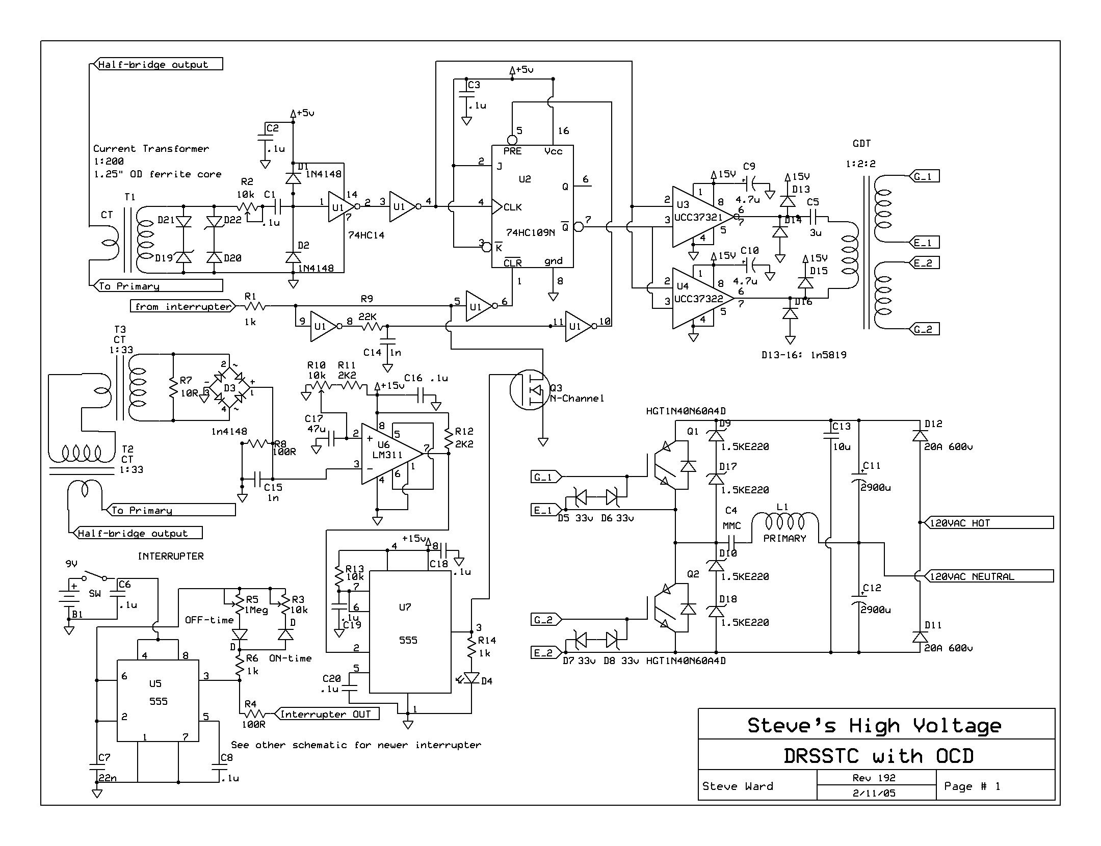
Can you kindly assist me to start as safe as possible (don't damage components of UD 2.5) and give advice (or maybe there's a checklist) how to check that UD 2.5 assembled fine?
Re: Universal DRSSTC Driver V2.5 (Sold Out)
jay, Thu Oct 09 2014, 12:53AM
Eric,
I'd like to buy 1 of your boards, if you still have any left.
Thank You
jay, Thu Oct 09 2014, 12:53AM
Eric,
I'd like to buy 1 of your boards, if you still have any left.
Thank You
Re: Universal DRSSTC Driver V2.5 (Sold Out)
Graham Armitage, Wed Dec 24 2014, 03:15PM
I am testing a UD2.5A board that I just completed. voltage rails all looked good. I have D13 removed as I am not using the IF receiver. Added in the R21 resistor and now the OCD LED comes on. Before adding R21 it did not. Looking at the circuit, I don't see why it would come on without any OCD current. Anyone else seen this?
Re: Universal DRSSTC Driver V2.5 (Sold Out)
loneoceans, Wed Dec 24 2014, 06:23PM
It's normal for the OCD light to turn on during startup (is this what you meant?) This is just the behavior of the 74HC74 flipflop starting in that state. I actually use it as a good indicator if my interrupter line is working by sending a pulse which should clear it when triggered.
Re: Universal DRSSTC Driver V2.5 (Sold Out)
Graham Armitage, Fri Dec 26 2014, 03:38AM
Yes - that is what I mean. When starting up with no FB or OCD signals the OCD LED comes on. If this is normal, then I will proceed with testing.
Thanks a bunch.
Graham Armitage, Fri Dec 26 2014, 03:38AM
Yes - that is what I mean. When starting up with no FB or OCD signals the OCD LED comes on. If this is normal, then I will proceed with testing.
Thanks a bunch.
Re: Universal DRSSTC Driver V2.5 (Sold Out)
Vitalii, Mon Feb 09 2015, 10:34AM
Hi!
Third time burned FDD8424H (U3 on the board).
So what I do:
I power the driver from DC-source - 6S LiPo battery (25.2V but 24 with load). I removed B1 rectifier (to prevent 0.7 voltage drop on it).
When I power on the driver from 12V - it works as expected.
But 24V power source burns U3 each time when I try to power it on. I tested with GDT connected and disconnected - usually the same result. (but there's no shorts on the board, I checked at least 5 times).
I'm not sure about U1 and U2, because they are not installed.
But U4 doesn't burn!!
I checked FDD8424H datasheet - it can work up to 40V.
Please give me an advice how to solve the problem?
Re: Universal DRSSTC Driver V2.5 (Sold Out)
hen918, Mon Feb 09 2015, 07:27PM
sorry, I haven't looked at the schematics, but couldn't it be some inductive element causing high(er) voltage back EMF?
hen918, Mon Feb 09 2015, 07:27PM
Vitalii wrote ...
Hi!
Third time burned FDD8424H (U3 on the board).
So what I do:
I power the driver from DC-source - 6S LiPo battery (25.2V but 24 with load). I removed B1 rectifier (to prevent 0.7 voltage drop on it).
When I power on the driver from 12V - it works as expected.
But 24V power source burns U3 each time when I try to power it on. I tested with GDT connected and disconnected - usually the same result. (but there's no shorts on the board, I checked at least 5 times).
I'm not sure about U1 and U2, because they are not installed.
But U4 doesn't burn!!
I checked FDD8424H datasheet - it can work up to 40V.
Please give me an advice how to solve the problem?
sorry, I haven't looked at the schematics, but couldn't it be some inductive element causing high(er) voltage back EMF?
Re: Universal DRSSTC Driver V2.5 (Sold Out)
Vitalii, Tue Feb 10 2015, 04:25PM
ok. I found a real cause of this stupid issue.
It's a problem with board tracing. I'm not sure where's the mistake but it can be in Gerber-files. In other case it's a mistake that happened on board printing machine.
2 lanes on the board that connect U1 and U3 sources to R12 and R22 were not connected. As a result one of gates had 22V.
Signal on U1 Gate1:

Signal on U1 Gate2:

Error on the board (marked pink):
I add all this data to tread because somebody may have similar behavior - Driver works fine on 12 V but burns on 24V.
Now it works fine from 25V source without B1 rectifier!
Vitalii, Tue Feb 10 2015, 04:25PM
ok. I found a real cause of this stupid issue.
It's a problem with board tracing. I'm not sure where's the mistake but it can be in Gerber-files. In other case it's a mistake that happened on board printing machine.
2 lanes on the board that connect U1 and U3 sources to R12 and R22 were not connected. As a result one of gates had 22V.
Signal on U1 Gate1:
Signal on U1 Gate2:
Error on the board (marked pink):

I add all this data to tread because somebody may have similar behavior - Driver works fine on 12 V but burns on 24V.
Now it works fine from 25V source without B1 rectifier!
Re: Universal DRSSTC Driver V2.5 (Sold Out)
Aragorn, Wed Feb 14 2018, 02:47PM
Anyone got a mirror of the board files/schematics etc for the UD2.5 board that were originally hosted on Erics Google Drive?
The link on the blog is dead.
Aragorn, Wed Feb 14 2018, 02:47PM
Anyone got a mirror of the board files/schematics etc for the UD2.5 board that were originally hosted on Erics Google Drive?
The link on the blog is dead.
Re: Universal DRSSTC Driver V2.5 (Sold Out)
Hydron, Thu Feb 15 2018, 11:19AM
I may have them somewhere but would probably have to dig around to find them. Any reason why you need them specifically? If you're building a new controller I'd suggest starting with Philip Slawinski's UD+, which is more advanced and is also open-source (though the PCB is in Altium format).
Re: Universal DRSSTC Driver V2.5 (Sold Out)
Aragorn, Thu Feb 15 2018, 02:36PM
I have some PCB's here which i had made back when this board was new, dug them out the other night and realised all the info about them had vanished.
Is the new UD+ better by enough that i should bin what i have and start again?
Aragorn, Thu Feb 15 2018, 02:36PM
I have some PCB's here which i had made back when this board was new, dug them out the other night and realised all the info about them had vanished.
Is the new UD+ better by enough that i should bin what i have and start again?
Re: Universal DRSSTC Driver V2.5 (Sold Out)
Hydron, Thu Feb 15 2018, 05:52PM
If you've already got a populated board then UD2.5 will be fine for a standard DRSSTC without freewheeling or other advanced features.
I think I found the UD2.5 eagle files (I don't have eagle installed I cant open them) so I've attached them here.
Hydron, Thu Feb 15 2018, 05:52PM
If you've already got a populated board then UD2.5 will be fine for a standard DRSSTC without freewheeling or other advanced features.
I think I found the UD2.5 eagle files (I don't have eagle installed I cant open them) so I've attached them here.
Re: Universal DRSSTC Driver V2.5 (Sold Out)
Hydron, Thu Feb 15 2018, 05:55PM
...and I've had to double post as the upload didn't work and you can't add attachments to existing posts in edit mode. See attached .zip.
]ud2_5_revb.zip[/file]
Hydron, Thu Feb 15 2018, 05:55PM
...and I've had to double post as the upload didn't work and you can't add attachments to existing posts in edit mode. See attached .zip.
]ud2_5_revb.zip[/file]
Re: Universal DRSSTC Driver V2.5 (Sold Out)
Aragorn, Thu Feb 15 2018, 08:03PM
Thanks. I seem to have found a printed copy of the BOM and schematic. Looking over my boards they appear to be revision 0.
Hopefully i've got enough to go on to get them finished and working.
One board is mostly assembled, and i've got a pile of parts for a second one as a spare/incase i blow it up etc.
Just need to find some time to bring it all together!
Print this page