
Bridge rectifier circuit
Andre, Wed Jan 30 2013, 04:24PMdoes anyone seen this type of rectifier circuit before? do you know how is wire?

Re: Bridge rectifier circuit
Meatball, Wed Jan 30 2013, 11:16PM
It looks like a voltage multiplier.. a very fancy rectifier.
Meatball, Wed Jan 30 2013, 11:16PM
It looks like a voltage multiplier.. a very fancy rectifier.
Re: Bridge rectifier circuit
Andre, Wed Jan 30 2013, 11:39PM
Andre, Wed Jan 30 2013, 11:39PM
Meatball wrote ...
It looks like a voltage multiplier.. a very fancy rectifier.
is not a voltage multiplier, look it has 3 transformer connected to this half bridge rectifier, trying to figure out how. the 3 transformers are connected together with the diodes and caps.It looks like a voltage multiplier.. a very fancy rectifier.
Re: Bridge rectifier circuit
Electroholic, Thu Jan 31 2013, 01:18AM
Similar to a diode split flyback maybe?
Electroholic, Thu Jan 31 2013, 01:18AM
Similar to a diode split flyback maybe?
Re: Bridge rectifier circuit
klugesmith, Thu Jan 31 2013, 07:43AM
I will hazard a guess.
But first: Apparently the Israeli seller in your link bought the transformer just a few days ago, from a prolific Wisconsinite ebay seller called goodgadgets2u. And is now using the exact same pictures and description.

Now it just so happens that I recently bought one myself, but have not had time to trace the circuit. In how much of a hurry are you? Will anyone else here own up to having bought one?
Here is my guess. Each of the three HV coils develops +/- 12.5 kV, and feeds a voltage doubler (2 diodes & 2 capacitors):
The ferrite core is like none I've seen before. 2 identical parts, and the round leg that goes through the coil bobbins is hollow. Seller "g" said that's to allow oil convection to cool the core. The item came wrapped in oil-soaked newspaper, inside a couple of nested plastic bags.
klugesmith, Thu Jan 31 2013, 07:43AM
I will hazard a guess.
But first: Apparently the Israeli seller in your link bought the transformer just a few days ago, from a prolific Wisconsinite ebay seller called goodgadgets2u. And is now using the exact same pictures and description.

Now it just so happens that I recently bought one myself, but have not had time to trace the circuit. In how much of a hurry are you? Will anyone else here own up to having bought one?
Here is my guess. Each of the three HV coils develops +/- 12.5 kV, and feeds a voltage doubler (2 diodes & 2 capacitors):
+-->|----+-->|--+
 |  D1    |  D2  |
 |     coil      |
 |     |         |
-+--||-+-----||--+-
    C1       C2
The three voltage doublers are in series for 75 kV total. The ferrite core is like none I've seen before. 2 identical parts, and the round leg that goes through the coil bobbins is hollow. Seller "g" said that's to allow oil convection to cool the core. The item came wrapped in oil-soaked newspaper, inside a couple of nested plastic bags.
Re: Bridge rectifier circuit
Andre, Thu Jan 31 2013, 03:27PM
[quote]
Here is my guess. Each of the three HV coils develops +/- 12.5 kV, and feeds a voltage doubler (2 diodes & 2 capacitors):
The ferrite core is like none I've seen before. 2 identical parts, and the round leg that goes through the coil bobbins is hollow. Seller "g" said that's to allow oil convection to cool the core. The item came wrapped in oil-soaked newspaper, inside a couple of nested plastic bags.
[/quote1359645945]
First congratulations on your 1000's post, :)
and thats very usefull information, I will try that circuit today, I was confused do I need D1 and C1 if the outputs comes from D2 and C2? if thats how they are connected we would only need 3 caps and 3 diodes?
can you share more pictures of it? I'm trying to replicate the design,
Thank you again!!!!!!!!!!
Andre, Thu Jan 31 2013, 03:27PM
[quote]
Here is my guess. Each of the three HV coils develops +/- 12.5 kV, and feeds a voltage doubler (2 diodes & 2 capacitors):
+-->|----+-->|--+
 |  D1    |  D2  |
 |     coil      |
 |     |         |
-+--||-+-----||--+-
    C1       C2
The three voltage doublers are in series for 75 kV total. The ferrite core is like none I've seen before. 2 identical parts, and the round leg that goes through the coil bobbins is hollow. Seller "g" said that's to allow oil convection to cool the core. The item came wrapped in oil-soaked newspaper, inside a couple of nested plastic bags.
[/quote1359645945]
First congratulations on your 1000's post, :)
and thats very usefull information, I will try that circuit today, I was confused do I need D1 and C1 if the outputs comes from D2 and C2? if thats how they are connected we would only need 3 caps and 3 diodes?
can you share more pictures of it? I'm trying to replicate the design,
Thank you again!!!!!!!!!!
Re: Bridge rectifier circuit
klugesmith, Fri Feb 01 2013, 06:03AM
Thank you (about #1000; I would not have noticed).
Re. the symmetrical voltage doubler circuit, perhaps you don't get it. What I drew charges both capacitors to the same voltage, but the positive end of C1 is common with the negative end of C2.
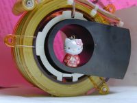
I still don't know how the transformer in OP is wired. To save me some trouble, please study these pictures and draw us a schematic. Anyone else is welcome to do the same.
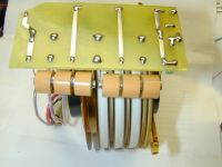
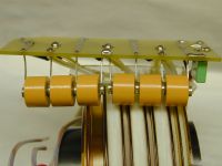
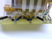
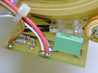


Re: Bridge rectifier circuit
Andre, Fri Feb 01 2013, 04:38PM
from the pictures I came out with this, is a bit confusing how it adds up the voltage, and how can it outputs anything like that, it seems to be a short.

Andre, Fri Feb 01 2013, 04:38PM
from the pictures I came out with this, is a bit confusing how it adds up the voltage, and how can it outputs anything like that, it seems to be a short.

Re: Bridge rectifier circuit
klugesmith, Sat Feb 02 2013, 12:55AM
Thanks, Ash. Guess I'll carry on here for now.
Thanks, Andre, for the schematic.
I think readers might overlook this thread because of its mundane title. Would you mind editing the title of original post to something like "Voltage Multiplier on HF XRT ? " ?
I think there is a wire missing from the left end of pictures and schematic, which I claim is the positive output from a series of three voltage doublers. And that all the wires at the right end are the negative output, I bet associated with a Coolidge tube cathode and grid.
Not shown is any filament winding, which might have once been in the empty large-diameter bobbin.
I'll bet the capacitors are not there for resonance. Without load, each of them will charge to a DC level equal to peak voltage of one coil. Each with positive on the left and negative on the right. The phasing of the three HV coils does not matter.
Re: Bridge rectifier circuit
Ash Small, Sat Feb 02 2013, 02:10PM
You are most likely correct. As there was no evidence of the 'missing wire', I was trying to suggest an alternative, but there probably is a wire missing. As all the wires are joined at the right hand end, it would be reasonable to assume they are all at the same polarity,
I do, however, still suspect that this is likely to work best at resonance, with a constant load, I'd suspect that power output is controlled by regulating voltage/current to the primaries. I also still suspect that it is driven in flyback mode, in order to achieve the voltages required. However, these are only suspicions based upon what I've been reading about regarding TV flybacks operating at resonance.
Print this page