
Class E Troubles
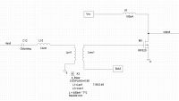
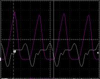
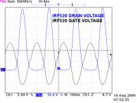
HV Enthusiast, Wed Aug 16 2006, 05:43PMI'm helping a friend of mine build a Class E tesla coil and have been experiencing some troubles which i'm not sure how to fix at this point. This is looking at a drive stage (see photo below) and the gate (white) and drain (purple) waveforms. Looks like the falling edge of the gate is doing what it is supposed to be, but the rising edge is doing some funky stuff - looks like miller plateau stuff going on there . . .
Anyone have some ideas on how to "clean" this up?
The circuit is a basic transformer fed gate drive arrangement where the circuit is tuned so that the series inductance (including leakage inductance of transformer) cancels out capacitive reactance of mosfet gate, and the transformer is used primarily to match the low input impedance of the gate to that of my output stage.
Re: Class E Troubles
Steve Ward, Wed Aug 16 2006, 05:58PM
Maybe adding a discrete capacitor across the gate would help shape it up, of course you would need a different leakage inductance to resonate with. My thought here is that it would simply increase the available current, to push past the miller effect quicker than it is.
Also, looking at the actual sinusoid parts of the gate waveform, it looks like your LC on the output (driving the coil) is not matched with the natural Fo of the gate circuitry (the gate seems to be tuned too high).
Re: Class E Troubles
Hazmatt_(The Underdog), Wed Aug 16 2006, 07:17PM
I'm not really sure what you want as a waveform, but I'll give it a shot anywho.
For the Gate pulse I would put a zener on the gate to flatten out the signal, which would give you more of a pulse. And possibly a resistor in series with the zener to set the 'depth' of the clamping.
Re: Class E Troubles
Marko, Wed Aug 16 2006, 07:59PM
Zener is unneeded when resonant drive is set correctly (altough they can serve as a protection).
I think he just needs to adjust Lsec1 in resonance with gate as Steve already explained.
IRF520 has much lower gate capacitance than IRFP450 or 114N50 (used in Richie Burnett's output stage) so the transformer is going to need a bit twiddling with number of transformer turns and coupling.
Maybe a variable choke in series with secondary could help with adjustment..
Re: Class E Troubles
Terry Fritz, Wed Aug 16 2006, 10:43PM
Hi,
You probably won't clean it up much. Lower drive impedance...
Might see this patent:
USPTO # 05187580
The driver (#29) is another class E power driver, but just a conventional Nat Sokal thing...
But TC frequencies are far lower... So maybe you can do it. Be sure L8 is a really good inductor and is not saturating.
Cheers,
Terry
Re: Class E Troubles
ragnar, Wed Aug 16 2006, 11:38PM
If the shunt capacitor is ringing too low (i.e. causing the body diode to conduct), you'll get ringing and ripples appearing on the gatedrive.
Similarly if the shunt capacitor is partially discharging into the MOSFET channel, you'll get spikies on the gate waveform at that point.
Have you tried tuning the drive frequency?
If you can afford to add more inductance to the circuit (might need to take some turns off the GDT to allow this), use a few turns of wire a round your finger, and squeeze or stretch it as appropriate until you get the maximum rise.
Just curious, who's your friend and what frequency are we talking here?
What does the gate waveform look like with no power applied? You probably want him ringing up to at _least_ +/- 20V without power, which will be damped to ~ +/- 12 to 15V when you let drain current flow.
You might also find it easier to put your primary where that RF choke is (straight between positive/drain). Means you have to retune less stuff when twiddling.
ragnar, Wed Aug 16 2006, 11:38PM
If the shunt capacitor is ringing too low (i.e. causing the body diode to conduct), you'll get ringing and ripples appearing on the gatedrive.
Similarly if the shunt capacitor is partially discharging into the MOSFET channel, you'll get spikies on the gate waveform at that point.
Have you tried tuning the drive frequency?
If you can afford to add more inductance to the circuit (might need to take some turns off the GDT to allow this), use a few turns of wire a round your finger, and squeeze or stretch it as appropriate until you get the maximum rise.
Just curious, who's your friend and what frequency are we talking here?

What does the gate waveform look like with no power applied? You probably want him ringing up to at _least_ +/- 20V without power, which will be damped to ~ +/- 12 to 15V when you let drain current flow.
You might also find it easier to put your primary where that RF choke is (straight between positive/drain). Means you have to retune less stuff when twiddling.
Re: Class E Troubles
Steve Conner, Thu Aug 17 2006, 09:25AM
I think it's weirdness caused by the non-linearity of the device capacitances. The gate and Miller capacitances are both very strongly dependent on Vgs and Vgd, and they are part of your resonant gate circuit.
The fact that you have a f/2 subharmonic in the output tends to suggest that explanation too. If I remember right, the cure is to add damping with a resistor in the gate circuit, and/or to put a capacitor from gate to ground to swamp the non-linear capacitance.
*edit* I thought about it some more and this is completely the wrong explanation for the problem.

Re: Class E Troubles
Marko, Thu Aug 17 2006, 12:03PM
Well putting a resistor in series with gate isn't a bad idea at all.
It can help regulating Q of the circuit in order not to overvolt the mosfet (easier than adjusting external power).
Marko, Thu Aug 17 2006, 12:03PM
Steve Conner wrote ...


Well putting a resistor in series with gate isn't a bad idea at all.
It can help regulating Q of the circuit in order not to overvolt the mosfet (easier than adjusting external power).
Re: Class E Troubles
HV Enthusiast, Thu Aug 17 2006, 01:33PM
The impedance transformer is what accomplishes this. Although its primary purpose is to transform the very low gate resistance of the IRF520 to match the output impedance of the input stage, it also acts like a series impedance to the gate. Remember, at these frequencies, we need to look at the circuit in an "RF" sense as opposed to traditional circuit theory.
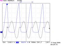
We worked on the circuit a bit more last night and found that the drain choke on the IRF520 was corrupting the waveform. The drain choke was originally a 25 turn choke around a 0.25" x 1.00" DIA Type 77 material ferrite rod. With the ferrite rod core inserted in the coil, the waveform had that first notch in it (See attached image)
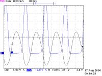
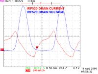
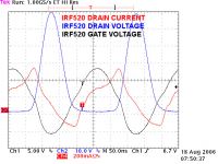
Now, removing the core, the waveforms cleaned up significantly and its working pretty good (IRF520 barely gets warm to the touch now)
(see attached image)
I also had to adjust the impedance matching transformer and the series tuning inductor to get a good amplitude on the gate (about 12V peak)
Dan
HV Enthusiast, Thu Aug 17 2006, 01:33PM
wrote ...
Well putting a resistor in series with gate isn't a bad idea at all.
It can help regulating Q of the circuit in order not to overvolt the mosfet (easier than adjusting external power).
Well putting a resistor in series with gate isn't a bad idea at all.
It can help regulating Q of the circuit in order not to overvolt the mosfet (easier than adjusting external power).
The impedance transformer is what accomplishes this. Although its primary purpose is to transform the very low gate resistance of the IRF520 to match the output impedance of the input stage, it also acts like a series impedance to the gate. Remember, at these frequencies, we need to look at the circuit in an "RF" sense as opposed to traditional circuit theory.
We worked on the circuit a bit more last night and found that the drain choke on the IRF520 was corrupting the waveform. The drain choke was originally a 25 turn choke around a 0.25" x 1.00" DIA Type 77 material ferrite rod. With the ferrite rod core inserted in the coil, the waveform had that first notch in it (See attached image)
Now, removing the core, the waveforms cleaned up significantly and its working pretty good (IRF520 barely gets warm to the touch now)
(see attached image)
I also had to adjust the impedance matching transformer and the series tuning inductor to get a good amplitude on the gate (about 12V peak)
Dan


Re: Class E Troubles
ragnar, Thu Aug 17 2006, 11:30PM
IRF520, eh? This must be some high frequency coil, EVR.
ragnar, Thu Aug 17 2006, 11:30PM
IRF520, eh? This must be some high frequency coil, EVR.
Re: Class E Troubles
HV Enthusiast, Fri Aug 18 2006, 12:09AM
Just a measely 4MHz. . .
HV Enthusiast, Fri Aug 18 2006, 12:09AM
Just a measely 4MHz. . .
Re: Class E Troubles
ragnar, Fri Aug 18 2006, 01:33AM
If you can get it all tuned nicely, the IRF520 will allow for 24V supply with a little overhead. Mmm, portable.
Did I tell you about my idea for plasma-speaker earbud-headphones? =P
ragnar, Fri Aug 18 2006, 01:33AM
If you can get it all tuned nicely, the IRF520 will allow for 24V supply with a little overhead. Mmm, portable.
Did I tell you about my idea for plasma-speaker earbud-headphones? =P
Re: Class E Troubles
Wilson, Fri Aug 18 2006, 01:40AM
I don't think anyone would want 2000+ degree plasma and high voltage on the sides of their heads BP lol
lol
Is the coil going to be audio modulated EVR?
Wilson, Fri Aug 18 2006, 01:40AM
I don't think anyone would want 2000+ degree plasma and high voltage on the sides of their heads BP
 lol
lolIs the coil going to be audio modulated EVR?
Re: Class E Troubles
HV Enthusiast, Fri Aug 18 2006, 12:09PM
Here are the latest plots we took this morning of the IRF520 driver stage. Looks good now and the IRF520 isn't even warm to touch when driving the high power stage.
HV Enthusiast, Fri Aug 18 2006, 12:09PM
Here are the latest plots we took this morning of the IRF520 driver stage. Looks good now and the IRF520 isn't even warm to touch when driving the high power stage.


Re: Class E Troubles
ragnar, Fri Aug 18 2006, 12:54PM
Very nice, looking forward to seeing the sparks =-)
ragnar, Fri Aug 18 2006, 12:54PM
Very nice, looking forward to seeing the sparks =-)
Re: Class E Troubles
Marko, Fri Aug 18 2006, 04:10PM
As I figured out for now this shown circuit is a driver for another high-power mosfet in class E.
CIrcuit seems to closely resemble richieburnett's class E coil.
Marko, Fri Aug 18 2006, 04:10PM
blackplasma wrote ...
If you can get it all tuned nicely, the IRF520 will allow for 24V supply with a little overhead. Mmm, portable.
Did I tell you about my idea for plasma-speaker earbud-headphones? =P
If you can get it all tuned nicely, the IRF520 will allow for 24V supply with a little overhead. Mmm, portable.
Did I tell you about my idea for plasma-speaker earbud-headphones? =P
As I figured out for now this shown circuit is a driver for another high-power mosfet in class E.
CIrcuit seems to closely resemble richieburnett's class E coil.
Re: Class E Troubles
HV Enthusiast, Mon Aug 21 2006, 12:45PM
Having some more fun with the coil this morning.
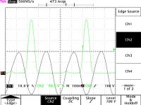
Got the final power stage running and have a weird problem . . . Seems the drain waveform looks class E, but is only turning off every other
waveform, even though the gate looks pretty solid.
Any ideas? (scratching my head . . .)

Re: Class E Troubles
Marko, Mon Aug 21 2006, 12:57PM
I get that if I tune LC to harmonic and overcouple. (but this may not be the same since my circuit was somewhat different from richie b.)
Class E stuff usually just needs a ton of tuning and twiddling until everything settls up.
Marko, Mon Aug 21 2006, 12:57PM
I get that if I tune LC to harmonic and overcouple. (but this may not be the same since my circuit was somewhat different from richie b.)
Class E stuff usually just needs a ton of tuning and twiddling until everything settls up.
Re: Class E Troubles
ragnar, Mon Aug 21 2006, 01:06PM
You'll find just changing the frequency minutely may be sufficient to fix this.
IIRC you may need to _increase_ the frequency to rectify this... and if that's going to fix it, you'll find a sweet/sensitive spot at which you get the correct count of peaks appearing.
Try adding a little more(--?) capacitance to the shunt, whilst also twiddling that frequency ever so slightly. Try lowering the coupling a little, too.
Print this page