V3 Coil Carbine
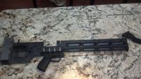
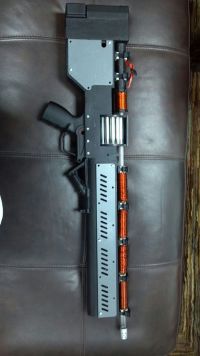
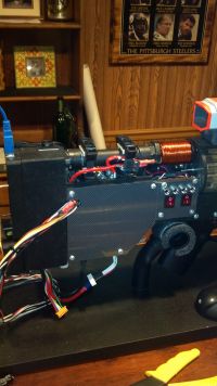
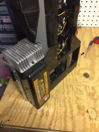
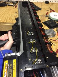
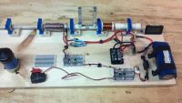
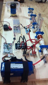
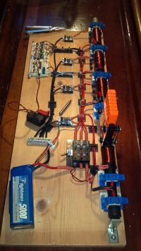
ben5017, Fri Nov 30 2012, 03:25AMAfter my proof of concept S.C.A.R. 1000 project, I have been lurking around the forum and have slowly been making progress on the upgraded model. I decided to lay out an experimental benchtop version to finetune the design before I complete the V3CC portable version.
Project Goals of X3CC:
-To create an easily modified experimental testing rig as a stepping stone for the final version (V3CC)
-Learn to optomize a multi-stage coil gun.
Future design Vision of V3CC:
-A 6s Lipo powered, 4+1 stage, select fire, drum fed, portable coilgun
Project Goals of VC33:
-Rate of Fire: 150 rpm
-Velocity: 50 m/s
-Efficency: 8-10%
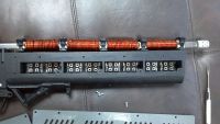
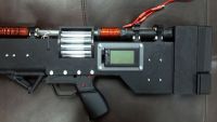
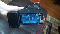
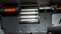
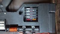
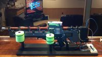
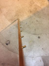
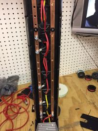
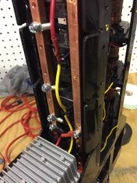
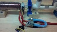
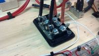
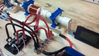
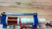
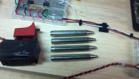
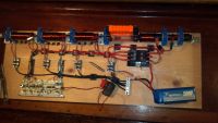
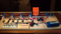
The pictures attached show my progress to date, as well as a picture of the completed S.C.A.R 1000.
Progress:
-Injector is completed and operational.
-Optical Sensor is Completed and operational.
-Stage 1 Completed
Re: V3 Coil Carbine
PSCG, Fri Nov 30 2012, 03:41PM
Good to see you with a new built! Are you using the design that Saz43 follows with his own multistage coilgun?
PSCG, Fri Nov 30 2012, 03:41PM
Good to see you with a new built! Are you using the design that Saz43 follows with his own multistage coilgun?
Re: V3 Coil Carbine
ben5017, Fri Nov 30 2012, 03:56PM
PSCG:
Saz has deffinatly given me some motivation to keep making progress, and my design is somewhat similar. However there are some major diffrences.
1. It will be ran off of 6s instead of 12s
2. It will have a cap bank to increase the discharge rate as opposed to running it just off of the lipo. Hopefully it will give it some more punch.
3. It uses an "injector" to smack the projectile out of the magazine, as opposed to having the 1st stage pull the projectile out of the clip
4. It will be a 4+1 coilgun (4 stages + Injector) as opposed to 8 smaller stages
Re: V3 Coil Carbine
PSCG, Sat Dec 01 2012, 09:10AM
Very interesting changes. I'd like to see how the "battery - capacitor bank" combination will work.
PSCG, Sat Dec 01 2012, 09:10AM
Very interesting changes. I'd like to see how the "battery - capacitor bank" combination will work.
Re: V3 Coil Carbine
Yandersen, Mon Dec 03 2012, 08:15AM
Ben, you asked me to enlight my design of recuperational gauss technology, but your current battery-driven design is completely incompatible with it. See, the keypoint of mine is using non-polar caps as power source for the coils. If you are going to start from scratch, let me know. By now, my 6-stage gun shows average efficiency 20.6% (recuperation is taken into account) by accelerating 6.57gramm projectile of 9.4mm caliber to the speed 54m/s while initial energy stored in 3 caps is just 55J. If such perspective will initiate you to try my technology, I'll tell in details how you can build one.
Re: V3 Coil Carbine
ben5017, Mon Dec 03 2012, 06:26PM
Yandersen,
To clarify, I am still at the beginning stages of this build, and moreover its entire purpose is as a research and testing platform for later builds. I most definatly want to experiment with your design, with modifications of course (neither of us would get much out of simply duplicating your work).
To your point. I kind of figured that it would not be compatible with a battery driven gun. However I am still interested in seeing if it can be used to capture the leftover energy in my coil and the dissipate it elsewhere after the coil shuts off. I realize that this would not allow me to reuse the captured energy in additional stages, but i am thinking it would still be more effective way to minimize suck back, compared to an anti-parallel diode, and still have the rapid rate of fire I am looking for.
Thoughts?
Re: V3 Coil Carbine
Yandersen, Mon Dec 03 2012, 06:44PM
Easy. Just put a couple of high power zener diodes in series with dempher diode. When coil disconnected from the power source, the speed of energy dissipation will be proportional to the voltage spike over the coil. Choose the highest possible voltage your commutation elements can handle.
To determine the voltage spike' magnitude check the peak current in a coil. Multiply this value by coil resistance, add 1V for dempher diode and around 1.5 values of zener diode voltage rating. Make sure zener can handle the spike current for a time it will run (this characteristics are rarely shown in the datasheet, howhether). I think, couple of 5W zener in parallel will handle the spike. To be sure, put 5 or so of them in parallel and check the voltage over them during the spike. If it is just 1-2 Volts over their rating, you don't need that much - remove some and check again. Zener diode, when burned with moderate overwhelming, become a shunt resistor with few ohms of resistance, so don't be worry much about the rest of the circuit.
Re: V3 Coil Carbine
ben5017, Mon Dec 03 2012, 07:31PM
Is this setup worth pursuing since it wont be able to use the captured energy, and therefore could not give me the same magnitude of efficiency gains you achieved? It should still give me a good boost in velocity due to almost eliminating suck back true? Can you give me a reasonable guess of % increase in velocity I can expect?
What if I were to charge nonpolar caps directly off of the lipos and use it to fire the coils?, could it then recoup and use the energy if I gave the batteries some sort of protection so they couldn’t see the reverse voltage, kind of like a hybrid between a cap bank and direct lipo driven coils gun
Re: V3 Coil Carbine
Yandersen, Mon Dec 03 2012, 07:57PM
Well, eliminating suckback may give you up to 10-20% of efficiency in total, while recuperation will not increase bullet's energy but doubles efficiency by reusing energy leftovers. If you would wire your coils in a proper shape (length is equal to the inner diameter, 3x outer diameter to inner), use the shortest possible projectile and add external iron (at least washers at the ends of a coils), then you can be totally sure about those numbers. But by now, just put zeners in series with your dempher diode and see the difference.
Re: V3 Coil Carbine
ben5017, Mon Dec 03 2012, 08:12PM
what do you think about my proposed "hybrid" setup
ben5017, Mon Dec 03 2012, 08:12PM
what do you think about my proposed "hybrid" setup
Re: V3 Coil Carbine
Yandersen, Mon Dec 03 2012, 10:45PM
Without knowing any of the technical parameters? Nothing. :)
You mean cap in parallel with the battery, in general? Just try with and without a cap and see the difference. Better to have a battery that can give the desired current so to not waste mass on cap. But if battery is weak, then you can assume your coilgun is driven from the cap - in this case you need a really big one, with low ESR and, preferably, low ESL too. Strong battery doesn't require cap helper, while weak battery need a big cap which can store multiple of energy consumed by coils. If your battery alone can push few hundreds of amps into your coils, then I don't think that cap will do much difference. But if your battery can't give the crank current you need, then your gun operate from cap and it would be better to add a charger. No rapid fire in this case, of course.
Re: V3 Coil Carbine
ben5017, Tue Dec 04 2012, 03:07AM
My Lipos will be more than enough to drive the coil. I am talking about using a parallel non polar cap bank so that i can capture the energy that would be wasted, while still driving it from the battery
ben5017, Tue Dec 04 2012, 03:07AM
My Lipos will be more than enough to drive the coil. I am talking about using a parallel non polar cap bank so that i can capture the energy that would be wasted, while still driving it from the battery
Re: V3 Coil Carbine
Yandersen, Tue Dec 04 2012, 03:56AM
Well, maybe you will recuperate few joules of energy. Will it be enough to drive another coil? I think, forget about the caps in your design. When you discharge cap onto coil, pulse time is predetermined. Your system uses optical triggering, so here is another incompatibility. Mine has no any sensors - each subsequent stage shots immidiately after previous one is done discharging back to it's cap. Pulse time differs due to inductance which is smaller for each subsequent stage. So my gauss has no feedback. And recuperation is relatively small, actually - less than half of energy used returns back to cap. See the table (7th and 8th stages are not done):

Oh, and take into account that cap is repolarized when first coil discharges onto it.
Yandersen, Tue Dec 04 2012, 03:56AM
Well, maybe you will recuperate few joules of energy. Will it be enough to drive another coil? I think, forget about the caps in your design. When you discharge cap onto coil, pulse time is predetermined. Your system uses optical triggering, so here is another incompatibility. Mine has no any sensors - each subsequent stage shots immidiately after previous one is done discharging back to it's cap. Pulse time differs due to inductance which is smaller for each subsequent stage. So my gauss has no feedback. And recuperation is relatively small, actually - less than half of energy used returns back to cap. See the table (7th and 8th stages are not done):

Oh, and take into account that cap is repolarized when first coil discharges onto it.
Re: V3 Coil Carbine
Steve Conner, Tue Dec 04 2012, 10:21AM
The best way I know of recovering energy is using the diagonal half-bridge. It is expensive in components as it needs two IGBTs, two diodes and one high-side gate drive.
Using non-polar capacitors is all very well, but they will be left charged with the wrong polarity for the next shot.
Re: V3 Coil Carbine
ben5017, Tue Dec 04 2012, 04:37PM
Steve,
I am more interested in eliminating suck back as completely as possible to increase velocity, and not as concerned with reusing the energy to gain efficiency. That being said would an h-bridge be as effective of removing leftover coil energy as absorbing it with a non polar cap bank would be?
Re: V3 Coil Carbine
Steve Conner, Tue Dec 04 2012, 05:10PM
Probably about the same. In theory the non-polar capbank will give a half sine wave of current, the H-bridge gives a triangular pulse.
Steve Conner, Tue Dec 04 2012, 05:10PM
Probably about the same. In theory the non-polar capbank will give a half sine wave of current, the H-bridge gives a triangular pulse.
Re: V3 Coil Carbine
ben5017, Tue Dec 04 2012, 06:15PM
Ok, sounds to me that non-polar caps would be a much simpler and cheaper solution to limit suck back, if energy recuperation was not a factor.
Would the H-Bridge make it possible to recoup energy into a capacitor bank in parallel with my batteries? Or would the caps be "full" with no capacitance left to take in the recouped energy since it would always be connected to my battery and therefore always “topped offâ€.
Re: V3 Coil Carbine
Ash Small, Tue Dec 04 2012, 07:32PM
How about disconnecting the battery before firing, then, after firing, re-connect, but with reversed polarity, so that the battery 'tops up' the capacitor, then disconnect and fire again (still with reverse polarity,), then re-connect the battery as it was originally connected, and repeat.....
I know it sounds complicated, but it would only take a handful of 'fets and a chip to switch them.
Re: V3 Coil Carbine
Steve Conner, Tue Dec 04 2012, 08:48PM
Yes, but the same "handful of fets and chip" could be used to implement the diagonal half-bridge. The fets might need to be bigger since they carry the firing current, but regular electrolytics are so much cheaper per joule than non-polar capacitors, you probably still win.
The half-bridge circuit dumps the energy back into the DC bus. If you have a capacitor in parallel with your battery, you can view the recovered energy as recharging the capacitor a little bit, but mostly recharging the battery.
Steve Conner, Tue Dec 04 2012, 08:48PM
Yes, but the same "handful of fets and chip" could be used to implement the diagonal half-bridge.
 The fets might need to be bigger since they carry the firing current, but regular electrolytics are so much cheaper per joule than non-polar capacitors, you probably still win.
The half-bridge circuit dumps the energy back into the DC bus. If you have a capacitor in parallel with your battery, you can view the recovered energy as recharging the capacitor a little bit, but mostly recharging the battery.
Re: V3 Coil Carbine
Yandersen, Wed Dec 05 2012, 12:07AM
Steve, when non-polar caps used, two coils operate from one cap: first coil inverses cap's polarity once, second coil reverses it back. So there are no waste at all - whatever left from two stages is left in cap so charging it next time is easier. All you need is to disconnect the charger before firing so it will not be damaged when cap's polarity temporarily inversed by even-numbered coils.
Ben, burning leftover energy on zeners is the fastest possible way of energy dump. And the higher the voltage, the faster energy will dissipate. It is even faster than dump it onto cap. This way suckback will be eliminated - guaranteed. And all you need is a couple of paralleled high power zeners in series with your dempher diode.
Re: V3 Coil Carbine
Saz43, Wed Dec 05 2012, 04:10PM
Keep in mind that the half bridge will dump close to peak coil current back into the battery (100's of amps), which is probably not very good since LiPos typically have a 1C charge rate. Although it will only be for a millisecond or so, so maybe it's not a big deal. Adding a capacitor in parallel to the battery makes little difference in terms of energy recovery.
Saz43, Wed Dec 05 2012, 04:10PM
Steve Conner wrote ...
The half-bridge circuit dumps the energy back into the DC bus. If you have a capacitor in parallel with your battery, you can view the recovered energy as recharging the capacitor a little bit, but mostly recharging the battery.
The half-bridge circuit dumps the energy back into the DC bus. If you have a capacitor in parallel with your battery, you can view the recovered energy as recharging the capacitor a little bit, but mostly recharging the battery.
Keep in mind that the half bridge will dump close to peak coil current back into the battery (100's of amps), which is probably not very good since LiPos typically have a 1C charge rate. Although it will only be for a millisecond or so, so maybe it's not a big deal. Adding a capacitor in parallel to the battery makes little difference in terms of energy recovery.
Re: V3 Coil Carbine
Steve Conner, Wed Dec 05 2012, 05:29PM
How is this any worse for the battery than the equivalent discharge current? Surely for small increments of charge, the physics work the same both ways.
Steve Conner, Wed Dec 05 2012, 05:29PM
How is this any worse for the battery than the equivalent discharge current? Surely for small increments of charge, the physics work the same both ways.
Re: V3 Coil Carbine
ben5017, Wed Dec 05 2012, 06:38PM
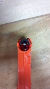
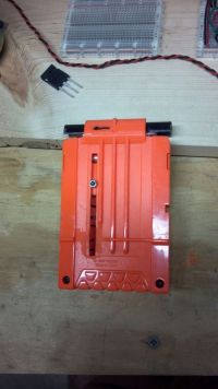
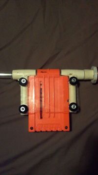
While I am still waiting for my order of igbt's and caps to come in, I got to work building the clip and locking mechanisms. It is made from a heavily modified Nerf clip and some 1/2" plastic pipe tees. The clip snaps into place with almost no play what so ever. This system will eventually be optimized and redesigned for the portable V3CC project to come, even though this initial attempt works well. As soon as my igbt's arrive I can test the injector and clip as a complete system.
Re: V3 Coil Carbine
ben5017, Wed Dec 05 2012, 06:43PM
Clip pics didnt upload for some reason last post, so here they are
ben5017, Wed Dec 05 2012, 06:43PM
Clip pics didnt upload for some reason last post, so here they are


Re: V3 Coil Carbine
Saz43, Sat Dec 08 2012, 03:16AM
Does it though? Every LiPo I've ever seen specifies a separate charge and drain rate. For example, my LiPos specify a 50C discharge rate, 100C burst rate, and a 1C charge rate, which comes with a warning not to charge over 1C or else damage can occur.
See #6 under charging instructions:
Ben, I admire your use of existing hardware. Keep up the good work.
Saz43, Sat Dec 08 2012, 03:16AM
Steve Conner wrote ...
How is this any worse for the battery than the equivalent discharge current? Surely for small increments of charge, the physics work the same both ways.
How is this any worse for the battery than the equivalent discharge current? Surely for small increments of charge, the physics work the same both ways.
Does it though? Every LiPo I've ever seen specifies a separate charge and drain rate. For example, my LiPos specify a 50C discharge rate, 100C burst rate, and a 1C charge rate, which comes with a warning not to charge over 1C or else damage can occur.
See #6 under charging instructions:

Ben, I admire your use of existing hardware. Keep up the good work.
Re: V3 Coil Carbine
Hanzie, Sat Dec 08 2012, 04:06PM
Saz is right, LiPos don't like high charge rates AT ALL. Though some may have a 65C continuous discharge, a charge rate of anywhere over 5 should be very much avoided. They will go boomzies with fire. Lots of fire. ^^
Also, you should always use a special LiPo-charger when charging your batteries as they need to charge differently from nickel or lead based cells.
Re: V3 Coil Carbine
Ash Small, Sat Dec 08 2012, 04:22PM
.....And with a firing rate of 150 rounds per minute (5 rounds in 2 seconds) the LiPo's are unlikely to be happy with that amount of current being dumped back into them.
Worst case will be fire or explosion, best case will be very short battery life, I assume.
It may well be cheaper in the long run to use non-polarised caps, and an appropriate switching circuit for the batteries, etc. if you wish to re-claim the wasted energy.
EDIT: Assuming 10% efficiency, if you use zeners to 'dump' the wasted energy, you'll need 10 times as many LiPo's for the same number of shots as you'd need if you use non-polar caps, etc. to re-claim the wasted energy anyway.
Re: V3 Coil Carbine
Steve Conner, Sat Dec 08 2012, 04:42PM
I'm pretty sure some brushless ESCs for RC cars incorporate regen braking. If your theory was right, that wouldn't be possible without destroying the batteries.
Steve Conner, Sat Dec 08 2012, 04:42PM
I'm pretty sure some brushless ESCs for RC cars incorporate regen braking. If your theory was right, that wouldn't be possible without destroying the batteries.
Re: V3 Coil Carbine
Yandersen, Sat Dec 08 2012, 07:40PM
Hey Ben, yesterday night I've got enlighted by ingenious idea for your battery-driven coilgun! I've invented the circuit which will recuperate energy, shorten the discharge AND charge time for your coils, will consume less of the battery energy and will not charge it at all! See the schematic:
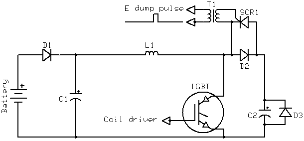
How it works.
As in your current design, coil is driven by IGBT transistor. Howhether, when it is switches off, current will deplete much faster due to discharge onto C2 cap. When coil is completely discharged, C2 will contain all recuperated energy. The less is C2 capacitance, the higher the voltage it will have. Then... Once projectile left the coil, you trigger SCR1 to return energy back to source - C2 will discharge through the coil in opposite direction, charging C1 to the voltage level which is higher than the battery voltage.
Wait a sec, the schematic has a bug - after current depletes, C1 will discharge back onto C2 through D2... Okay, give me some time, I think I know how to deal with this problem...
Yandersen, Sat Dec 08 2012, 07:40PM
Hey Ben, yesterday night I've got enlighted by ingenious idea for your battery-driven coilgun! I've invented the circuit which will recuperate energy, shorten the discharge AND charge time for your coils, will consume less of the battery energy and will not charge it at all! See the schematic:

How it works.
As in your current design, coil is driven by IGBT transistor. Howhether, when it is switches off, current will deplete much faster due to discharge onto C2 cap. When coil is completely discharged, C2 will contain all recuperated energy. The less is C2 capacitance, the higher the voltage it will have. Then... Once projectile left the coil, you trigger SCR1 to return energy back to source - C2 will discharge through the coil in opposite direction, charging C1 to the voltage level which is higher than the battery voltage.
Wait a sec, the schematic has a bug - after current depletes, C1 will discharge back onto C2 through D2... Okay, give me some time, I think I know how to deal with this problem...
Re: V3 Coil Carbine
Hanzie, Sat Dec 08 2012, 07:58PM
Steve, I've got some RC cars too. (I got way too many hobbies... xD) It's true they use the engine to brake, but as far as I know it doesn't charge the batteries with it. It's usually just very little reversed throttle. Hope that explains stuff a bit. ^^
Hanzie, Sat Dec 08 2012, 07:58PM
Steve, I've got some RC cars too. (I got way too many hobbies... xD) It's true they use the engine to brake, but as far as I know it doesn't charge the batteries with it. It's usually just very little reversed throttle. Hope that explains stuff a bit. ^^
Re: V3 Coil Carbine
Yandersen, Sat Dec 08 2012, 08:04PM
Aha! Here is the fixed schematic:
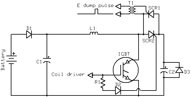
So, initial state:
C1 is charged to the [battery voltage-0.6V];
C2 has no charge;
IGBT' gate is at the ground level, as well as SCR2 gate and cathode.
When the projectile approaches the coil, you trigger your IGBT by charging it's gate to around dozen of volts, right? Then current starts to rise in the coil. When projectile is inside the coil, you are switching off the IGBT by lowering it's gate to the ground. During that process voltage across IGBT rises, making SCR2 able to handle the current flow and redirect it to the C2. When current depletes, all unused energy is stored in the C2, and SCR2 closes, capturing the energy inside that cap.
When projectile is outside the coil, you trigger SCR1 to return energy back into C1, so next shot coil will start charging from higher voltage, thus reusing some of the energy from last shot. When current depletes, voltage across C1 is higher than the battery voltage, and C2 is 0.6V below the ground level. SCR2 will not allow the current to flow back into C2, because it's gate at this moment is at the ground too. So we returned to the initial state with only one difference - next shot coil will be charged faster and use little less of battery.
Yandersen, Sat Dec 08 2012, 08:04PM
Aha! Here is the fixed schematic:

So, initial state:
C1 is charged to the [battery voltage-0.6V];
C2 has no charge;
IGBT' gate is at the ground level, as well as SCR2 gate and cathode.
When the projectile approaches the coil, you trigger your IGBT by charging it's gate to around dozen of volts, right? Then current starts to rise in the coil. When projectile is inside the coil, you are switching off the IGBT by lowering it's gate to the ground. During that process voltage across IGBT rises, making SCR2 able to handle the current flow and redirect it to the C2. When current depletes, all unused energy is stored in the C2, and SCR2 closes, capturing the energy inside that cap.
When projectile is outside the coil, you trigger SCR1 to return energy back into C1, so next shot coil will start charging from higher voltage, thus reusing some of the energy from last shot. When current depletes, voltage across C1 is higher than the battery voltage, and C2 is 0.6V below the ground level. SCR2 will not allow the current to flow back into C2, because it's gate at this moment is at the ground too. So we returned to the initial state with only one difference - next shot coil will be charged faster and use little less of battery.
Re: V3 Coil Carbine
Ash Small, Sat Dec 08 2012, 08:08PM
Well, there are several factors to consider here, firstly, in the case of regen. braking for RC cars, maybe the batteries are configured so that they only re-charge at the designed rate?...Although, as far as I'm aware, all the Lithium based batteries require the charge rate to be reduced to a few % of the initial charging rate as charging progresses (from what I read when I was designing a simple charger that runs off a 12V car battery for a Nintendo DSi, although they are lithium ion batteries in the DSi.)
I read quite a few stories about peoples cars going up in flames while they were re-charging LiPo's 'in the field', and the insurance companies not paying up because the chargers were faulty.
As others have pointed out, all the 'authorative sources' say that the 'proper charging procedures' must be adhered to for safety and reasonable battery life.
I assume a 'momentary burst' won't overheat them sufficiently to cause them to burst into flames, but it will still degrade them, I'd assume, and repeated bursts will presumably overheat them sufficiently to eventually cause a fire.
Maybe someone should run some tests to see what effect this has on them?
(I'm still of the opinion that, if they are near fully charged, as they would presumably be at the beginning of a day's 'shooting', they are likely to suffer some degradation.)
EDIT: I've just read the three previous posts by Hanzie and Yanderson. I think Yanderson is probably on the right track, placing a diode in series with the battery, etc. As far as Hanzie's point is concerned, I'm still trying to get my head round exactly how recupreated energy is used to slow the car down. Most of the KERS systems in formula 1 use some form of lithium battery as far as I'm aware (Williams and, I think, one other team use flywheels to store the recuperated energy) Red Bull consistently has problems with their batteries overheating, and several times in the past couple of seasons have had to disable the KERS system until the batteries cool down again. Maybe all you need to do is monitor battery temperature?
Ash Small, Sat Dec 08 2012, 08:08PM
Steve Conner wrote ...
I'm pretty sure some brushless ESCs for RC cars incorporate regen braking. If your theory was right, that wouldn't be possible without destroying the batteries.
I'm pretty sure some brushless ESCs for RC cars incorporate regen braking. If your theory was right, that wouldn't be possible without destroying the batteries.
Well, there are several factors to consider here, firstly, in the case of regen. braking for RC cars, maybe the batteries are configured so that they only re-charge at the designed rate?...Although, as far as I'm aware, all the Lithium based batteries require the charge rate to be reduced to a few % of the initial charging rate as charging progresses (from what I read when I was designing a simple charger that runs off a 12V car battery for a Nintendo DSi, although they are lithium ion batteries in the DSi.)
I read quite a few stories about peoples cars going up in flames while they were re-charging LiPo's 'in the field', and the insurance companies not paying up because the chargers were faulty.
As others have pointed out, all the 'authorative sources' say that the 'proper charging procedures' must be adhered to for safety and reasonable battery life.
I assume a 'momentary burst' won't overheat them sufficiently to cause them to burst into flames, but it will still degrade them, I'd assume, and repeated bursts will presumably overheat them sufficiently to eventually cause a fire.
Maybe someone should run some tests to see what effect this has on them?
(I'm still of the opinion that, if they are near fully charged, as they would presumably be at the beginning of a day's 'shooting', they are likely to suffer some degradation.)
EDIT: I've just read the three previous posts by Hanzie and Yanderson. I think Yanderson is probably on the right track, placing a diode in series with the battery, etc. As far as Hanzie's point is concerned, I'm still trying to get my head round exactly how recupreated energy is used to slow the car down. Most of the KERS systems in formula 1 use some form of lithium battery as far as I'm aware (Williams and, I think, one other team use flywheels to store the recuperated energy) Red Bull consistently has problems with their batteries overheating, and several times in the past couple of seasons have had to disable the KERS system until the batteries cool down again. Maybe all you need to do is monitor battery temperature?
Re: V3 Coil Carbine
Yandersen, Sat Dec 08 2012, 09:11PM
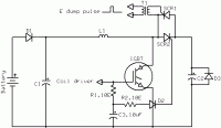
Sorry for the multiposting, I've just realized that IGBT will actually start to close some time after it's gate will drop down to 0 volts. If so, then this schematic will ensure that SCR2 opens after IGBT is closed:
Yandersen, Sat Dec 08 2012, 09:11PM
Sorry for the multiposting, I've just realized that IGBT will actually start to close some time after it's gate will drop down to 0 volts. If so, then this schematic will ensure that SCR2 opens after IGBT is closed:

Re: V3 Coil Carbine
ben5017, Mon Dec 10 2012, 01:42PM
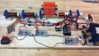
Got some work done on the X3CC this weekend. Both accelerator stages are up and running. As of now, I have no way of compiling performance data. How do you guys estimate velocity? Am I better off buying a cheap chronograph?
Anecdotal results: I was pleasantly surprised with the power from one stage + injector. The results from adding the second stage showed a noticeable increase in power, although I was expecting a bigger jump in performance after how well the first stage worked. This leads me to believe that it is nowhere near tuned at the moment.
Since I finally have a multi stages coil gun, I can now start experimenting and work out ways to optimize the design.

Re: V3 Coil Carbine
Hanzie, Mon Dec 10 2012, 03:52PM
Ash, those RC cars slow down by giving very little reversed throttle like they would when they drive backwards. As the car still drives forward, this works as a brake. I don't know how else to explain it, but as far as I'm aware there's no energy going back to the batteries. This wouldn't really be a whole lot anyways, so it's not really worth the trouble of putting such a system inside. Real-size cars may use the technique though.
As for the coilgun; Looking awesome so far Ben. ^^
Re: V3 Coil Carbine
Yandersen, Mon Dec 10 2012, 10:26PM
I check speed of mine by the oscilloscope and a piece of pipe with two optical gates distanced by 10cm from each other.
Ben, try a shorter projectile - it will give your coils a little more time to dessipate energy before suckbacking. Saz at least puts a bunch of serialized diodes to deplete current faster. BTW, I've tried a comparably little 1N5408 diode as dempher diode for the coil which had 100A running through - it sustained the surge pulse without even mentionable heating. Consider using small diodes - for a single surge you don't need iron monsters.
Re: V3 Coil Carbine
ben5017, Tue Dec 11 2012, 09:54PM
yaz: I am trying to gain some aerodynamic stability with the longer thinner projectiles, and hopefully improve the effective range of the carbine. The scar 1000's projectiles were shorter and fatter, and were unacceptably unstable, some would shoot stable and straight, others would buzz end over end. for the x3cc I made sure I found a barrel that fits absolutely perfect. I need the long heavy slugs to hit tip first in order to have sufficient penetrative power, hopefully these two changes in addition to the increased velocity will do the trick.
-As for my diodes. I just put those on there to test everything is working as expected. Now I will begin upgrading the various systems. Finding the optimal diodes, and flux augmentation are the first things on my list.
-Should I be looking for diodes primarily by there amperage and speed ratings?
-You had mentioned adding 5W zeners in series with my diodes? Can you explain how those would help and where the energy will get dissipated? What voltage zeners should I be looking for? 25V?(same as my battery)
-So IGBT half bridge, Nonpolar caps in parallel , and zeners in series with my diodes are 3 different ways to limit suck back?
Saz: did you ever measure the velocity of your stages with out external iron? Where did you get your powered iron?
Re: V3 Coil Carbine
Yandersen, Wed Dec 12 2012, 04:24AM
Ben, what is the voltage rating of your IGBT? Let's say it is 600V. Then put 3 zeners of 180V rating IN SERIES to get a little below 600V (540V you will get). The leftovers of your current will dissipate on those zeners almost instantly. You may parallelize few such strings of zeners to be sure it is not overwhelmed. The idea is to higher the voltage drop. When IGBT is switched off, current is circulating through the coil and zeners expiriencing R*I*I dissipation power running through the coil and V*I power dessipation over zeners (V is a voltage drop over the single zeners' string).
Just do this and forget about any suckback. But make sure nothing touches the coil during the voltage pulse shot... :)
Re: V3 Coil Carbine
ben5017, Wed Dec 12 2012, 03:09PM
Yan: Good guess, they are 600v, just ordered (24) 5w 180v zeners. Should I still be putting more dempher diodes in series also? Or with the addition zeners is this now not necessary? Will my IGBT experience any significant different conditions, like a spike in amperage or voltage that I should be concerned about?
Can you explain what will happen if something touches the coil, I assumed the enamel wire had enough dielectric strength that 600v would not be a problem.
Those 5W zeners can dissipate all the current in the coil? Over one hundred amps? Should I expect them to experience significant heating?
Re: V3 Coil Carbine
Yandersen, Wed Dec 12 2012, 09:28PM
No, just one dempher diode. It will dissipate almost nothing. Your IGBT will be scared by voltage spike, but I doubt it will be over 600V, so their pants will stay clean. Good question about the wire. Hardly it will blow inbetween the layers, but keep ends wrapped with additional insulation and away from each other. 540V is pretty dangerous, but you want to dessipate energy the fastest way possible, right?
Zeners will dissipate almost all energy stored in a coil (it is E=L*I*I/2, so you can estimate it if you know your coil inductance and current). The rest will be dissipated on coil resistance. Current will linearly decrease, and voltage will stay constant while the last electrone will die. When current stops, voltage will drop instantly from 540V to 0V. It will not be long. In fact, there are no any faster way to dissipate energy rather than let the coil shot a HV spike.
Re: V3 Coil Carbine
ben5017, Thu Dec 13 2012, 04:30PM
If my wire can blow between layers at 540V, how do some of you guys play with a couple thousand volts? Do you get wire with a special HV insulation?
ben5017, Thu Dec 13 2012, 04:30PM
If my wire can blow between layers at 540V, how do some of you guys play with a couple thousand volts? Do you get wire with a special HV insulation?
Re: V3 Coil Carbine
Yandersen, Thu Dec 13 2012, 09:44PM
"...about the wire. Hardly it will blow inbetween the layers, but keep ends wrapped with additional insulation and away from each other."
I play with 780V. No accidents since I started to insulate iron washers holding the coil from both ends. Used just 1 layer of paper glued to the washer by epoxy.
Re: V3 Coil Carbine
ben5017, Tue Dec 18 2012, 05:46PM
Yan, I miss understood your previous post.
Update: I got the zeners set up on both the accelerator stages. It seemed to give a slight increase in velocity, since the sensor is now right up against the coils while minimizing suckback. I have no way (as of yet) to measure the velocity so I have no hard data to provide. However I will put together some data and share it showing various different configurations and average results for each once I do.
Re: V3 Coil Carbine
Yandersen, Tue Dec 18 2012, 10:13PM
I just highlighted th word "ends" which means you have to pay special attention only on insulation of wire ends sticking out of the coil bobbin, as it is 540V inbetween them.
You can roughly estimate the difference in kinetic energy by shooting into a modelling clay by the deepness of penetration.
If you are ready to be more precise, you can mount two optic gates on a piece of pipe, sensors distanced by, say, 10cm from each other, and check the time it takes for projectile to pass from one sensor to the next via an oscilloscope connecting probes to the optic sensors.
Re: V3 Coil Carbine
MrFlatox, Sun Jan 20 2013, 09:37AM
Hi !
I am also planning to build a LiPO powered coilgun, so I've naturally read this thread. You are talking about putting a zener diode in series of the damper diode to hasten the current drop in the coil, and thus preventing any suckback effects. As I plan to use mosfet to switch main current, I must choose a zener diode with voltage rating just a little below my maximum drain to source voltage ok ? I tried to simulate this , and I got that :

Graph shows the voltage that the mosfet will see. For this simulation, I chose a 51V zener diode. My question is : Why do I get 130V peak voltage with a 51V zener diode ? Is my schematic wrong ?
Thanks in advance
MrFlatox, Sun Jan 20 2013, 09:37AM
Hi !
I am also planning to build a LiPO powered coilgun, so I've naturally read this thread. You are talking about putting a zener diode in series of the damper diode to hasten the current drop in the coil, and thus preventing any suckback effects. As I plan to use mosfet to switch main current, I must choose a zener diode with voltage rating just a little below my maximum drain to source voltage ok ? I tried to simulate this , and I got that :

Graph shows the voltage that the mosfet will see. For this simulation, I chose a 51V zener diode. My question is : Why do I get 130V peak voltage with a 51V zener diode ? Is my schematic wrong ?
Thanks in advance
Re: V3 Coil Carbine
Ash Small, Sun Jan 20 2013, 11:25AM
Try putting a capacitor accross the zener. If the zener is taking a few uS to 'kick in', this should stop the voltage rising until the zener starts 'doing it's job'.
I can't be certain I'm right, but it's worth adding a cap to the simulation to see. Maybe ~500uF, but I'm guessing here. Try a few different values.
EDIT: It may be better to try a capacitor accross the MOSFET instead.
Ash Small, Sun Jan 20 2013, 11:25AM
MrFlatox wrote ...
Graph shows the voltage that the mosfet will see. For this simulation, I chose a 51V zener diode. My question is : Why do I get 130V peak voltage with a 51V zener diode ? Is my schematic wrong ?
Thanks in advance
Graph shows the voltage that the mosfet will see. For this simulation, I chose a 51V zener diode. My question is : Why do I get 130V peak voltage with a 51V zener diode ? Is my schematic wrong ?
Thanks in advance
Try putting a capacitor accross the zener. If the zener is taking a few uS to 'kick in', this should stop the voltage rising until the zener starts 'doing it's job'.
I can't be certain I'm right, but it's worth adding a cap to the simulation to see. Maybe ~500uF, but I'm guessing here. Try a few different values.
EDIT: It may be better to try a capacitor accross the MOSFET instead.
Re: V3 Coil Carbine
Yandersen, Sun Jan 20 2013, 11:42AM
Please, don't listen to the suggestion above.
Voltage is higher because of the coil's resistance and zener parasitic resistance - both add voltage drop due to the current running through. Coil resistance should be considered as unavoidable, but zener can be found with better parameters. Voltage drop for different currents are usually given in a datasheet table for TVS diodes.
Simulation seems to look right.
Re: V3 Coil Carbine
MrFlatox, Sun Jan 20 2013, 02:09PM
So how could I protect the mosfets, and have a quick de-energization of the coil at the same time ?
For example, let's say I am using a 75V mosfet, (or multiple stacked in parallel) and my battery provides 33V, what should I do to prevent the mosfets from blowing up, and have the fastest current decay in the coil.
Another question : in a battery powered coilgun, the maximum current that could circulate is dictated by the discharge rate of the battery, so the load (the coil) should be designed so that its internal resistance matches the max current the battery could supply ? Or is there another way, for a given coil and battery, to limit the current the coil receives and thus the current the battery is giving ?
Thanks
Re: V3 Coil Carbine
Ash Small, Sun Jan 20 2013, 02:27PM
Surely a capacitor accross the MOSFET will absorb the spike and protect the mosfet?
It's a fairly standard snubber device.
Ash Small, Sun Jan 20 2013, 02:27PM
Yandersen wrote ...
Please, don't listen to the suggestion above.
Please, don't listen to the suggestion above.
Surely a capacitor accross the MOSFET will absorb the spike and protect the mosfet?
It's a fairly standard snubber device.
Re: V3 Coil Carbine
Yandersen, Sun Jan 20 2013, 05:11PM
Hard to predict the exact capacitance value.
Flatox, just put more powerfull zener with a bit smaller clamping voltage.
For 33V battery and 75V MOSFET you have 42V of maximum drop at a coil (so ideally current may decay just a little bit faster than it's rizes). If you limit the current by coil' resistance, than you will have the same 33V drop on coil and zener may be up to 42-33=9V. Zener will not do much difference. The less V drop is on resistance opposite to the zener, the more linear and fast current decay will be. Limiting current by resistance is bad anyway.
Re: V3 Coil Carbine
MrFlatox, Sun Jan 20 2013, 05:37PM
I have just tried this, and it makes an ugly oscilating LC circuit. I do not think that it would make things better at the end.
If my simulation is correct, then using zener diodes will never make the mosfet live because voltage spike is never under 160V, no matter the Vzener voltage I choose.
MrFlatox, Sun Jan 20 2013, 05:37PM
Ash Small wrote ...
Surely a capacitor accross the MOSFET will absorb the spike and protect the mosfet?
It's a fairly standard snubber device.
Surely a capacitor accross the MOSFET will absorb the spike and protect the mosfet?
It's a fairly standard snubber device.
I have just tried this, and it makes an ugly oscilating LC circuit. I do not think that it would make things better at the end.
If my simulation is correct, then using zener diodes will never make the mosfet live because voltage spike is never under 160V, no matter the Vzener voltage I choose.
Re: V3 Coil Carbine
Ash Small, Sun Jan 20 2013, 06:44PM
Did it keep the voltage 'within limits'?
You could try putting a fast diode in series with the capacitor, to stop the oscillations. You'd could also put a high value (mega Ohms) resistor in parallel with the capacitor, to drain it after each shot. (there are other ways to drain it).
(It's just another solution that you could try simulating, and compare it with other suggestions. Did you try other capacitor values?.)
EDIT: This capacitor, diode and resistor circuit I've described is a standard snubber circuit used to protect silicon and prevent oscillations. There are other variations used, but this is one of the more common ones. It could also protect the MOSFET in the event of TVS failure.
Ash Small, Sun Jan 20 2013, 06:44PM
MrFlatox wrote ...
I have just tried this, and it makes an ugly oscilating LC circuit. I do not think that it would make things better at the end.
If my simulation is correct, then using zener diodes will never make the mosfet live because voltage spike is never under 160V, no matter the Vzener voltage I choose.
Ash Small wrote ...
Surely a capacitor accross the MOSFET will absorb the spike and protect the mosfet?
It's a fairly standard snubber device.
Surely a capacitor accross the MOSFET will absorb the spike and protect the mosfet?
It's a fairly standard snubber device.
I have just tried this, and it makes an ugly oscilating LC circuit. I do not think that it would make things better at the end.
If my simulation is correct, then using zener diodes will never make the mosfet live because voltage spike is never under 160V, no matter the Vzener voltage I choose.
Did it keep the voltage 'within limits'?
You could try putting a fast diode in series with the capacitor, to stop the oscillations. You'd could also put a high value (mega Ohms) resistor in parallel with the capacitor, to drain it after each shot. (there are other ways to drain it).
(It's just another solution that you could try simulating, and compare it with other suggestions. Did you try other capacitor values?.)
EDIT: This capacitor, diode and resistor circuit I've described is a standard snubber circuit used to protect silicon and prevent oscillations. There are other variations used, but this is one of the more common ones. It could also protect the MOSFET in the event of TVS failure.
Re: V3 Coil Carbine
MrFlatox, Sun Jan 20 2013, 08:42PM
It lowered the voltage spike when using high value capacitor, but the oscilations are just too big. I will try your suggestions about the diode and resistor.
As you are talking about TVS, does a TVS diode with a voltage rating of 60V would do the same thing as my diode plus zener diode in series ? It could be intresting because they can pass a lot of current, and are cheap.
Re: V3 Coil Carbine
Ash Small, Sun Jan 20 2013, 09:46PM
TVS's (transient voltage suppressors) and zeners do pretty much the same thing,as far as I'm aware, but I can't quote any specs or anything for either. I'm still learning this stuff too.
I've researched snubbers quite a bit though, for protecting transistors of all types from voltage spikes. Adding a fast diode kills the oscillations. A high value resistor will discharge the cap each time you fire, and not really affect the rest of the circuit,. You'd need to research'experiment/simulate the exact values/specs yourself, though. It should also protect the MOSFET in case of zener/TVS failure, etc.
Ash Small, Sun Jan 20 2013, 09:46PM
MrFlatox wrote ...
It lowered the voltage spike when using high value capacitor, but the oscilations are just too big. I will try your suggestions about the diode and resistor.
As you are talking about TVS, does a TVS diode with a voltage rating of 60V would do the same thing as my diode plus zener diode in series ? It could be intresting because they can pass a lot of current, and are cheap.
TVS's (transient voltage suppressors) and zeners do pretty much the same thing,as far as I'm aware, but I can't quote any specs or anything for either. I'm still learning this stuff too.
I've researched snubbers quite a bit though, for protecting transistors of all types from voltage spikes. Adding a fast diode kills the oscillations. A high value resistor will discharge the cap each time you fire, and not really affect the rest of the circuit,. You'd need to research'experiment/simulate the exact values/specs yourself, though. It should also protect the MOSFET in case of zener/TVS failure, etc.
Re: V3 Coil Carbine
Yandersen, Mon Jan 21 2013, 06:25AM
Guys, I'm sick hearing about your ridiculous computer simulations for circuits with 3 parts! Do any of you ever hold a soldering iron in a hand and an oscilloscope nearby? Your simulations are either wrongly done or simply away from reality. What do you think you are "learning" without practicing? For the whole month 4HV are dancing around TVS diodes antiparallel to the coils and seems like noone understands a thing.
Ah, I'm just in a bad mood. What are we talking around here?..
Re: V3 Coil Carbine
Ash Small, Mon Jan 21 2013, 01:15PM
Yan, I don't do simulations either, I once downloaded a free version of SPICE, but couldn't be bothered to spend hours and hours learning how to use it. I just use a 'scope and a breadboard and see what happens in reality. I was working on snubbers a few months ago, but had to stop because I didn't have any fast diodes. I have some now, but my breadboard now has another project on it, so I've not got around to continuing with my snubber 'experiments'. I also use the minimum amount of maths that I can get away with. I also try to use the best quality components which are generally over rated for what I need, although sometimes I just use what I can get or already have.
I do take an interest in other peoples simulations though.
All that is required here is a capacitor with a high enough value to reduce the voltage spike to 'acceptable levels', and a diode that is fast enough to 'kill' any oscillations and handle the current, plus a resistor that only has to discharge the capacitor before the next shot.
Just using 'trial and error' will kill quite a few MOSFET's in the process, so a simulation should reduce the number of MOSFET's that have to die before the correct values are found.
All I'm doing here is suggesting an alternative to what you've suggested, and which should also protect the MOSFET in the case of TVS/diode failure. Your solution is simpler because it uses less components, but mine is arguably more reliable.
I'm simply pointing out an alternative method to achieve the same thing, ie, to reduce the voltage spike accross the MOSFET.
It could be argued that the best solution would be to implement both, if space and availability of components allow it, certainly at the breadboarding stage.
Re: V3 Coil Carbine
Yandersen, Tue Jan 22 2013, 03:57AM
Okay...
Yandersen, Tue Jan 22 2013, 03:57AM
Okay...
Re: V3 Coil Carbine
ben5017, Tue Mar 05 2013, 04:05PM
Update:
-Added 3rd accelerator stage
-Modified coil geometry (removed 1/2 layer from each subsequent stage to compensate for decreased "on" time due to higher V initial (trying to keep amps approx same each stage to maximize power through the igbt))
-Removed diode/zener protection (replace with (3) 5kw tvs diodes in series (540V totalbreakdown voltage))
-Minimized circuit size and moved all to one board
-Remade sensors into interchangeable units
-Added Fuse box (separate fuses for each stage + injector + cap bank)
Additional Changes to be made:
-Add cap bank to increase discharge rate (from 45C (lipo) to 85C (Caps))
-Add selector switch to change between monostable and astable 556 chip to drive injector
-6s lipo instead of 5s
Test shot results.
(3 stage no injector) approx 75mm penetration into solid Styrofoam block.
(3 stage no injector) through beer can, 35mm penetration Styrofoam.
Current Bugs:
First stage works perfectly when just testing the sensor, however when I actually shoot it, it stays on, blows the fuse and the 421 inverting gate driver??? Having trouble figuring out the issue...
Also I cannot get my 556 edge triggered monostable to work correctly (I have made this circuit numerous times with no issues....)
I am starting to think my breadboard is F***** up, it has been doing some weird stuff.....


Re: V3 Coil Carbine
Yandersen, Tue Mar 05 2013, 09:00PM
I had both of those bugs. Latchup of optical gate may have many reasons. The one I have encountered was sensitivity of photodetector to the EMI from coil - when coil shuts off, sensor gives driver the white noise which ends up in continuous on-off oscillations blowing the driver and possibly switch.
The issue with 556 timer is a strange coupling between output and trigger. When I connect OUT directly to mosfet gate and mosfet is switching off, the parasitic capacitance between drain and gate forcing the gate and timer's OUT in turn. For some reason that spike acts like a triggering signal for timer. Had no such issue with NA/NE/SE/TLC-555 timers though... Add 100 Ohm resistor for the output of 556 to prevent current overloading - worked for me.
Re: V3 Coil Carbine
Maxwell, Wed Mar 06 2013, 12:38AM
@Ben5017
Since you have optical gate triggering - why not buy a cheap arduino and count the time between gate triggers - will provide you with a pretty accurate velocity?
Maxwell, Wed Mar 06 2013, 12:38AM
@Ben5017
Since you have optical gate triggering - why not buy a cheap arduino and count the time between gate triggers - will provide you with a pretty accurate velocity?
Re: V3 Coil Carbine
ben5017, Thu Mar 07 2013, 02:57PM
Yan:
About my firing topology. I actually have the sensor triggering a 555 which in turn, puts the output low then to the inverting igbt gate driver.
As for my bug. Turned out I had a bad 555 timer, (a good portion of the 555's I just got of mouser were defective so I kept replacing a bad one with a bad one.... as well as a shaky at best breadboard).
That being said could the sensor still cause the same issues on the 555 as on the igbt driver?
What is a good way to protect the sensors?
-Would making the sensor housing out of powdered ferrite help isolate the phototransistor from the emi?
MAXWELL:
I just bought a few microprocessors (mega 8 I think couple others) to mess around with, but I have never used one and don’t know where to start... Maybe taking the time to learn and replacing all my firing circuits with a microchip might be the way to go, I am a bit intimidated to try as I have no idea where to begin.
NEW ISSUES:
1) Injector sometimes (maybe 1 out of 10) fires when I release the trigger? ( Topology, adjustable pulse length 555 edge trigger mono stable, connected to 422 driver)
Any thoughts?
2) I hooked up my injector and fired a few shots, ever since then the Resistance on my igbts when open is 14K ohms, (same on all igbts (3 stages +injector))?? As you can imagine this drastically reduced velocity. I have tried everything to figure out what’s going on (changed 555, drivers, IGBT's) I still cannot figure it out.
Re: V3 Coil Carbine
Maxwell, Thu Mar 07 2013, 06:26PM
If you have $25 and a USB cable laying around, buy any arduino you can easily get your hands on. I'll write the timing code for you. Real simple coding. FYI - the DUO utilizes the microUSB connector - which breaks easily.
Atmega8's will require an external programmer - something I don't venture off into.
Maxwell, Thu Mar 07 2013, 06:26PM
ben5017 wrote ...
MAXWELL:
I just bought a few microprocessors (mega 8 I think couple others) to mess around with, but I have never used one and don’t know where to start... Maybe taking the time to learn and replacing all my firing circuits with a microchip might be the way to go, I am a bit intimidated to try as I have no idea where to begin.
If you have $25 and a USB cable laying around, buy any arduino you can easily get your hands on. I'll write the timing code for you. Real simple coding. FYI - the DUO utilizes the microUSB connector - which breaks easily.
Atmega8's will require an external programmer - something I don't venture off into.
Re: V3 Coil Carbine
ben5017, Thu Mar 07 2013, 06:35PM
That would be awesome Maxwell. I will buy one today after I get out of work. Will any arduno work? Which one would you recommend? It’s long over due for me to start playing with the microchips. You think I could "reverse engineer" the code to learn how to program them?
Do you think changing to digital would have any significant effect on performance?
Re: V3 Coil Carbine
ben5017, Thu Mar 07 2013, 08:18PM
just picked up an arduino mega 2560, now just waiting for that code maxwell haha
ben5017, Thu Mar 07 2013, 08:18PM
just picked up an arduino mega 2560, now just waiting for that code maxwell haha
Re: V3 Coil Carbine
Yandersen, Thu Mar 07 2013, 09:25PM
I gave up with optical sensing already as even full metal shielding doesn't solve the problem completely. So the sensor must be as far from coil as possible. Either use laser diodes to stretch the beam, or optical cable to drive it away from coil to somewhere where EMI is low enough to not interfere with sensor. I would recommend optical cables as you can stretch all optowires in one place where all sensors and microcontroller are located - no low-current electronics works near the high pulsed magnetic fields.
Issue 1 is not surprising - common problem caused by mechanical switch. Hardly solvable - switch always glitches a little when contacts are connected or disconnected giving some false signals due to microvibrations. You can involve microcontroller to filter those false pulses: after triggering occurs make it insensitive for any other state changes for some period of time. For example...
My solution is two push buttons and a 555 timer - one button switches power supply on, another - switches it off and initiates firing sequence.
If you think smg may be wrong with yours IGBT, measure it outside the circuit, having gate and emitter connected. 14K may be given by other elements or some small floating positive voltage on gate.
Re: V3 Coil Carbine
Maxwell, Fri Mar 08 2013, 02:40AM
Quick Reply: Modifying my code for you to be able to understand. I'll have it posted (edited here) before midnight.
Code is posted below.
I haven't used the Mega in a year or two - but it should like this code.
Serial communications are established thru USB (make sure the baud rate on the arduino side is 9600)
variable delta x is the distance between photogates in mm.
Digital pin 3 is declared as an input. It will accept 0-5v (use a high impedance voltage divider just for safety for your trigger). When a HIGH signal is read, a de-bounce code pauses for 225ms (what I found to be fool-proof for my simple mechanical switches. IF you are doing a direct contact you may drop this down to 1 or 2ms).
Digital pins 10,11 are the photogate pins. They have a timeout in the speed_trap function that will declare an error if nothing passes between within 500ms. When the signal goes high to a pin from the photogate, the timers are triggered.
Variable 'engage' is the modular part - you can set the Arduino to jump to different functions by the number assigned to engage. I assumed engage 0 to mean waiting for trigger, engage 1 is trigger actuated.
Re: V3 Coil Carbine
ben5017, Fri Mar 08 2013, 03:14AM
You are the man. I love this place...
ben5017, Fri Mar 08 2013, 03:14AM
You are the man. I love this place...
Re: V3 Coil Carbine
Maxwell, Fri Mar 08 2013, 03:58AM
//Okay, so I down-compiled my code into this small format.
//Ask if you have any questions.
//It's not running 100% efficient but it is modular.
volatile byte engage; //Declare 'interrupts' as volatile
byte tabA;
byte darkA;
byte darkB;
unsigned int deltax; //Timer spacing in mm
unsigned int thrutime;
unsigned long dlaytimeA;
unsigned long dlaytimeB;
void setup()
{
Serial.begin(9600); //Reserve Digital Pins 0 and 1 for Serial
//on Duemillanove but not on Leonardo.
darkA=0; //Set initial Speedtrap ADC values
darkB=0;
engage=0; //Trigger status flag
pinMode(3,INPUT); //Pseudo-Interrupt pin (trigger)
pinMode(10,INPUT); //PhotoGate Entry
pinMode(11,INPUT); //PhotoGate Exit
deltax = 80; //Speedtrap light spacing in mm
}
void loop()
{
if(digitalRead(3)==HIGH && tabA==0)
{dlaytimeB=millis()+225; tabA=1;} //digital de-bounce script (225ms)
if(millis()>(dlaytimeB))
{tabA=0;}
if(tabA==1 && millis()>dlaytimeB && digitalRead(3)==HIGH)
{Serial.println("Trigger Action Detected."); engage=1; tabA=0;}
if(engage==1)
{
speed_trap(10,11); //digitalPin# entry, digitalPin# exit
}
if(engage==2)
{ if(thrutime==0)
{ Serial.println("Timing error. No timer activity detected."); }
else
{ calculations(); }
engage=0; //reset fire sequence
}
}
void speed_trap(int vinpinA, int vinpinB)
{ unsigned long enter; unsigned long exit;
unsigned long error; int errorcount = 0;
unsigned long errortime;
errortime=millis()+500; //500ms timeout for non-speedtrap triggering.
while(darkA==0 && errorcount!=1)
{ darkA=digitalRead(vinpinA); error=millis();
if(error>errortime){errorcount=1;}
}
enter=micros();
while(darkB==0 && errorcount!=1)
{ darkB=digitalRead(vinpinB); error=millis();
if(error>errortime){errorcount=1;}
}
exit=micros();
if(errorcount==0)
{ thrutime=(exit-enter); } //time in microseconds (1000us in 1ms)
else
{ thrutime=0; }
engage=2;
}
void calculations()
{
float velocity;
velocity = (deltax/1000.0) / (thrutime/1000000.0);
Serial.print("Thrutime (us): "); Serial.println(thrutime);
Serial.print("Velocity (m/s): ");Serial.println(velocity);
Serial.println("calculations function completed.");
}
Re: V3 Coil Carbine
ben5017, Fri Mar 08 2013, 02:56PM
Thanks alot. What do you think about me changing all my firing circuit into arduino? worth it?
ben5017, Fri Mar 08 2013, 02:56PM
Thanks alot. What do you think about me changing all my firing circuit into arduino? worth it?
Re: V3 Coil Carbine
Maxwell, Fri Mar 08 2013, 04:29PM
My full code controls the charging, triggering, speedgates and efficiency calculations.
I have a high-impedance voltage divider measuring charge voltage.
I use the Atmega's interal SRAM to take ~100 instantaneous voltage measurements during the discharge (make-shift oscilloscope) before my code jumps to measure velocity.
False triggering and spontaneous charging is somewhat an issue. In my next build, I will implement optocouplers to the HV and charging circuits. For now, i have some transistors that ground out all critical gates after the firing process completes.
The mega is very very capable. Lots of I/O and a large amount of memory.
Try not to fry pins - it makes programming a little more complicated. ;) I found out that they don't like direct exposure to 400v.
Re: V3 Coil Carbine
ben5017, Fri Mar 08 2013, 05:32PM
can you send me triggerin code pretty please
ben5017, Fri Mar 08 2013, 05:32PM
can you send me triggerin code pretty please
Re: V3 Coil Carbine
Maxwell, Fri Mar 08 2013, 06:42PM
Just the part to trigger an SCR?
Thats only like 3 new lines of code:
pinMode(4,OUTPUT); //SCR Gate Output (through TIP-120 transistor)
if(engage==1)
{
digitalWrite(4,HIGH) ; //pin 4 goes high to transistor
delay(1); //delay 1ms
digitalWrite(4,LOW);
speed_trap(10,11); //digitalPin# entry, digitalPin# exit
}
Re: V3 Coil Carbine
ben5017, Fri Mar 08 2013, 07:57PM
need to link up my optical sensors to the arduino then output to igbt
ben5017, Fri Mar 08 2013, 07:57PM
need to link up my optical sensors to the arduino then output to igbt
Re: V3 Coil Carbine
ben5017, Fri Mar 15 2013, 01:07AM
max, how about an adjustable one shot timer?
ben5017, Fri Mar 15 2013, 01:07AM
max, how about an adjustable one shot timer?
Re: V3 Coil Carbine
Maxwell, Fri Mar 15 2013, 01:19PM
@ben5017 - I just saw your post.
Explain specifically the order in which you would like things to happen and I can code it up for you no problem
Maxwell, Fri Mar 15 2013, 01:19PM
@ben5017 - I just saw your post.
Explain specifically the order in which you would like things to happen and I can code it up for you no problem
Re: V3 Coil Carbine
ben5017, Sun Mar 17 2013, 06:55AM
Max this is what I need
Phase 1:
1: pulling the trigger activates a 1shot trigger output with an adjustable pulse length.
2:when a switch is flipped, pulling and holding the trigger no longer oneshots but puts it into astable output with adjustable on/off times.
3:(x5) sensor setups that will be connected to the output of my optical gates (IR diode + opamp) which when a slug blocks the beam the arduino will send a signal to my igbt gate drivers.
the above is the minimum things I need right now to fire the x3cc.
Phase 2:
After that I will be working on the drum magazine which will hold 30+ slugs. I plan on connecting it to a continuous rotation servo or a dc/gear reducer motor, or maby a stepper, haven't decided yet. these will be controlled by the arduino which will read a signal from a hall effect sensor that will detect the presence of a slug. The arduino will rotate the motors as soon as it doesn't detect anything, until it does. the sensitivity will need to be adjustable as well to dial the feeding system in.
phase 3:
The frame will be the final step after it is firing/feeding acceptable and i get my cnc router fully operational.
Hope this helps.
Re: V3 Coil Carbine
ben5017, Tue Mar 19 2013, 03:16AM
update:
phase 1: #3 Done
got the firing code for one of my optical sensors working, along with an auto calibration of the sensor upon program start up to set expected max min values, along with a manual sensitivity adjustment 0-255. still have to add the rest of the stages. The sensor is super sensitive. cant wait to see If it makes it shoot any faster. (Would the arduino digital output be that much quicker than a 555?)
next up is the triggering code. I messed around with modifying a De-bouncing trigger code for a bit today. trying to act as a adjustable pulse "one shot", with out much luck. Haven't given much thought to the select fire yet either.(max where you at bro??)
Re: V3 Coil Carbine
Maxwell, Wed Mar 20 2013, 02:02AM
Hi ben5017,
Been quite busy with other things at the moment - apologies on the delayed code.
The arduino can output hellafast for what it is - roughly 1059times/millisecond without overhead.
You can use the delaymicroseconds command to turn on/off very quickly:
"
digitalWrite(outPin, HIGH); // sets the pin on
delayMicroseconds(50); // pauses for 50 microseconds
digitalWrite(outPin, LOW); // sets the pin off
"
Re: V3 Coil Carbine
Yandersen, Wed Mar 20 2013, 10:27AM
How about some noise-supression to prevent possible false-triggering? ALL inputs must become insensitive to ANY signals for a dozen microseconds every time after ANY of the coils got energized or switched off, as this process emits high level EMI.
Yandersen, Wed Mar 20 2013, 10:27AM
How about some noise-supression to prevent possible false-triggering? ALL inputs must become insensitive to ANY signals for a dozen microseconds every time after ANY of the coils got energized or switched off, as this process emits high level EMI.
Re: V3 Coil Carbine
ben5017, Wed Mar 20 2013, 05:12PM
yan:
1 step ahead of you. Have a few picked out. I dunno how to size them though. Take a look if you get a chance http
Max: gonna mess around with the injector driver code tonight. Ill keep you posted. Thanks for the tips. Any more commands you think might be usefull? links to a good refrence?
ben5017, Wed Mar 20 2013, 05:12PM
yan:
1 step ahead of you. Have a few picked out. I dunno how to size them though. Take a look if you get a chance http

Max: gonna mess around with the injector driver code tonight. Ill keep you posted. Thanks for the tips. Any more commands you think might be usefull? links to a good refrence?
Re: V3 Coil Carbine
Yandersen, Wed Mar 20 2013, 07:20PM
C'mon, Ben, that will not work. If you don't want to put protection code in software preferring the hardware way, then the only solution is to distance sensors away of coils by use of optocables (I believe we discussed that already). I would use both ways - hardware to remove false signals, software to control error conditions such as voltage downdrops, latch-up, triggering level adjustments (external light and IR sources like fire may interfere also), ensure consequence switching and so on. Later on you will find plenty of things to control and doing them all in hardware way may lead to a huge PC board.
Re: V3 Coil Carbine
Maxwell, Thu Mar 21 2013, 12:06PM
I've witnessed the sensitivity as well.
I see two options - completely isolate the two circuits with optocouplers and digital signals.
Or
Use a bunch of digital de-bounce code. This will slightly slow down the arduino, but should work.
If you ever get your hands on the new duo, it has a crazy fast clock on it - you could include high/low pass digital filters no problem.
Re: V3 Coil Carbine
Yandersen, Thu Mar 21 2013, 10:18PM
I have 0 exp with microcontrollers, but common sense dictates that each optosensor should be actually listened in a specified timeframe. EMI from one stage may affect wires of ALL optosensors acting like an antennas. As I once checked everything with oscilloscope, even if optosensor lays 5cm away from coil, still it can receive few dozens uA of current when coil get switched on and off (mention no galvanic connection between coil board and a sensor board - pure EMI through air). So if any coil is to be switched on or off, first thing to do is to cut out all inputs for a dozen of us, then continue with coil switching, and after a pause resume checking inputs. I have no idea how could it be done, as I have 0 exp with MC...
Re: V3 Coil Carbine
ben5017, Fri Mar 22 2013, 01:50AM
Max: if you get a chance take a look at my code. Only 1 stage is working. I probably messed up when adding the code for the extra stages.
/*
Calibration
calibrates the optical sensor input. The sensor takes a reading during the first 2.5 seconds of startup
to set the minimum and maximum of expected values of the sensor.
*/
///////////////////////////////////////////////// //////constants/////////////////////////////////// //////////////
// optical sensor constants:
// stage 1
const int sensorPin1 = A3; // pin that the sensor 1 is attached to
const int ledPin1 = 10; // pin that the LED1 is attached to
const int driverinput1 = 6; //injector driver 1 input
//stage 2
const int sensorPin2 = A5; // pin that the sensor 2 is attached to
const int ledPin2 = 8; // pin that the LED1 is attached to
const int driverinput2 = 4; //injector driver 2 input
//stage 3
const int sensorPin3 = A7; // pin that the sensor 3 is attached to
const int ledPin3 = 12; // pin that the LED1 is attached to
const int driverinput3 = 2; //injector driver 3 input
//////////////////////////////////////// //////////////variables/////////////////////////// /////////////////////////////////////////////////
// optical sensor variables:
// stage 1
int sensorValue1 = 0; // the sensor value
int sensorMin1 = 500; // minimum sensor value
int sensorMax1 = 1; // maximum sensor value
// stage 2
int sensorValue2 = 0; // the sensor value
int sensorMin2 = 500; // minimum sensor value
int sensorMax2 = 1; // maximum sensor value
// stage 3
int sensorValue3 = 0; // the sensor value
int sensorMin3 = 500; // minimum sensor value
int sensorMax3 = 1; // maximum sensor value
////////////////////////////////////////// /////////optical sensor code stage 1///////////////////////////////////////////////// ////////////////////
void setup() {
// turn on LED to signal the start of the calibration period:
pinMode(12, OUTPUT);
digitalWrite(12, HIGH);
// calibrate during the first five seconds
while (millis() < 2500) {
sensorValue1 = analogRead(sensorPin1);
// record the maximum sensor value
if (sensorValue1 > sensorMax1) {
sensorMax1 = sensorValue1;
}
// record the minimum sensor value
if (sensorValue1 < sensorMin1) {
sensorMin1 = sensorValue1;
}
}
// signal the end of the calibration period
digitalWrite(12, LOW);
}
void loop() {
// read the sensor:
sensorValue1 = analogRead(sensorPin1);
// apply the calibration to the sensor reading
sensorValue1 = map(sensorValue1, sensorMin1, sensorMax1, 0, 255);
// in case the sensor value is outside the range seen during calibration
sensorValue1 = constrain(sensorValue1, 0, 255);
// fade the LED using the calibrated value:
analogWrite(ledPin1, sensorValue1);
{
pinMode(6, OUTPUT);
if
(sensorValue1 < 250) // Change value to adjust sensitivity 1-255 increasing the value, increases the sensitivity
digitalWrite(6, HIGH);
else
digitalWrite(6, LOW);
///////////////////////////////////////////////// //optical sensor code stage 2///////////////////////////////////////////////// ////////////////////
// turn on LED to signal the start of the calibration period:
pinMode(10, OUTPUT);
digitalWrite(10, HIGH);
// calibrate during the first five seconds
while (millis() < 2500) {
sensorValue2 = analogRead(sensorPin2);
// record the maximum sensor value
if (sensorValue2 > sensorMax2) {
sensorMax2 = sensorValue2;
}
// record the minimum sensor value
if (sensorValue2 < sensorMin2) {
sensorMin2 = sensorValue2;
}
}
// signal the end of the calibration period
digitalWrite(10, LOW);
// read the sensor:
sensorValue2 = analogRead(sensorPin2);
// apply the calibration to the sensor reading
sensorValue2 = map(sensorValue2, sensorMin2, sensorMax2, 0, 255);
// in case the sensor value is outside the range seen during calibration
sensorValue2 = constrain(sensorValue2, 0, 255);
// fade the LED using the calibrated value:
analogWrite(ledPin2, sensorValue2);
{
pinMode(4, OUTPUT);
if
(sensorValue2 < 250) // Change value to adjust sensitivity 1-255 increasing the value, increases the sensitivity
digitalWrite(4, HIGH);
else
digitalWrite(4, LOW);
////////////////////////////////////////////////// /optical sensor code stage 3///////////////////////////////////////////////// //////////////////////////
// turn on LED to signal the start of the calibration period:
pinMode(8, OUTPUT);
digitalWrite(8, HIGH);
// calibrate during the first five seconds
while (millis() < 2500) {
sensorValue3 = analogRead(sensorPin3);
// record the maximum sensor value
if (sensorValue3 > sensorMax3) {
sensorMax3 = sensorValue3;
}
// record the minimum sensor value
if (sensorValue3 < sensorMin3) {
sensorMin3 = sensorValue3;
}
}
// signal the end of the calibration period
digitalWrite(8, LOW);
// read the sensor:
sensorValue3 = analogRead(sensorPin3);
// apply the calibration to the sensor reading
sensorValue3 = map(sensorValue3, sensorMin3, sensorMax3, 0, 255);
// in case the sensor value is outside the range seen during calibration
sensorValue3 = constrain(sensorValue3, 0, 255);
// fade the LED using the calibrated value:
analogWrite(ledPin3, sensorValue3);
{
pinMode(2, OUTPUT);
if
(sensorValue3 < 250) // Change value to adjust sensitivity 1-255 increasing the value, increases the sensitivity
digitalWrite(2, HIGH);
else
digitalWrite(2, LOW);
}
}
}
}
///////////////////////////////////////////////// /////////start of injector code////////////////////////////////////////////// //////////////////////
Re: V3 Coil Carbine
Maxwell, Fri Mar 22 2013, 12:06PM
Hi Ben.
I read through your code.
1. I think I may know why it's not working.
2. We're going to improve your calibration.
3. Very nice work writing that by yourself! Learning C code is fun and can be entertaining to debug sometimes.
First, we need to separate these actions into functions.
Remember when I used a variable called 'engage' in my above code? I used this variable to tell functions when it's acceptable to run.
It appears you have included the calibration as part of your setup code. We should to write a function to run the calibration only once in the main code. This may be as simple as:
voild loop()
{
if engage==0{calibration();}
engage=1;
}
void calibration()
{ //calibration commands
}
What kind of optical gate are you using? You may not need a calibration code at all.
I'm using digital gates - output high or low. So I can use a digital pin. Per documentation,
"It takes about 100 microseconds (0.0001 s) to read an analog input, so the maximum reading rate is about 10,000 times a second." At 10KHz, you shouldn't miss anything, but the mapping and calculations you run between analog reads slows down your code. If you can use a digital input, the likelihood of missing something drastically decreases.
This maybe a voltage divider to the base of a transistor that triggers the arduino's digital pin.
If you're already using functions, chances are somethings running a lot which is causing you to miss gate signals.
Re: V3 Coil Carbine
ben5017, Fri Mar 22 2013, 01:24PM
Max:
I am using a IR transistor and IR emiter
The code seemed to work well befor I added the other 2 stages.
Little more info on how my setup is misbehaving
-const int ledPin1: Dim, fades wit increase blocking (used to be bright, and faded before other 2 stages added)
-const int ledPin2: dim, does not fade
-const int ledPin3: bright, does not fade
The only pin outputting correctly is
const int driverinput1 = 6
Re: V3 Coil Carbine
Yandersen, Sat Mar 23 2013, 05:40AM
Ben, I'll keep being a PItA, okay? So far, what will happen to your system if any dirt will cover the sensor or any external object, or bullet will jamm, or IR LED will get a pin accidentally detached due to vibrations or smg else? Will the coil stay happily energized forever or will melt and get switch burnt or will blow the battery, or will cause a critical voltage dropdown with unpredictable repercussions?
Protection from latch-up is a must - if sensor is dim for longer than x ms, then coil must be switched off. So when reading the sensor input tells you that bullet is inside the gate, store the time value when switch-on happened, and if the same value keep being read even after the defined timeout, compulsory switch off all coils and exit with error. Otherwise clear the flag and switch to reading the next sensor gate.
P.S.: oh, I just mentioned the actual firing code from Maxwell few posts above. So there is 225ms timeout limit here already, is it right?
I have a lot of exp with C++ though, I would write a firing somehow like that:
//Declare and define all variables
int Stage = 0; //ID of a currently monitored stage
int StageMax = 2; //Max value of stage ID number (IDmax=2 for 3 stage system)
int TimeStart = 0; //Time point when coil was switched on
int TimeMax = 12345; //Max time coil is allowed to stay energized
int TimeMin = 123; //Min time coil should be kept energized (for noise suppression)
bool Engage = false;
//Start the loop
do{
if(ReadPin(Stage)) //If bullet is detected by a currently monitored sensor...
{
if(!Engage){ SetPin(Stage,HIGH); TimeStart=TimeNow(); Engage=true; }
else { if(TimeNow()-TimeStart > TimeMax){ /*Switch off all coils and exit with error*/ } }
}
else //If sensors sees nothing...
{
if(Engage)if(TimeNow()-TimeStart > TimeMin){ SetPin(Stage,LOW); Engage=false; Stage++; if(Stage>StageMax)Stage=0; } }
}
}while(true); //This is an infinite loop
This code includes a latch-up protection, oscillation-supression, ensures consequtive coil switching and as I think as a pure programmer, should run fast?..
Re: V3 Coil Carbine
ben5017, Sat Mar 23 2013, 08:37PM
Max: I am having a little trouble incorporating your suggested changes into my program. Can you be a little more specific about where to insert the code, and more importantly why. I feel like i need to read up on the basic layout and setup of code.
Yan: Bring it on. It will only make the final product that much better. I have a separate fuse for each stage. So no burned batteries or IGBT, Just a pile of blown fuses. I agree about adding the timeout code, And something similar will 100% be in the final code. but first I need to learn to program and get the simplified firing code done, as I have 0 experience aside from the handful of hours messing around with the arduino.
Re: V3 Coil Carbine
ben5017, Mon Apr 08 2013, 04:46PM
Chirp Chirp Chirp (crickets)
ben5017, Mon Apr 08 2013, 04:46PM
Chirp Chirp Chirp (crickets)
Re: V3 Coil Carbine
Maxwell, Mon Apr 22 2013, 11:41PM
@Ben5017,
My sincerest apologies - work has been very very exhausting lately. I've only been able to reconsider this thread now.
Can you, again for memory, describe what you would like to happen so I can start from fresh?
Max.
Maxwell, Mon Apr 22 2013, 11:41PM
@Ben5017,
My sincerest apologies - work has been very very exhausting lately. I've only been able to reconsider this thread now.
Can you, again for memory, describe what you would like to happen so I can start from fresh?
Max.
Re: V3 Coil Carbine
ben5017, Thu Apr 25 2013, 12:11AM
Max:
no worries.
here are some pictures to keep your interest and motivation in my project. The frame will be cut out on my router I just got operational. I will draw it up on the computer once I know the dimensions of the sub systems and parts. Just waiting on a few more things.
As for my code. I need.
4 stage firing code
- Sensor calibration for each stage (done but needs integrating)
- Limits on max igbt on time for each stage,
- Consecutive coil firing safety
- Debounce each stage
Injector Firing code
- One-shot trigger circuit
- Switch selectable monostable or astable mode
- Debounce
- Adjustable pulse length
Drum Mag
- Fatuba servo code
- Integrate IR reflective sensor servo / encoder haven't decided yet (suggestions?)
- Adjustable sensor sensitivity
- Manual "jog" of a specific degree rotation when button pressed
I hope I didn't just scare you off. I just want to get the main firing code working and add the bells and whistles after
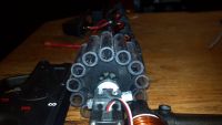
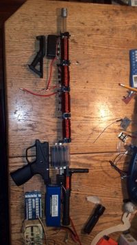
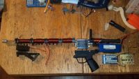
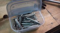
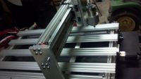


Re: V3 Coil Carbine
Maxwell, Thu Apr 25 2013, 01:46AM
Alright.
Can you provide a datasheet or link to the optical sensors you're using? I'm assuming if you're requesting a calibration that you have analog sensors. Are you hard-set on these? I am using two of these:

for benchtop chronograph timing and they work flawlessly...The arduino is simply looking for a 1 or 0 from the sensor (high/low)...I don't have any calibrations. Either the beam is broken or it is not. Granted, you need something a little narrower for fitting over the barrel.
Limits on max igbt on time for each stage
---> I've never had success with an IGBT and the arduino - from my understanding they're somewhat latching. If you know the controls behind triggering an IGBT on/off I can write a brief timer to control it.
Consecutive coil firing safety
---> This can be done by through circuitry - always grounded except when given signal.
Debounce each stage
---> Probably won't be necessary as everything is going to be digital.
One-shot trigger circuit
--->This is where we would use the digital de-bounce and code staging to record code status.
Switch selectable monostable or astable mode
--->I don't understand
Adjustable pulse length
--->Simple.
Drum Mag
I've never done servos. There are tons of Arduino libraries for servos...I've used stepper motors before which are easy. Are you looking for feedback to determine if a chamber is loaded or not with the IR reflection? Manual Jog shouldn't be an issue.
I don't see any problems with these requests.
Maxwell, Thu Apr 25 2013, 01:46AM
Alright.
Can you provide a datasheet or link to the optical sensors you're using? I'm assuming if you're requesting a calibration that you have analog sensors. Are you hard-set on these? I am using two of these:

for benchtop chronograph timing and they work flawlessly...The arduino is simply looking for a 1 or 0 from the sensor (high/low)...I don't have any calibrations. Either the beam is broken or it is not. Granted, you need something a little narrower for fitting over the barrel.
Limits on max igbt on time for each stage
---> I've never had success with an IGBT and the arduino - from my understanding they're somewhat latching. If you know the controls behind triggering an IGBT on/off I can write a brief timer to control it.
Consecutive coil firing safety
---> This can be done by through circuitry - always grounded except when given signal.
Debounce each stage
---> Probably won't be necessary as everything is going to be digital.
One-shot trigger circuit
--->This is where we would use the digital de-bounce and code staging to record code status.
Switch selectable monostable or astable mode
--->I don't understand
Adjustable pulse length
--->Simple.
Drum Mag
I've never done servos. There are tons of Arduino libraries for servos...I've used stepper motors before which are easy. Are you looking for feedback to determine if a chamber is loaded or not with the IR reflection? Manual Jog shouldn't be an issue.
I don't see any problems with these requests.
Re: V3 Coil Carbine
ben5017, Thu Apr 25 2013, 02:07AM
max:
I made the sensors out of a IR emitting diode and a IR phototransistor I got of mouser. I will supply the data sheet. They were working great when firing off of my old 2 stage 555 circuit. I am not set on anything but I think mine will do the job. (you have any experience using photodiodes? read they were much quicker)
---> I've never had success with an IGBT and the arduino - from my understanding they're somewhat latching. If you know the controls behind triggering an IGBT on/off I can write a brief timer to control it.
I am having the arduino controlling a igbt driver, not directly to the gate of the igbt. I will send you a link the that data sheet as well
Switch selectable monostable or astable mode
--->I don't understand
Semi auto or full auto
Are you looking for feedback to determine if a chamber is loaded or not with the IR reflection?
that was the plan. open to Ideas. maybe the encoder is the way to go
Re: V3 Coil Carbine
Maxwell, Wed May 01 2013, 05:57PM
Hi Ben5017,
While I'm working on this,
If you want to familiarize yourself with basic C++ code, the arduino notebook published at:

provides a lot of good background!
Maxwell, Wed May 01 2013, 05:57PM
Hi Ben5017,
While I'm working on this,
If you want to familiarize yourself with basic C++ code, the arduino notebook published at:

provides a lot of good background!
Re: V3 Coil Carbine
ben5017, Wed May 01 2013, 07:09PM
I will most defiantly check that out. BTW if you ever need any parts made, I would be more than happy too cut them out for you on my router, as a show of appreciation.. Just PM me.
ben5017, Wed May 01 2013, 07:09PM
I will most defiantly check that out. BTW if you ever need any parts made, I would be more than happy too cut them out for you on my router, as a show of appreciation.. Just PM me.
Re: V3 Coil Carbine
Maxwell, Thu May 09 2013, 12:44PM
Hi Ben,
I would anticipate having a functional code tomorrow afternoon.
For clarification again, which model arduino will you be working with?
Maxwell, Thu May 09 2013, 12:44PM
Hi Ben,
I would anticipate having a functional code tomorrow afternoon.
For clarification again, which model arduino will you be working with?
Re: V3 Coil Carbine
ben5017, Thu May 09 2013, 04:34PM
good stuff max, i plan on cutting the frame out this weekend too.
Im using a arduino mega 2560 for now. will probly switch it up to a smaller model as space is in short supply.
ben5017, Thu May 09 2013, 04:34PM
good stuff max, i plan on cutting the frame out this weekend too.
Im using a arduino mega 2560 for now. will probly switch it up to a smaller model as space is in short supply.
Re: V3 Coil Carbine
Maxwell, Wed May 15 2013, 02:28PM
Update: code does not function on my mega. (it does on my newer leonardo). But @Ben, no I haven't forgotten about you. Just de-bugging. I have a feeling that the interrupts I'm trying to call are not translating as I expected between boards.
The mega has more interrupt channels than does the other models.
However,
the code for the trigger, armature detection, firing works fine.
Re: V3 Coil Carbine
ben5017, Wed May 15 2013, 09:39PM
MAX: Sounds good. Here is a little more motivation. still got away to go .....
construction will be 5mm abs.
What is the most compact arduino you think I could get away with? I want to leave a little room for possible upgrades in the future.
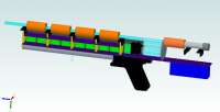
ben5017, Wed May 15 2013, 09:39PM
MAX: Sounds good. Here is a little more motivation. still got away to go .....
construction will be 5mm abs.
What is the most compact arduino you think I could get away with? I want to leave a little room for possible upgrades in the future.

Re: V3 Coil Carbine
Saz43, Mon May 20 2013, 06:21PM
Keep up the nice work, Ben! I'm really happy to see someone else activley working on building a serious portable coilgun. I'm looking forward to seeing more photos.
Saz43, Mon May 20 2013, 06:21PM
Keep up the nice work, Ben! I'm really happy to see someone else activley working on building a serious portable coilgun. I'm looking forward to seeing more photos.
Re: V3 Coil Carbine
Maxwell, Tue Jun 11 2013, 05:23PM
Hi Ben5017,
Apologies for the untimely compilation of this code.
With summer being here - free time is always sparse.
Regardless, here is the working code as mentioned.
Like I've mentioned previously I've never worked with Servos - so this will have to be a next-revision implementation to the code.
[code]
-Maxwell.[br]]06-11- 2013_maxwell.txt[/file]
Re: V3 Coil Carbine
Thomas W, Tue Jun 11 2013, 07:09PM

ive found these very good.
Thomas W, Tue Jun 11 2013, 07:09PM
ben5017 wrote ...
MAX: Sounds good. Here is a little more motivation. still got away to go .....
construction will be 5mm abs.
What is the most compact arduino you think I could get away with? I want to leave a little room for possible upgrades in the future.

MAX: Sounds good. Here is a little more motivation. still got away to go .....
construction will be 5mm abs.
What is the most compact arduino you think I could get away with? I want to leave a little room for possible upgrades in the future.


ive found these very good.
Re: V3 Coil Carbine
Maxwell, Wed Jun 12 2013, 12:12PM
For what Ben is doing, more digial I/O's are needed.
He already has one arduino Mega?
Maxwell, Wed Jun 12 2013, 12:12PM
For what Ben is doing, more digial I/O's are needed.
He already has one arduino Mega?
Re: V3 Coil Carbine
ben5017, Wed Jun 12 2013, 04:32PM
MAX: How do I access the code? What is the most compact arduino I can get away with? (how many I/O's do I need) I cannot find an acceptable way to use the mega in my gun. Its just to big. I will be using it for testing purposes.
ben5017, Wed Jun 12 2013, 04:32PM
MAX: How do I access the code? What is the most compact arduino I can get away with? (how many I/O's do I need) I cannot find an acceptable way to use the mega in my gun. Its just to big. I will be using it for testing purposes.
Re: V3 Coil Carbine
Maxwell, Wed Jun 12 2013, 07:26PM
The link the forum edited is misleading, but try this:

You should be able to get away with the micro if you're okay with the custom pinning. I would do a bunch of bench-testing with the code.
My code is set to work with the Leonardo...However I'm using 12 digital I/O pins...so serial may not work properly.
Maxwell, Wed Jun 12 2013, 07:26PM
The link the forum edited is misleading, but try this:

You should be able to get away with the micro if you're okay with the custom pinning. I would do a bunch of bench-testing with the code.
My code is set to work with the Leonardo...However I'm using 12 digital I/O pins...so serial may not work properly.
Re: V3 Coil Carbine
ben5017, Wed Jun 12 2013, 10:07PM
max,
You are awsome. this will save me so much startup time, and be great to reverse engineer to learn how to program these things. I will now be ordering a leonardo as well, its smaller than my mega and should fit with my updated gun layout.
ben5017, Wed Jun 12 2013, 10:07PM
max,
You are awsome. this will save me so much startup time, and be great to reverse engineer to learn how to program these things. I will now be ordering a leonardo as well, its smaller than my mega and should fit with my updated gun layout.
Re: V3 Coil Carbine
Maxwell, Thu Jun 13 2013, 02:35AM
FYI - debugging has already started:
" fire(50,SGRgC);
stage=stage+photogate(ptgB)+100; //stage should now equal 102+1+100=303
delayMicroseconds(50); //delay between coils (in us)"
The second ptgB should really be ptgC to reflect SGRgC above.
likewise in the statement right below it for SGRgD.
Re: V3 Coil Carbine
ben5017, Mon Jun 17 2013, 12:37AM
UPDATE: Frame close to completion. Router will be up and running this week, hopefully..
MAX: Keep it coming. You have no idea how much i appreciate you putting in the time to help me. A complete stranger no less.
hopefully the new pics will keep you interested in my project.
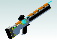
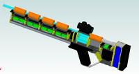


Re: V3 Coil Carbine
ben5017, Wed Jul 10 2013, 11:14PM
UPDATE: FRAME CUT AND 90% ASSEMBLED. SEE ATTACHED PICS OF THE FINAL CAD WORK, PICS OF THE REAL THING WILL FOLLOW SHORTLY ONCE I TAKE THEM!
TO DO LIST.
1) FINISH ATTACHING DRUM MAG
2) MAKE DRIVER AND SENSOR BOARDS
3) A LOT OF WIRING AND QUALITY SOLDERING TIME
4) AQUIRE PROGRAMMING SKILLS
5) PROFIT
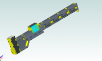
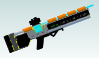
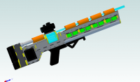
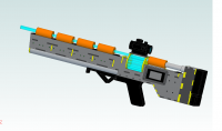


Re: V3 Coil Carbine
PSCG, Thu Jul 11 2013, 06:08AM
Really, a piece of art...keep up the awesome work!
Did you have any problems with the accelerator coils overheating when firing multiple shots?
PSCG, Thu Jul 11 2013, 06:08AM
Really, a piece of art...keep up the awesome work!
Did you have any problems with the accelerator coils overheating when firing multiple shots?
Re: V3 Coil Carbine
ben5017, Tue Jul 30 2013, 01:48PM
The accelerator coils are not on long enough to get even remotely close getting hot let alone overheating, the injector is another story. It is wound pretty aggressively and it alone will shoot the large projectiles over 10 feet! Which may be a little overkill.
ben5017, Tue Jul 30 2013, 01:48PM
The accelerator coils are not on long enough to get even remotely close getting hot let alone overheating, the injector is another story. It is wound pretty aggressively and it alone will shoot the large projectiles over 10 feet! Which may be a little overkill.
Re: V3 Coil Carbine
Yandersen, Wed Jul 31 2013, 09:55PM
Ben, where is the video?! Saz makes everybody vibrate in an extasy already - what are you waiting for?! %)
Yandersen, Wed Jul 31 2013, 09:55PM
Ben, where is the video?! Saz makes everybody vibrate in an extasy already - what are you waiting for?! %)
Re: V3 Coil Carbine
ben5017, Tue Oct 01 2013, 04:39PM
UPDATE:
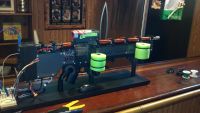
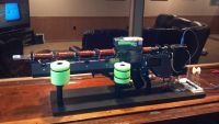
YANDERSON: VIDEO IS A WAYS AWAY, GOT A LOT OF WORK TO DO STILL..
HOWEVER, THE V3CC 95% MECHANICALLY COMPLETE
WAITING ON AN ENCODER TO FINISH THE FEED MECHANISM
ben5017, Tue Oct 01 2013, 04:39PM
UPDATE:


YANDERSON: VIDEO IS A WAYS AWAY, GOT A LOT OF WORK TO DO STILL..
HOWEVER, THE V3CC 95% MECHANICALLY COMPLETE
WAITING ON AN ENCODER TO FINISH THE FEED MECHANISM
Re: V3 Coil Carbine
ben5017, Tue Oct 01 2013, 04:42PM
EVEN MORE
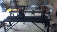
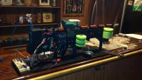
PICKED UP A 1940'S SHOP SMITH WHILE CLEANING OUT MY GRANDPA'S OLD BASEMENT THIS WEEKEND. PRETTY NICE SCORE ONCE I CLEANED HER UP A BIT. ESPECIALLY SINCE HE HAD ALL THE ATTACHMENTS.
ben5017, Tue Oct 01 2013, 04:42PM
EVEN MORE


PICKED UP A 1940'S SHOP SMITH WHILE CLEANING OUT MY GRANDPA'S OLD BASEMENT THIS WEEKEND. PRETTY NICE SCORE ONCE I CLEANED HER UP A BIT. ESPECIALLY SINCE HE HAD ALL THE ATTACHMENTS.
Re: V3 Coil Carbine
ben5017, Thu Oct 03 2013, 10:47PM
Having trouble getting my igbt's to turn fully on. 12Kohms? any suggestions? (ive tried a bunch of igbts with the same results). i am using tc422 drivers to energize the gate. The chip is turned on through my arduino mega
ben5017, Thu Oct 03 2013, 10:47PM
Having trouble getting my igbt's to turn fully on. 12Kohms? any suggestions? (ive tried a bunch of igbts with the same results). i am using tc422 drivers to energize the gate.
 The chip is turned on through my arduino mega
Re: V3 Coil Carbine
Saz43, Tue Oct 08 2013, 04:43PM
Nice work. Are you using any kind of load as you test the IGBTs? Try testing them with a resistor and LED as the load and see if it's different.
Saz43, Tue Oct 08 2013, 04:43PM
Nice work. Are you using any kind of load as you test the IGBTs? Try testing them with a resistor and LED as the load and see if it's different.
Re: V3 Coil Carbine
DerAlbi, Tue Oct 08 2013, 05:49PM
"Having trouble getting my igbt's to turn fully on. 12Kohms? any suggestions?"
What? 12Kohm relating to... what!? No schematic. No explaination.
The TC4422 is not verry robust concerning overvoltage if thats its output resistance its killed allready. Be carefull with that. What else could 12KOhm mean? Not the gate resistor, right?
If you used a 12K-Resistor on HV as a test load and the 12K are a wirewound resistor you probably be carefull with your IGBT.
if the 12K are... the hell... whats about 12K. WHERE?? any suggestions??
and btw: what means "fully" on to you? If you turn your IGBT on and measure the resistance between emitter and collector - depending on your multimeter the reading 12K makes sense, however you are testing bullshit.
Whats your Gatedrive voltage, whats your IGBT model, whats the values you expect, what did you measure.
Nice _mechanical_ work so far

Re: V3 Coil Carbine
ben5017, Wed Oct 09 2013, 12:30AM
12 Kohm between collector and emitter when gate voltage applied.
gate voltages used. 6 & 12 & 15 (when 6 didnt work)
do I need a resistor and/or diode between gate and emmitor?
IGBT: IXYS IGBT IXGN200N60A

(I wish they would tell you what the suffixes on the datasheet stand for)
By "on" I was looking for nearly no resistance (mohm) between collector and emitter. I had no trouble when driving the 422 off of a 555...
Saz: it does light up LED, I also tried my injector and nothing happened but a blown fuse after a second or so. there is to much resistance to get a magnetic field strong enough to move my bolt inside the injector.
ben5017, Wed Oct 09 2013, 12:30AM
12 Kohm between collector and emitter when gate voltage applied.
gate voltages used. 6 & 12 & 15 (when 6 didnt work)
do I need a resistor and/or diode between gate and emmitor?
IGBT: IXYS IGBT IXGN200N60A

(I wish they would tell you what the suffixes on the datasheet stand for)
By "on" I was looking for nearly no resistance (mohm) between collector and emitter. I had no trouble when driving the 422 off of a 555...
Saz: it does light up LED, I also tried my injector and nothing happened but a blown fuse after a second or so. there is to much resistance to get a magnetic field strong enough to move my bolt inside the injector.
Re: V3 Coil Carbine
DerAlbi, Wed Oct 09 2013, 01:35AM
ben... you are using IGBTs. not Mosfets.
why do you expect anything even close resistve behavior!?
...well small signal behavior suggests 17.8mOhm with 10V @ Gate. but YOU cant measure that.
What sufix do you mean? The "A" is descibed in the datasheet first page..................
Re: V3 Coil Carbine
Yandersen, Wed Oct 09 2013, 10:38AM
Funny, ben. The device you use rated 600V, 300A peak. The voltage drop is 2.5V. On digikey it costs $38.
Let's calculate the equivalent resistance of it when 300A conducted:
2.5V/300A = 8.3mOhm.
Now, the voltage rating of the switch must exceed the supply voltage 2 times. It means, that 100V rated device is good enough for you, ben.
So let's see what would be the MOSFET options. Here is the 100V rated MOSFET equivalent for $1:

Here is the 2 times better option for $4:

And 3 times better option for $7.4:

The MOSFETs linked are much smaller in size and have also lower driver's requirements then your IGBT. And unlike with the IGBT you can overload those higher then the pulse rating specifies given the pulse is shorter as MOSFETs do not latch. From the other hand, on low current the MOSFETS will show lower voltage drop while with IGBT you will always have 2.5V.
Yandersen, Wed Oct 09 2013, 10:38AM
Funny, ben. The device you use rated 600V, 300A peak. The voltage drop is 2.5V. On digikey it costs $38.
Let's calculate the equivalent resistance of it when 300A conducted:
2.5V/300A = 8.3mOhm.
Now, the voltage rating of the switch must exceed the supply voltage 2 times. It means, that 100V rated device is good enough for you, ben.
So let's see what would be the MOSFET options. Here is the 100V rated MOSFET equivalent for $1:

Here is the 2 times better option for $4:

And 3 times better option for $7.4:

The MOSFETs linked are much smaller in size and have also lower driver's requirements then your IGBT. And unlike with the IGBT you can overload those higher then the pulse rating specifies given the pulse is shorter as MOSFETs do not latch. From the other hand, on low current the MOSFETS will show lower voltage drop while with IGBT you will always have 2.5V.
Re: V3 Coil Carbine
Steve Conner, Wed Oct 09 2013, 10:53AM
An IGBT has a junction, so it doesn't have a Rds(on). It has an exponential voltage drop like an ordinary transistor, starting out about 0.5V for small currents and heading up logarithmically from there.
The lowest voltage rating of IGBT you can buy is something like 250V. Below 250V, MOSFETs work better.
Modern IGBTs are latchup free. One popular device is rated at 600V, 110A continuous, 300A pulsed at 25'c case temperature. In Tesla coil work we run it off a 320V DC bus and overload it to 450A or even 600 if you are feeling lucky. You would need a huge array of 600V MOSFETs to match this.
Re: V3 Coil Carbine
ben5017, Wed Oct 09 2013, 03:16PM
YAN: Don't use digi-key unless you have too. Kind of a rip off. FYI I got 20 of the IGBT's for 200$ on ebay.
from your math, I concluded my 12 Kohm is reasonable when only conducting the current of a single LED
2.5V/xA=12000ohm
x= .2 mA (for single LED)
(I could have sworn on my test setup when driving it off 555 & 422 that resistance was in mohm region with no load besides the multimeter??)
The reason I got higher voltage rated IGBT's (600v even though im powering my coils off of 24V) was to be able to withstand a larger voltage spike, allowing me to use more TVS diodes in series to kill the current as quickly as possible minimizing suck back.
STEVE: Can you explain further the significance of “Rds(on)†for a newbie and is my above reasoning correct?
Re: V3 Coil Carbine
DerAlbi, Wed Oct 09 2013, 05:10PM
ben, you are completely off. sorry for that. your 200$ are spent compeltely wrong.
this is a nightmare in a 24V-System to have IGBTs.
You obviously are not interested in how things work. This is why you kind of deserve that desaster. Just using google and reading about IGBTs would have helped. Yes even for a starter - Yes its work, Yes it hard. Yes is important.
You seem to look at a datasheet and every charactierized value you dont understand seems not existant for you. so you ignore e.g. Vcesat instead of googling it and this brings you here.
You hold your multimeter somewhere in the circuits and getting some values. what for?
You would be much better with simple IRF1404 using active clamping (or let the avalance in the body didoe take care of). Did you calculate wow fast the current decays if you allow 80V? Was the value really that bad?
"the higher the better", right? Sounds cooler at least -.-
And PLEASE stop measuring resistance over a transistor. its a completely stupid value. it tells you exactly nothing.
what bring you to this idea? can you explain how an IGBT work, and why it would be usefull to measure resstance between C and E ??
When you finally show your ultra hyper cool thing on youtube or be the biggest guy in town for your friends, will you mention that you dont even know how the thing works? -.-
"somethihg switching in there somehow maybe a bit for some time"
I will laugh if you loose all your coolnes when finally someone asks why you didnt use a potentiometer with a verry fast motor if you just put in variable resistances in your design...
Sorry for that. And: Rsd(on) is verry well documented by google.
look what i have found on the first few links after googling for "rsd(on) mosfet"

really cool, issnt it? Takes much less time than waiting for a forum answer too.
heeey and look what i found when googling for "mosfet versus igbt".
First link:
And you know... if sometimes the first link issnt satisfiying, maybe reading it will help too. The things you dont understand will cross you at your search many times and then - when reading enough - you will get a picture of how things work. there are also good youtube videos.
But yes, all this takes time. Time you will not be admired by your buddys for beeing the cooles guy with the hyper ultra electrical cannon that spits out a iron projectile.
if i tell you now that Rsd(on) is the resistive value of a mosfet between Soruce and Drain when its fully on, so that adding extra gatevoltage will not dreacease Vds anymore, you will get the meaning of Vds, but you miss the bigger picture that would help you really to understand things.
Vcesat is the same thing for Transistors. Its the Vce-Voltage that is reached as soon as the basis-current is high enough so that Vce will not decrease anymore. Your IGBT has a 2.5V Vcesat. So it doesnt mater much, how much current you apply you will always measure the voltage around 2.5V. Sometimes less, (low current) somtimes more (high current)
End this is why measruring resistance is useless. you always have something around 2.5V. So you apply 15V at the gate, and measure resistance with 10mA. you get 250Ohm, you measure it with 10A, you get 0.25Ohm. you use 100A... and so on.
Its always the same Transsitor. so what physical meaning has this resistnace??? NO MEANING AT ALL.
The onyl thing is certain: by using IGBTs you waste 2-3V of your Battery-Voltage in your IGBT. This is a expected loss >10%. This will lower your effective Voltage at the coils -> you need lower inductance -> less turns -> less force -> less speed.
This is why IGBTs are high voltage devices. 2.5V taken from 400V dont matter much.
READ. start at wikipedia, then search for Application notes. Then start with wikipedia again when you encoutner something you dont understand. Forums arent that effective to read, because the content is often shitty.
DerAlbi, Wed Oct 09 2013, 05:10PM
ben, you are completely off. sorry for that. your 200$ are spent compeltely wrong.
this is a nightmare in a 24V-System to have IGBTs.
You obviously are not interested in how things work. This is why you kind of deserve that desaster. Just using google and reading about IGBTs would have helped. Yes even for a starter - Yes its work, Yes it hard. Yes is important.
You seem to look at a datasheet and every charactierized value you dont understand seems not existant for you. so you ignore e.g. Vcesat instead of googling it and this brings you here.
You hold your multimeter somewhere in the circuits and getting some values. what for?
You would be much better with simple IRF1404 using active clamping (or let the avalance in the body didoe take care of). Did you calculate wow fast the current decays if you allow 80V? Was the value really that bad?
"the higher the better", right? Sounds cooler at least -.-
And PLEASE stop measuring resistance over a transistor. its a completely stupid value. it tells you exactly nothing.
what bring you to this idea? can you explain how an IGBT work, and why it would be usefull to measure resstance between C and E ??
When you finally show your ultra hyper cool thing on youtube or be the biggest guy in town for your friends, will you mention that you dont even know how the thing works? -.-
"somethihg switching in there somehow maybe a bit for some time"
I will laugh if you loose all your coolnes when finally someone asks why you didnt use a potentiometer with a verry fast motor if you just put in variable resistances in your design...
Sorry for that. And: Rsd(on) is verry well documented by google.
look what i have found on the first few links after googling for "rsd(on) mosfet"

really cool, issnt it? Takes much less time than waiting for a forum answer too.
heeey and look what i found when googling for "mosfet versus igbt".
First link:

And you know... if sometimes the first link issnt satisfiying, maybe reading it will help too. The things you dont understand will cross you at your search many times and then - when reading enough - you will get a picture of how things work. there are also good youtube videos.
But yes, all this takes time. Time you will not be admired by your buddys for beeing the cooles guy with the hyper ultra electrical cannon that spits out a iron projectile.
if i tell you now that Rsd(on) is the resistive value of a mosfet between Soruce and Drain when its fully on, so that adding extra gatevoltage will not dreacease Vds anymore, you will get the meaning of Vds, but you miss the bigger picture that would help you really to understand things.
Vcesat is the same thing for Transistors. Its the Vce-Voltage that is reached as soon as the basis-current is high enough so that Vce will not decrease anymore. Your IGBT has a 2.5V Vcesat. So it doesnt mater much, how much current you apply you will always measure the voltage around 2.5V. Sometimes less, (low current) somtimes more (high current)
End this is why measruring resistance is useless. you always have something around 2.5V. So you apply 15V at the gate, and measure resistance with 10mA. you get 250Ohm, you measure it with 10A, you get 0.25Ohm. you use 100A... and so on.
Its always the same Transsitor. so what physical meaning has this resistnace??? NO MEANING AT ALL.

The onyl thing is certain: by using IGBTs you waste 2-3V of your Battery-Voltage in your IGBT. This is a expected loss >10%. This will lower your effective Voltage at the coils -> you need lower inductance -> less turns -> less force -> less speed.
This is why IGBTs are high voltage devices. 2.5V taken from 400V dont matter much.
READ. start at wikipedia, then search for Application notes. Then start with wikipedia again when you encoutner something you dont understand. Forums arent that effective to read, because the content is often shitty.
Re: V3 Coil Carbine
ben5017, Wed Oct 09 2013, 06:01PM
Mostly fair enough. I am learning as I go, by the end of the project I will have a better grasp on how everything interrelates.
However I think "nightmare" is a little strong. I used the same IGBT's in my test rig with satisfactory results.
I will adjust my coil geometry to take into account the 2.5 voltage drop and still end up maxing out the pulse discharge of my lipo.
Re: V3 Coil Carbine
Yandersen, Wed Oct 09 2013, 07:53PM
Why don't you simply buy some MOSFETs instead? Can't spend extra $20 for more suitable devices? If your current is limited by the coils' resistance, then optimizing the speed of current decay by 600V is so nonsense...
Yandersen, Wed Oct 09 2013, 07:53PM
Why don't you simply buy some MOSFETs instead? Can't spend extra $20 for more suitable devices? If your current is limited by the coils' resistance, then optimizing the speed of current decay by 600V is so nonsense...
Re: V3 Coil Carbine
DerAlbi, Wed Oct 09 2013, 08:32PM
Well learning by making mistakes is ok so far. Even yan makes mistkes *troll*
If the results are ok for you then its fine. However keep in mind that there are other posibilities that dont require that much amount of money to achieve the same result OR spend the same amount and get even more "satisfactory" results. .... i must confess that even my charger costs more.
Have fun so far
Just a tip: if you spend your LiPo a big cap, maybe the voltage will not break down so much due to internal resistance so you can compensate some effects...
DerAlbi, Wed Oct 09 2013, 08:32PM
Well learning by making mistakes is ok so far. Even yan makes mistkes
 *troll*
If the results are ok for you then its fine. However keep in mind that there are other posibilities that dont require that much amount of money to achieve the same result OR spend the same amount and get even more "satisfactory" results. .... i must confess that even my charger costs more.
Have fun so far

Just a tip: if you spend your LiPo a big cap, maybe the voltage will not break down so much due to internal resistance
 so you can compensate some effects...
Re: V3 Coil Carbine
ben5017, Wed Oct 09 2013, 10:24PM
YAN: I probably will. Coil Inductance plays a larger role than resistance in limiting the current true?
any tips/ things to look out for when paralleling mosfets?
ALBI: Its all good. I just dont make the same mistake twice. + its not like i wont use the igbts for something ;) ,especially for the good deal I got. Mistakes are inevitable in my first serious electronics project. just hoping this will be the biggest one of the project.. (fingers crossed)
Re: V3 Coil Carbine
DerAlbi, Wed Oct 09 2013, 11:02PM
Current waveform is... fuck it. Not worth asking the question. its answered many times already. its all out there.
google: "inductor resistance current"
second link:
That was hard. i know.
Paralleling mosfets is not as complex as paralleling IGBTS. But really.. are you kidding me, that you wait for an answer here?
-> Google. "paralleling mosfets"
First hit:
Including causes of imbalance and solutions.
Boy... are you living in china? i think yahoo is capable of searching the internet too.
DerAlbi, Wed Oct 09 2013, 11:02PM
Current waveform is... fuck it. Not worth asking the question. its answered many times already. its all out there.
google: "inductor resistance current"
second link:

That was hard. i know.
Paralleling mosfets is not as complex as paralleling IGBTS. But really.. are you kidding me, that you wait for an answer here?
-> Google. "paralleling mosfets"
First hit:

Including causes of imbalance and solutions.
Boy... are you living in china? i think yahoo is capable of searching the internet too.
Re: V3 Coil Carbine
ben5017, Thu Oct 10 2013, 12:11AM
YOU ARE NOT FORCED TO READ/RESPOND TO MY POSTS
ben5017, Thu Oct 10 2013, 12:11AM
YOU ARE NOT FORCED TO READ/RESPOND TO MY POSTS
Re: V3 Coil Carbine
DerAlbi, Thu Oct 10 2013, 12:39AM
no, but how else to show you that you are better off with stopping to ignore all the answers to your questions. They are there. you are not doing anything fancy. its done before. many times. you struggle with basics. this is explained everywhere.
its mostly about using the keywords or alternative words of a question.
Its the most important thing to learn.. how to learn. trust me.
Re: V3 Coil Carbine
ben5017, Thu Oct 10 2013, 01:11AM
I told you this was my first serious electronics project I AM LEARNING THE BASICS. And I never claimed this project was "fancy". The project goals were to make something with my new cnc router, learn to program Arduino, and learn basic electronic design. By the end of the build , whenever that is I will have accomplished all 3
if you do not like my build YOU ARE NOT FORCED TO READ/RESPOND TO MY POSTS
Re: V3 Coil Carbine
DerAlbi, Thu Oct 10 2013, 02:22AM
how old are you?
DerAlbi, Thu Oct 10 2013, 02:22AM
how old are you?
Re: V3 Coil Carbine
Yandersen, Thu Oct 10 2013, 10:33AM
He is an American, Albi...
Easy, Benny. Learning can be done individually by using google and it is more efficient, fast and reliable then asking on forums. And learning cnc before understanding the basics of electronics is... seems to be the same nonsence as switching off coils at 600V having 24V for switch on. It is like building the cage of the gun having no guts solidly optimised... And so on.
As for MOSFETs, the devices you should have used instead of IGBT, the paralleling is as simple as putting the devices as close to each other as possible connecting the pins in parallel. But there are plenty of good 100V MOSFETs available which will perform perfectly alone (see my links again, or you can ask me to search digikey for you for the devices with required parameters).
"Coil Inductance plays a larger role than resistance in limiting the current true?"
Not in your design - you limit the current by coil's resistance, right? The speed of current rise is inversely proportional to inductance and proportional to applied voltage, which is the source voltage minus the voltage drop on the switch and minus the coil's resistance multiplied by current. So the higher the current, the slower it rises. When coils shut off, the speed of current fall is proportional to the zener voltage plus resistance*current - so resistance plays controversal here, see? As result, with 24V on input and 24V on zeners you will have current decaying faster then it was rising. That is why 600V is nonsence and 100V MOSFETs is the top devices for your application, even though 60V ones would be awesome too.
And BTW, as MOSFETs can handle higher pulse currents, you can achieve higher speed, but you need a cap in parallel to battery for that. Shorting the projectile and coils 2-3 times would let you achieve that as well as higher efficiency.
Re: V3 Coil Carbine
Steve Conner, Thu Oct 10 2013, 11:11AM
First of all...
Now onto the science... Coilguns are pretty inefficient so it hardly matters how you drive them in practice. But in theory, the most efficient way is probably to drive from a supply of several hundred volts and use IGBTs in an energy recovery scheme such as the diagonal half-bridge. You minimise suck-back by turning the drive off early and allowing the coil current to decay through the energy recovery circuit. If the coil resistance was negligible, you would shut the drive off when the projectile was about halfway in.
Try Barry's coilgun simulator to get a feel for the way things interact.
Steve Conner, Thu Oct 10 2013, 11:11AM
First of all...
site rules wrote ...
Part I: Behavior and Conduct
A. Be respectful. This includes everyone: other members of the forum, moderators and administrators, other people on the internet, and any other person, living or dead. Making false statements that are damaging to another person's reputation is not allowed. Insults, threats, and harassment are prohibited!
site rules wrote ...
Part II: Posting
B. Do your own research. If you intend to ask a question, please make sure it isn't already addressed in the archives, or on the wiki. Also, be sure to perform at least a cursory Google search. Remember, nobody wants to do your homework for you. Show some effort, and the community will repay you in kind.
Now onto the science... Coilguns are pretty inefficient so it hardly matters how you drive them in practice. But in theory, the most efficient way is probably to drive from a supply of several hundred volts and use IGBTs in an energy recovery scheme such as the diagonal half-bridge. You minimise suck-back by turning the drive off early and allowing the coil current to decay through the energy recovery circuit. If the coil resistance was negligible, you would shut the drive off when the projectile was about halfway in.
Try Barry's coilgun simulator to get a feel for the way things interact.
Re: V3 Coil Carbine
ben5017, Thu Oct 10 2013, 01:23PM
"He is an American, Albi..." And proud of it (albeit a little less lately.., say the last 5 yrs or so...)
I Forgot you Eastern Europeans are so superior to us westerners HAHAHA
-26 yrs old, I don't know why that matters but ill play along
ben5017, Thu Oct 10 2013, 01:23PM
"He is an American, Albi..." And proud of it (albeit a little less lately.., say the last 5 yrs or so...)
I Forgot you Eastern Europeans are so superior to us westerners HAHAHA
-26 yrs old, I don't know why that matters but ill play along
Re: V3 Coil Carbine
ben5017, Thu Oct 10 2013, 06:10PM
"He is an American, Albi..." And proud of it (albeit a little less lately.., say the last 5 yrs or so...)
I Forgot you Eastern Europeans are so superior to us westerners HAHAHA
-26 yrs old, I don't know why that matters but ill play along
ben5017, Thu Oct 10 2013, 06:10PM
"He is an American, Albi..." And proud of it (albeit a little less lately.., say the last 5 yrs or so...)
I Forgot you Eastern Europeans are so superior to us westerners HAHAHA
-26 yrs old, I don't know why that matters but ill play along
Re: V3 Coil Carbine
ben5017, Wed Sept 16 2015, 04:39PM
Worked on the V3 for the first time in months and finally have some performance data to share
Changed battery to 12s 3.7 AH lipo
performance data:
115 ft/s
32g slug
19j KE
drum mag is still work in progress
I am reading the encoder with the Arduino, but have not written the control code yet.
more updates to come when I find time to work on her some more.
Re: V3 Coil Carbine
DerAlbi, Wed Sept 16 2015, 06:09PM
Cool! Do you have an oscilloscope?
1) I would be interested in the battery voltage waveform during shot (AC coupled is ok)
2) how many working stages?
3) Fresh charged LiPo means 12*4.2V, right? ~50V That should give some pretty high current. Do you know how much (estimated)
4) how do you stop the projectile?
Re: V3 Coil Carbine
ben5017, Thu Sept 17 2015, 03:42AM

Here is a bit more data on the test firing.
Note: data point 5 on the charts are ESTIMATED values for a 5th stage.
I am encouraged by the linear nature of the performance data to consider squeezing a 5th stage on the V3.
Although it will be a considerable amount more work on a project that never ends.
ALBI:
-No scope. sorry. any recommendations?
-4 working stages, with no injector. I havnt had time to adjust the pulse length in the software so it blows its fuse with the higher volt batteries.
The coils used are the same ones I made and tuned for a 6s pack (82 ft/s).
Hopefully i can squeeze some more power out of her by winding new ones in the future
Maby a new goal of 25J muzzle energy could be possible...
ben5017, Thu Sept 17 2015, 03:42AM

Here is a bit more data on the test firing.
Note: data point 5 on the charts are ESTIMATED values for a 5th stage.
I am encouraged by the linear nature of the performance data to consider squeezing a 5th stage on the V3.
Although it will be a considerable amount more work on a project that never ends.
ALBI:
-No scope. sorry. any recommendations?
-4 working stages, with no injector. I havnt had time to adjust the pulse length in the software so it blows its fuse with the higher volt batteries.
The coils used are the same ones I made and tuned for a 6s pack (82 ft/s).
Hopefully i can squeeze some more power out of her by winding new ones in the future
Maby a new goal of 25J muzzle energy could be possible...
Re: V3 Coil Carbine
DerAlbi, Thu Sept 17 2015, 07:35AM
Recommendations for an Oscilloscope? Uhhm. Rigol DS1000Z-Series. but it costs 400$. (if that kind of money is too much, please tell me)
Its interesting how your kinetic energy rises linear while in my design the velocity rises linear - i dont know hoewever how long that trend will hold in my design due to current limitations. Your graph should break down too due to the same reason soon. The faster the projectrile get, the higher the acceleration power. So with the increasingly higher current the LiPos should draw a natural boundary somewhere.
5J per stage is impressive. I mean.. maybe not, because you cheat by having a heavy projectile... still double of my design with way lower voltages and much lower costs.
How long are your Coils and your projectile?
DerAlbi, Thu Sept 17 2015, 07:35AM
Recommendations for an Oscilloscope? Uhhm. Rigol DS1000Z-Series. but it costs 400$. (if that kind of money is too much, please tell me)
Its interesting how your kinetic energy rises linear while in my design the velocity rises linear - i dont know hoewever how long that trend will hold in my design due to current limitations. Your graph should break down too due to the same reason soon. The faster the projectrile get, the higher the acceleration power. So with the increasingly higher current the LiPos should draw a natural boundary somewhere.
5J per stage is impressive. I mean.. maybe not, because you cheat by having a heavy projectile...
 still double of my design with way lower voltages and much lower costs.
How long are your Coils and your projectile?
Re: V3 Coil Carbine
ben5017, Thu Sept 17 2015, 12:28PM
Thanks for the tip on the scope, I will give that one a look. I don't mind paying for a nice one.
Attached is a picture of the slug. they are modified solenoid cores. I ordered 50 of them (from Germany no less)
Only modification made was to cut of the back portion off.
Slugs are 68mm Lg.
Coil geometry:
12 ga. magnet wire, 75mm Lg.
Stage 1: 5 layers
Stage 2: 4 layers
Stage 3: 3 layers
Stage 4: 3 layers
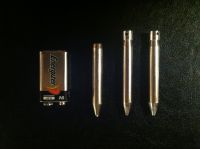

Re: V3 Coil Carbine
ben5017, Fri Sept 18 2015, 01:58AM
Some photos of my slug catcher. made from the 1.17mm stainless steel shell of a broken meat grinder.
Inside is lined with 1/2" thick rubber.
I had to start using a 3/4" thick mdf wear-plate on inside once i noticed the stainless was still denting even with the rubber.
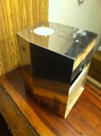
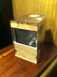
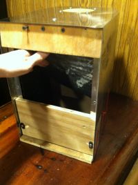
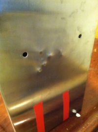


Re: V3 Coil Carbine
ben5017, Fri Sept 18 2015, 02:03AM
Since im in the posting mood, Here are some more recent photos of the V3
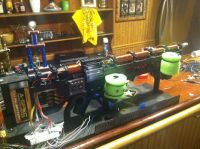
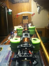
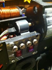
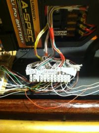
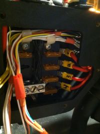
ben5017, Fri Sept 18 2015, 02:03AM
Since im in the posting mood, Here are some more recent photos of the V3


Re: V3 Coil Carbine
DerAlbi, Fri Sept 18 2015, 04:28AM
Quite some build how heavy?
Your energy density (Joules per acceleration length) is also interesting. You get 19.3J / (4*6.8cm)=0.71J/cm while in my design i achieve 1.43J/cm. So all my optimizations make it only twice as compact.
Not bad considering the coil geometry and beeing battery driven and so on.. nice!
Are those fuses for the coils? What is for coil behind the magazine or?
DerAlbi, Fri Sept 18 2015, 04:28AM
Quite some build
 how heavy?
Your energy density (Joules per acceleration length) is also interesting. You get 19.3J / (4*6.8cm)=0.71J/cm while in my design i achieve 1.43J/cm. So all my optimizations make it only twice as compact.

Not bad considering the coil geometry and beeing battery driven and so on.. nice!

Are those fuses for the coils?
 What is for coil behind the magazine or?
Re: V3 Coil Carbine
ben5017, Fri Sept 18 2015, 02:03PM
I cant remember the exact weight, will weigh it next time i get a chance to take it off its stand. (breadboard is attached to the stand for development so the V3 has not been off it for months) It was pretty heavy before upgrading the batteries (+400ish grams) & possibly adding a 5th stage... However the weight is well balanced & the front grip give additional stability, so its not to awkward to hold at all.
You are correct, the fuses (60 amp) are for the coils. Trying to protect from catastrophic failure.. After many f-ups in the development of the V3, they proved their worth already (have a box full of burnt ones... the 60 amp fuses will get your attention when they go...).
The coil behind the drum mag is the "injector" it is a homemade spring return solenoid that pushes the slug out of the drum.
I am planing on redesigning it to be much more compact, allowing me to move the drum towards the rear and should give me enough room to add a 5th stage.
Re: V3 Coil Carbine
DerAlbi, Sat Sept 19 2015, 03:24AM
Do you have any schematic on how you switch and what did you actually decide for? I hope you use mosfets at this voltage
The fuses surely blow spectacular if they do. They are not made for the high voltage.. if they melt they can sustain a spark that dissipates quite a lot of bang.
DerAlbi, Sat Sept 19 2015, 03:24AM
Do you have any schematic on how you switch and what did you actually decide for? I hope you use mosfets at this voltage

The fuses surely blow spectacular if they do. They are not made for the high voltage.. if they melt they can sustain a spark that dissipates quite a lot of bang.
Re: V3 Coil Carbine
ben5017, Thu Sept 24 2015, 01:14PM
Even after the success of recent upgrades, I am still not satisfied with the power of the V3. I am debating more radical changes to increase performance.
I have two options that would keep overall dimensions of the V3 the same but increase performance.
#1) stay with 12s (50 volts) and add 2 additional stages (cheaper/safer route)
#2) increase to 18s (75 volts) and add 1 additional stage (would need to buy different mosfets & tvs diodes and an additional 6s lipo)
Interested in hearing feedback from my fellow coil gunners on what option i should take. I believe #2 will give me biggest boost in KE, But not sure it will be worth extra expense/weight
Additional changes that will be made
Change 1) gear motor/encoder drum mag is replaced with a direct drive stepper motor. this configuration is more compact and should be easier to program and integrate on the arduino.
Change 2) Injector is removed and replaced by a full stage coil (one of the additional stages mentioned above) directly in front of the drum mag. this coil will be pulse length controlled by the arduino to pull the projectile out of the drum and will act as the first accelerator stage.
-Albi no schematic to post right now sorry. 100v 420 amp mosfets were used. driven by 12V 1.2A gate drivers tc422 series (mouser# off top of my head). Gate driver gets 5 volt signal directly from arduino mega.
Re: V3 Coil Carbine
DerAlbi, Thu Sept 24 2015, 08:29PM
Increasing voltage will not necessarily increase performance. It may increase the current slightly, but that may only cause deeper saturations.. so not *much* gained. Your LiPos will have a current limit and having more in series only increases the chance of having a bad one in series and that will ultimately limit the current. Even if all LiPos are fine, its not the voltage that transfers the power, its the current...
The only way to get away with higher voltage is to also increase turn-count in your coils. This will lower the current but keep the turns*current constant.
That would be totally fine then, but it wont increase your power transfer.. it basically would just increase the LiPo lifetime due to lower peak current.
Increasing the stages would be the way to go. But you have to check, if you can do that actually (with a proportional energy increase). The faster the projectile gets, the more power (current*voltage) must be provided or in other words: the same energy, but shorter time.
As i see the current in your design as a limiting factor it might be that the additional stage wont push as much energy as the 2nd or 3rd stage.
It really sucks, that you cant do a good measurements currently (how is the oscilloscope going? ).. it would be really beneficial to see how close your LiPos are allready to dying to get some starting point for a debate thats more based on facts instead of fear and believe. So currently i just can give you my opinion based on gut feeling..
If no schematic, can you tell me the topology? Have you used a Halfbdige, or do you use the typical reverse diode across the coil?
DerAlbi, Thu Sept 24 2015, 08:29PM
Increasing voltage will not necessarily increase performance. It may increase the current slightly, but that may only cause deeper saturations.. so not *much* gained. Your LiPos will have a current limit and having more in series only increases the chance of having a bad one in series and that will ultimately limit the current. Even if all LiPos are fine, its not the voltage that transfers the power, its the current...
The only way to get away with higher voltage is to also increase turn-count in your coils. This will lower the current but keep the turns*current constant.
That would be totally fine then, but it wont increase your power transfer.. it basically would just increase the LiPo lifetime due to lower peak current.
Increasing the stages would be the way to go. But you have to check, if you can do that actually (with a proportional energy increase). The faster the projectile gets, the more power (current*voltage) must be provided or in other words: the same energy, but shorter time.
As i see the current in your design as a limiting factor it might be that the additional stage wont push as much energy as the 2nd or 3rd stage.
It really sucks, that you cant do a good measurements currently (how is the oscilloscope going?
 ).. it would be really beneficial to see how close your LiPos are allready to dying to get some starting point for a debate thats more based on facts instead of fear and believe. So currently i just can give you my opinion based on gut feeling..
If no schematic, can you tell me the topology? Have you used a Halfbdige, or do you use the typical reverse diode across the coil?
Re: V3 Coil Carbine
ben5017, Mon Sept 28 2015, 12:34PM
Good points albi. (BTW I plan on ordering a scope this week)
I am using paralled bi-directional tvs diodes for clamping
I have decided to stay on 12s and add 2 stages.
I got most of the modifications roughed out on CAD this weekend.
Removed the fuse box and the injector, replaced gear motor/encoder with a stepper motor, This allowed the drum mag to be moved back enough to fit 2 more stages with only increasing overall length an additional 3/8"
Re: V3 Coil Carbine
Yandersen, Tue Sept 29 2015, 08:56AM
Ben, paralleling TVS is not good - due to a variance in breakdown voltage most of the power may be dissipated by the TVS with lowest BD voltage. Better to put TVS with smaller breakdown voltages in series.
I also do not agree with Albi about the batteries. The more cells you put in series the better, but the coils must be rewound as well - more turns with thinner wire. After all, your input power is U*I, and it is better to aim for higher U. The pull force is I*turns, therefore the more turns the coil has the better, but you need more U to ensure that current can rise fast enough.
Re: V3 Coil Carbine
DerAlbi, Tue Sept 29 2015, 12:02PM
Nice form of disagreement. Just repeat, what i say

DerAlbi, Tue Sept 29 2015, 12:02PM
Nice form of disagreement. Just repeat, what i say

The only way to get away with higher voltage is to also increase turn-count in your coils. This will lower the current but keep the turns*current constant.

Re: V3 Coil Carbine
ben5017, Tue Sept 29 2015, 02:39PM
Yan,
Thanks for the heads up on the TVS diodes. Makes perfect sense after you educated me. I will be ordering new ones this week.
I am interested to see what gains in performance i can make after rewinding better and tighter(with epoxy) coils and tuning them for the new 50v setup.
(performance numbers given on previous page were using same loose and sloppy coils i made & tuned for 25v. With Delta KE of approx 5j/STAGE)
Even an increase in KE/stage of 10% would add up, especially with additional 2 stages.
30j KE might be possible
Re: V3 Coil Carbine
DerAlbi, Tue Sept 29 2015, 04:04PM
I think you should wait until you get the oscilloscope to measure if/how your swtiching and everything works on your setup right now. I think if you really do the effort to rewind the coils you should maximize the learning effect. That works best if you do good before- and after-measurements.
(for some reason i dont believe that TVS are really effective at such currents, since they absorb the energy.. but not in such orders..., yeah.. i know.. thats not based on facts.. sry)
Re: V3 Coil Carbine
ben5017, Tue Sept 29 2015, 04:31PM
Albi,
I agree. Should have the scope here in a couple weeks. Might as well get one while my electronics are still in breadboard stage..
Remaking the coils will be the last upgrade done once it is shooting consistent with 6 stages.
I still have to modify the v3 frame and cut new pieces on router. + additional electronics and coding for 2 more stages + stepper motor control.
It will be a good bit before I focus on tuning coils.
As far as the TVS diodes, I have put around 2-3 hundred rounds through with no issues. However I am always open for ways to improve my design.
Re: V3 Coil Carbine
ben5017, Thu Oct 01 2015, 12:54AM
Started drawing up the modifications for the V3 mark 2.
First pic shows what I will be reusing once I get done removing the back half.
Last 2 pics show 2 possible configurations for the mark 2
I can either
1) add two more stages with coils using similar geometry currently used and shown measured approx 5j/stage
2) split coils in half for a total of 12 shorter stages. I have the room for the extra FETs would just be alot more work.
I could use the arduino to play with the timing and sequencing to have multiple coils on at the same time for more of a rolling mag field.
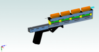


Re: V3 Coil Carbine
Yandersen, Fri Oct 02 2015, 06:44PM
Uh, I love that last option. :) Though the shorter the coils the more precise the triggering must be and you will have to deal with higher currents which is not good considering your choosed a battery power supply. Better to maximize the length of the barrel and use the same long coils.
There is no way a battery-powered gun can be efficient, so don't bother about it and aim for light weight and rapid fire to compensate this disadvantage.
And I really don't like your reloading mechanism - it's a bulky solution. Why not using a conventional spring-pushed ammo holder with magnetic plunger to push out projectiles? It can store more ammo, feed it faster, require less space and eliminates a need for a rotation motor.
And a quick tip in case you will go with longer barrel - you may need a cap on the far end of it. The longer the power rails the higher the voltage swing could be due to their increased inductance.
Re: V3 Coil Carbine
BigBad, Sat Oct 03 2015, 03:25AM
Yes, last one looks good to me too.
Short, fat coils often tend to work well.
BigBad, Sat Oct 03 2015, 03:25AM
Yes, last one looks good to me too.
Short, fat coils often tend to work well.
Re: V3 Coil Carbine
DerAlbi, Sat Oct 03 2015, 10:10AM
Depends ons what "well" means. In a coilgun its ususally equivalent to good efficiency. Since he uses Batteries, he does not care about that. I am with Vandersen here.
I optimized my coil switchting to maximize the figure of merit "Ekin*Eff^2".
A Battery design does not need that. He can purely optimize Ekin.
Re: V3 Coil Carbine
BigBad, Sat Oct 03 2015, 03:13PM
Well, long coils give poorer thrust, short, pancake style coils give higher resistance and are heavier (unless you turn several on at once in parallel).
Coils where the length is equal to the winding thickness which is equal to the aperture size seem to do the best.
BigBad, Sat Oct 03 2015, 03:13PM
Well, long coils give poorer thrust, short, pancake style coils give higher resistance and are heavier (unless you turn several on at once in parallel).
Coils where the length is equal to the winding thickness which is equal to the aperture size seem to do the best.
Re: V3 Coil Carbine
Yandersen, Mon Oct 05 2015, 01:56AM

Short coils (length==winding_thickness) have the highest L/R ratio, therefore have lowest possible heat dissipation per energy stored. This makes short coils ideal for recuperational designs, which is not the case.
To maximize the pull force per energy stored, one should tend to minimize the OD to squeeze all of the produced flux as close to the projectile as possible - the further a turn from projectile the less it pulls (smaller portion of it's flux is inside the barrel) and the more this turn will dissipate (longer wire).
First, Ben, you should determine the OD of your coils. Use FEMM. Make a coil with one turn and constant current (as much as your battery able to supply) and gradually increase the radius of that turn, writing down the pull force and wire resistance. From those two graphs you will be able to tell how far from the barrel the external layer of a coil can be to make a reasonable ratio of pull force per wire resistance (the wider the turn the higher it's resistance and lower the pull force).
The length of your coils should be at least equal to ID. If you can make a lot of such small coils - it is good. To choose the right wire thickness, set the constant current and gradually increase turns number: see when the projectile starts to saturate (2.2T at the tip of the projectile). Then calculate which wire thickness you need to make the required number of turns fit into the chosen coil geometry.
Yandersen, Mon Oct 05 2015, 01:56AM

Short coils (length==winding_thickness) have the highest L/R ratio, therefore have lowest possible heat dissipation per energy stored. This makes short coils ideal for recuperational designs, which is not the case.
To maximize the pull force per energy stored, one should tend to minimize the OD to squeeze all of the produced flux as close to the projectile as possible - the further a turn from projectile the less it pulls (smaller portion of it's flux is inside the barrel) and the more this turn will dissipate (longer wire).
First, Ben, you should determine the OD of your coils. Use FEMM. Make a coil with one turn and constant current (as much as your battery able to supply) and gradually increase the radius of that turn, writing down the pull force and wire resistance. From those two graphs you will be able to tell how far from the barrel the external layer of a coil can be to make a reasonable ratio of pull force per wire resistance (the wider the turn the higher it's resistance and lower the pull force).
The length of your coils should be at least equal to ID. If you can make a lot of such small coils - it is good. To choose the right wire thickness, set the constant current and gradually increase turns number: see when the projectile starts to saturate (2.2T at the tip of the projectile). Then calculate which wire thickness you need to make the required number of turns fit into the chosen coil geometry.
Re: V3 Coil Carbine
DerAlbi, Mon Oct 05 2015, 07:57PM
I am with Yan at this one. Tighter turns have more coupling, so optimizing L/R is not the right thing in a system thats not efficiency bound.
However for me it begs the question:
if the short fat (lets call it Albi ) coil is most efficient, does it means that the tranfered power is relatively large?
I mean.. what is efficiency? Is it lowest loss at low energy transer? Or is it highes energy transfer while having high loss? It both represents best efficiency.
Or in other words again: how can a coil be efficient if it does not transfer the maximum of energy?
DerAlbi, Mon Oct 05 2015, 07:57PM
I am with Yan at this one. Tighter turns have more coupling, so optimizing L/R is not the right thing in a system thats not efficiency bound.
However for me it begs the question:
if the short fat (lets call it Albi
 ) coil is most efficient, does it means that the tranfered power is relatively large?
I mean.. what is efficiency? Is it lowest loss at low energy transer? Or is it highes energy transfer while having high loss? It both represents best efficiency.
Or in other words again: how can a coil be efficient if it does not transfer the maximum of energy?
Re: V3 Coil Carbine
Yandersen, Tue Oct 06 2015, 06:42AM
Hm, the term "coil efficiency" may be linked to a ratio of Pull_force/Heat_dissipation, or
n=F/P
Few thoughts:
1) Up to a saturation point we have force and heat dissipation proportional to the square of the current: F~I^2. After the saturation force tend to be linearly proportional to the current. Conclusion: coil's efficiency does not depend on current before the saturation, but drops after.
2) Coil's resistance linearly depends on coil's length, therefore heat dissipation does too. But force doesn't - increasing the coil's length adds turns which are further and further away from the projectile resulting in lower pull force they produce. Conclusion: the longer the coil the less it is efficient.
3) This one is obvious - the faster the projectile goes, the more efficient coil is:
Apull=F*v,
Aheat=P*t,
therefore the faster the projectile passes the coil, the less heat will be dissipated.
Conclusion: shorter projectiles are accelerated faster, therefore lead to a higher efficiency.
Re: V3 Coil Carbine
ben5017, Thu Apr 28 2016, 01:09PM
I decided to take what i learned from the v3 and go for a compltet redesign i am calling it the V3 MARK2
Not sure whether to start a dedicated new thread or just keep rolling with this one.
I Took the same design as the V3, Which had 4+1 Stages and 18J KE
, and designed the Mark 2 with 12 stages, and a new goal of 40J KE (which would be a nice even 50m/s)
Here is a quick sneak peak of my progress (updates and edits to follow)
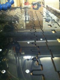
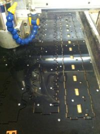
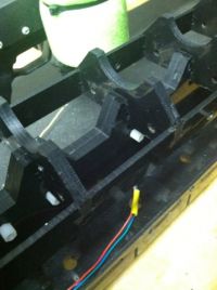
Pics of the molding process i used to make the iron matrix sensor housings
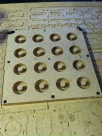
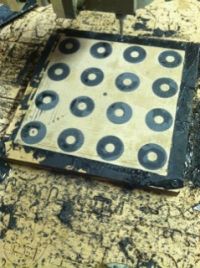
After the epoxy hardened, i cut out the inner diameter and outter diameter then cut the bottoms flush with a jig attached to my router
Finished: Iron Matrix sensors
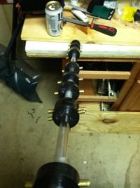
I scrapped the servo/encoder setup used in the V3 and replaced with a timing belt and stepper motor.
Shown below ate the drum mag bearing and belt tensioner setup
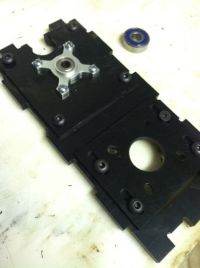
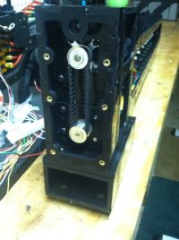
Next, I 3d printed the mounting system for the pistol grip
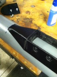
Next up was to make a coil winder:
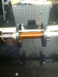
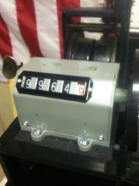
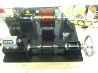
TEST COILS FOR TUNING
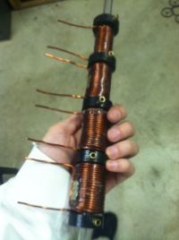
SPACE FOR CIRCUITS:
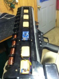
I will try to post some better pictures tonight when I get home. These were just the ones i had on my phone at the moment.
ben5017, Thu Apr 28 2016, 01:09PM
I decided to take what i learned from the v3 and go for a compltet redesign i am calling it the V3 MARK2
Not sure whether to start a dedicated new thread or just keep rolling with this one.
I Took the same design as the V3, Which had 4+1 Stages and 18J KE
, and designed the Mark 2 with 12 stages, and a new goal of 40J KE (which would be a nice even 50m/s)
Here is a quick sneak peak of my progress (updates and edits to follow)


Pics of the molding process i used to make the iron matrix sensor housings


After the epoxy hardened, i cut out the inner diameter and outter diameter then cut the bottoms flush with a jig attached to my router
Finished: Iron Matrix sensors

I scrapped the servo/encoder setup used in the V3 and replaced with a timing belt and stepper motor.
Shown below ate the drum mag bearing and belt tensioner setup


Next, I 3d printed the mounting system for the pistol grip


Next up was to make a coil winder:


TEST COILS FOR TUNING

SPACE FOR CIRCUITS:

I will try to post some better pictures tonight when I get home. These were just the ones i had on my phone at the moment.
Re: V3 Coil Carbine
DerAlbi, Fri Apr 29 2016, 02:43AM
!amazed Wohooooooooooooo
 That mechanical design!
  That awesomeness.
  That tooling!
Is that a stepper motor and revolver reload mechanism?
Any idea how heavy that will become? I guess its around 8kg in the end?
What dimensions?
A 32g projectile that slow with so much energy... how will you catch the projectiles while test shooting?
What worries me:
a) Your turn count. You counter did count negative. Now the gun will shoot backwards
b) where are the switches?
c) i dont know what a Iron Matrix sensor is
d) with increasing speed, have you considered supporting your poor battery with some capacitors? If you have an oscilloscope, i would loooove to see the voltage of the pack during a shot. (any thoughts on how much current the last stage will have?)
DerAlbi, Fri Apr 29 2016, 02:43AM
!amazed Wohooooooooooooo

 That mechanical design!
  That awesomeness.
  That tooling!
Is that a stepper motor and revolver reload mechanism?
Any idea how heavy that will become? I guess its around 8kg in the end?
What dimensions?
A 32g projectile that slow with so much energy... how will you catch the projectiles while test shooting?
What worries me:
a) Your turn count. You counter did count negative. Now the gun will shoot backwards

b) where are the switches?
c) i dont know what a Iron Matrix sensor is

d) with increasing speed, have you considered supporting your poor battery with some capacitors? If you have an oscilloscope, i would loooove to see the voltage of the pack during a shot. (any thoughts on how much current the last stage will have?)
Re: V3 Coil Carbine
Karmaslap, Fri Apr 29 2016, 04:29AM
I'm also quite curious what the iron matrix sensors are. Are they just iron end caps with optical senslrs embedded in them?
I read this thread in high school (2012) when you started and it's one of the threads thst got me interested in making my own gun, so I am looking forward to more updates! Beautiful mechanical work
Re: V3 Coil Carbine
ben5017, Fri Apr 29 2016, 12:33PM
CAD model used to design the V3 Mark 2
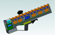
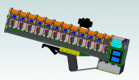
Some overall Photos, It all fit together perfectly
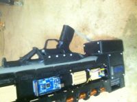
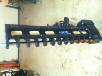
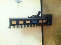
Albi: 8-10 Kg is probly a good ballpark range, depending on final coil sizes.
It is comfortable to hold and handel with a good solid pistol grip and front grip. Being a Bulpup design, the overal weight distribution is pretty even along the length, it is not awkward at all to handle so that makes weight a little more manageable. I may add a strap in the future, we will see once she is nearer to completion
-Drum is driven by a stepper motor and timing belt.
-overall length is 32" (will update dims when i get home)
-Slug catching setup is shown on previous page.
-Iron matrix sensor housings are simply iron powder suspended in epoxy (1/2" thick). I saw the name somewhere and liked it so i stole it :) i am Not sure if they will be worth the effort it took to make them though... (on barrys coil gun site he showed promising results using the iron matrix end caps on his low voltage coilgun albeit on a less powerfull setup., only one way to find out.....)
-Thanks for reminding me about the turn counter being backwards.... It never even crossed my mind that the rotation would be reversed when driving it off of 2 wheels like i did. I was pissed first time i used it. Idiot.
ben5017, Fri Apr 29 2016, 12:33PM
CAD model used to design the V3 Mark 2


Some overall Photos, It all fit together perfectly


Albi: 8-10 Kg is probly a good ballpark range, depending on final coil sizes.
It is comfortable to hold and handel with a good solid pistol grip and front grip. Being a Bulpup design, the overal weight distribution is pretty even along the length, it is not awkward at all to handle so that makes weight a little more manageable. I may add a strap in the future, we will see once she is nearer to completion
-Drum is driven by a stepper motor and timing belt.
-overall length is 32" (will update dims when i get home)
-Slug catching setup is shown on previous page.
-Iron matrix sensor housings are simply iron powder suspended in epoxy (1/2" thick). I saw the name somewhere and liked it so i stole it :) i am Not sure if they will be worth the effort it took to make them though... (on barrys coil gun site he showed promising results using the iron matrix end caps on his low voltage coilgun albeit on a less powerfull setup., only one way to find out.....)
-Thanks for reminding me about the turn counter being backwards.... It never even crossed my mind that the rotation would be reversed when driving it off of 2 wheels like i did. I was pissed first time i used it. Idiot.
Re: V3 Coil Carbine
ben5017, Tue Feb 07 2017, 05:30PM
Bus bars made and installed.
Lots more to do, updates to come.
MAGA
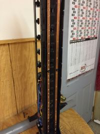
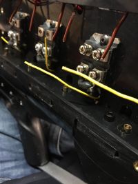
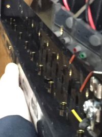
ben5017, Tue Feb 07 2017, 05:30PM
Bus bars made and installed.
Lots more to do, updates to come.
MAGA


Re: V3 Coil Carbine
Saz43, Wed Feb 08 2017, 06:39AM
Hey nice work!
Saz43, Wed Feb 08 2017, 06:39AM
Hey nice work!
Re: V3 Coil Carbine
DerAlbi, Thu Feb 09 2017, 10:33PM
It worries me is how fast your turn count decays.... i dont see much turns left for the last few coils... whats your plan about this ?
DerAlbi, Thu Feb 09 2017, 10:33PM
It worries me is how fast your turn count decays.... i dont see much turns left for the last few coils... whats your plan about this ?
Re: V3 Coil Carbine
ben5017, Fri Feb 10 2017, 04:00AM
Coils you see are arbitrary, I will determine final coil geometry through testing. plan is to optimize KE from the first stage alone, then work my way down from there.
picked up a new toy. Now i just have to figure out how to use it.
ben5017, Fri Feb 10 2017, 04:00AM
Coils you see are arbitrary, I will determine final coil geometry through testing. plan is to optimize KE from the first stage alone, then work my way down from there.
picked up a new toy. Now i just have to figure out how to use it.

Re: V3 Coil Carbine
DerAlbi, Fri Feb 10 2017, 06:32AM
I have that one too. Usage is a little frustrating because i allways move the rotary knob while pushing it. The UI is deeply structured because those small form factor scopes just dont have enough knobs for everything. Is it already cranked up to 100MHz ? ^_^
DerAlbi, Fri Feb 10 2017, 06:32AM
I have that one too. Usage is a little frustrating because i allways move the rotary knob while pushing it. The UI is deeply structured because those small form factor scopes just dont have enough knobs for everything. Is it already cranked up to 100MHz ? ^_^
Print this page

