MOT full wave rectification and grounding problems
PhilGood, Sun Jul 22 2012, 12:21AMWhen full wave rectifiying a MOT output, the problem is we cannot ground the -HV rail because one of secondary's end is already grounded.
The best solution is to use a MOT which secondary is not grounded, but they are quite rare and hard to find.
Another solution would be to leave the -HV floating, but this is not really recommended for a Tesla Coil.
Steve, you suggested a solution that sounds really great :
Steve Conner wrote ...
The solution is to use a voltage doubler. Then you can ground both the core and the negative output. Indeed that is why MOTs have one end of the secondary connected to the core, because they are designed for use with a doubler.
You get twice the output voltage, which you may not want, but you can fix that by reducing the input voltage to 120V.
You also have halfwave rectification, but you can fix that by using two MOT/doubler arrangements 180 degrees out of phase. (and maybe connect the primaries in series for 240V operation?)
But after drawing the schematic I'm like ... hmm there might be something wrong here...The solution is to use a voltage doubler. Then you can ground both the core and the negative output. Indeed that is why MOTs have one end of the secondary connected to the core, because they are designed for use with a doubler.
You get twice the output voltage, which you may not want, but you can fix that by reducing the input voltage to 120V.
You also have halfwave rectification, but you can fix that by using two MOT/doubler arrangements 180 degrees out of phase. (and maybe connect the primaries in series for 240V operation?)
This is how I understand I should connect the two MOT/doubler arrangements:
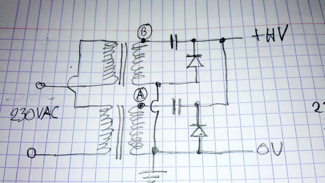
Well ok the two voltage doublers outputs are at the same average potential.
What bothers me is at a said time at peak voltage, the two non-grounded secondaries outputs (A and B) have a voltage difference of 2x peak voltage between them, and are connected together thru two series capacitors, one of them being discharged and the other one charged at Vpeak. This means the two series capacitors would share 3x Vpeak, 1.5x Vpeak each. Next half cycle they would share 2x + 1.5x Vpeak..and so on ...total voltage accross the two series capacitors would keep increasing by 1/2 Vpeak each half cycle... ?
[EDIT]
- hmm... folowing my weird logic, voltage seen across the two series capacitors would not increase indefinitely but would tend to 4x Vpeak, so each capacitor would be charged at 2x Vpeak, and the output voltage would be 3x Vpeak
[/EDIT]
There's probly something wrong in my circuit, or in my way of thinking (or both ? lol). Please help, I'm a bit lost here...
PS: We could also connect the two MOTs primaries in parallel out of phase, and connect the secondaries like a classic full wave rectifier for center-tapped transformer, but each MOT would still work in half wave rectification mode and suffer from core saturation.
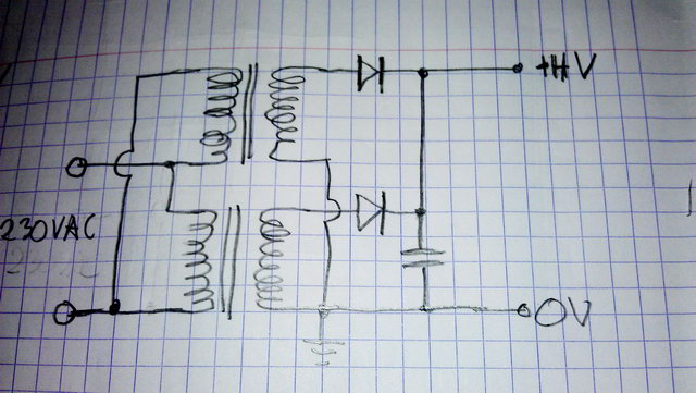
(sorry for the quick hand-drawn schematics)
Re: MOT full wave rectification and grounding problems
Dr. Dark Current, Sun Jul 22 2012, 09:04AM
In the "dual doubler" circuit you forgot a diode in series with each of the doubler outputs and the +HV rail. However the power available from such setup will be quite low, lower than full wave rectifying one MOT.
Another possibility is to just use a full wave rectifier and not ground anything. Then you will need to use a filament transformer with enough interwinding isolation, but with a split plastic bobbin and a large enough core this is quite easily doable.
Re: MOT full wave rectification and grounding problems
PhilGood, Sun Jul 22 2012, 10:01AM
Oh, this is an easy fix to my problem ! Thanks Dr. DC
<-- needs some sleep
But why would the dual doubler arrangement deliver less power than one full wave rectified MOT ? Would it be better if I increase capacitance of each doubler to 3 or 4 µF ?
I was thinking to let the -HV floating... but this power supply is meant to run an HFVTTC with this circuit :
is it safe to have the -HF floating on such a coil ... would it decrease it's performances ?
Would a 1 square meter copper sheet set on the ground one meter below the coil be ok as counterpoise and RF ground instead of connecting -HV to mains ground ?
(Sorry for the drift, I should have posted this in TC's section)
PhilGood, Sun Jul 22 2012, 10:01AM
Oh, this is an easy fix to my problem ! Thanks Dr. DC

<-- needs some sleep
But why would the dual doubler arrangement deliver less power than one full wave rectified MOT ? Would it be better if I increase capacitance of each doubler to 3 or 4 µF ?
I was thinking to let the -HV floating... but this power supply is meant to run an HFVTTC with this circuit :
is it safe to have the -HF floating on such a coil ... would it decrease it's performances ?
Would a 1 square meter copper sheet set on the ground one meter below the coil be ok as counterpoise and RF ground instead of connecting -HV to mains ground ?
(Sorry for the drift, I should have posted this in TC's section)
Re: MOT full wave rectification and grounding problems
Dr. Dark Current, Sun Jul 22 2012, 11:01AM
It would deliver less power because the transformers run at 1/2 voltage so the power available with the same relative voltage drop is 4 times as low. With 2 transformers this is 2 times lower than a single transformer running full power.
I think it is a bad idea to use anything else than the capacitor the transformer originally ran with, because the transformer's leakage inductance and the capacitnace form a tuned circuit which is tuned for maximum power output and good power factor.
In that circuit, you must not let the supply float, but RF-couple it to a ground. This can be done with a small (few nF) capacitor from the -V rail to RF ground. You can still use the metal plate as a RF ground, but connect it through a high-value resistor and/or inductor to mains Earth, so it will not kill you when you touch it.
Re: MOT full wave rectification and grounding problems
Steve Conner, Sun Jul 22 2012, 11:34AM
Yes you need another 2 diodes as Dr. DC says.
My idea gives less output power, but it also operates the MOTs at half the flux density, so they can be run for longer without overheating. I originally thought it up as a cheap power supply for a tube radio transmitter or similar.
You can use any size of capacitor, not just the one that came out of the oven. The bigger it is, the less the output voltage will sag under load. I've used series strings of electrolytics.
Re: MOT full wave rectification and grounding problems
PhilGood, Sun Jul 22 2012, 11:49AM
Thanks again Dr. DC for the explanation, it makes almost everything clear.
The only thing I don't get is the connection between my metal plate and mains earth.
I use a serie capacitor to connect my -HV rail to my metal plate in order to block DC.
So I have only RF on my metal plate. And I don't want that because my feet are resting on that metal plate !
Shouldn't I use another capacitor to divert this RF into mains earth ?
A high value inductance would block RF and prevent it to flow into mains earth, right ?
And for the resistor option, what value range (and power) would you use for such setup ? Would this high value resistor be efficient enough to say my metal plate is "grounded" and safe to touch ?
PS: Steve I didn't see your reply, I was writing mine when you posted it...
My MOTs are rated 1715VA. So the dual doubler arrangement should be able to deliver 850VA, maybe that's enough for my GK-71 HFVTTC (Tube is rated 200W) , with the advantage as you say of less/barely heating.
Can I also have additional capacitors after the dual doublers for even smoother DC ?
Re: MOT full wave rectification and grounding problems
Steve Conner, Sun Jul 22 2012, 01:15PM
The circuit gives unsmoothed DC. You can add as much capacitance as you like between the HV output and ground to smooth it. Bear in mind that the more capacitance, the bigger the bang when something goes wrong
Steve Conner, Sun Jul 22 2012, 01:15PM
The circuit gives unsmoothed DC. You can add as much capacitance as you like between the HV output and ground to smooth it. Bear in mind that the more capacitance, the bigger the bang when something goes wrong

Re: MOT full wave rectification and grounding problems
Dr. Dark Current, Sun Jul 22 2012, 01:27PM
Phil: Well the purpose of the RF ground is to prevent the RF from feeding to mains, and possibly fry electronics... The connection would not stop RF from appearing on the ground plate, because mains ground is a high impedance for such frequency. I suggested the high value resistor just to bring it to the DC potential of earth, so you don't get a shock when you accidentally touch it (which you shouldn't do anyway - consider the DC block capacitor shorts for some reason).
Steve: The capacitor forms a kind of tuned circuit with the leakage inductance of the MOT, with the rated load the output voltage actually drops as you add more capacitance (simulated and confirmed in reality - adding another MO cap in parallel to my VTTC resulted in lowered power draw and shorter sparks). However if you load the output too much, the shunts saturate and you would get higher output with more caps.
Re: MOT full wave rectification and grounding problems
PhilGood, Mon Jul 23 2012, 03:33AM
Steve, loud bangs are part of the fun Thanks for the clarification, I was thinking the voltage doublers were partially smoothing output. I will add a few µF after them.
Oh btw Steve, could you please move this thread to HV or TC section ? It no longer belongs to General Electronics.
Thanks Dr. DC, I fully understand what you meant about RF ground
Possible alternative :
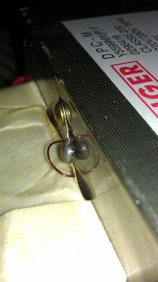
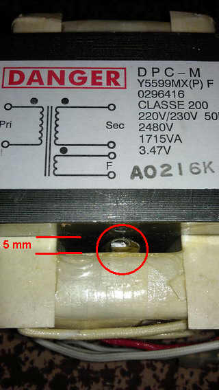
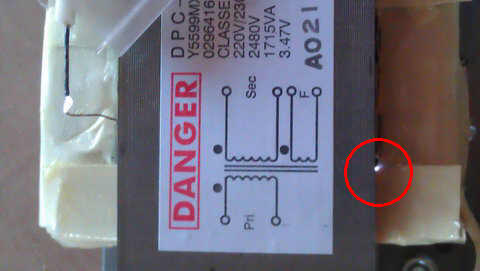
What about insulating the inner end of HV winding ? There is a ~2mm gap between the plastic bobbin and the core, where I could easily slide in a few sheets of these transparencies used for diy capacitors (or any other better insulating material, please suggest).
And if I get rid of the thermal protection, I might be able to slide the whole windings assembly towards the other side, thus having the inner secondary end 5mm away from the core (I could even put the thermal protection back on the other side)
Sounds good ?
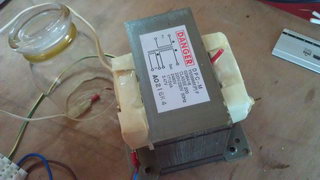
I don't know if the HV output wire of the MOT (the white one on above pic) is supposed to touch any grounded part in the oven, but it's insulation is rather thin.
Is it a good idea to remove the MOT's shunt ?
PhilGood, Mon Jul 23 2012, 03:33AM
Steve, loud bangs are part of the fun
 Thanks for the clarification, I was thinking the voltage doublers were partially smoothing output. I will add a few µF after them.
 Oh btw Steve, could you please move this thread to HV or TC section ? It no longer belongs to General Electronics.
Thanks Dr. DC, I fully understand what you meant about RF ground

Possible alternative :
What about insulating the inner end of HV winding ? There is a ~2mm gap between the plastic bobbin and the core, where I could easily slide in a few sheets of these transparencies used for diy capacitors (or any other better insulating material, please suggest).
And if I get rid of the thermal protection, I might be able to slide the whole windings assembly towards the other side, thus having the inner secondary end 5mm away from the core
 (I could even put the thermal protection back on the other side)
Sounds good ?
I don't know if the HV output wire of the MOT (the white one on above pic) is supposed to touch any grounded part in the oven, but it's insulation is rather thin.
Is it a good idea to remove the MOT's shunt ?
Re: MOT full wave rectification and grounding problems
Steve Conner, Mon Jul 23 2012, 10:03AM
Well, loud bangs are part of the fun for sure. But the most likely scenario is an arc inside the tube, between the plate and a grid. If the arc has enough energy, it can blow a hole in the grid rendering the tube useless.
Tube makers like Eimac and Svetlana recommend the use of a "glitch resistor" to limit arc current, and in extreme cases sacrifice itself to save the tube. It's something to think about if building a VTTC with a big smoothing capacitor bank.
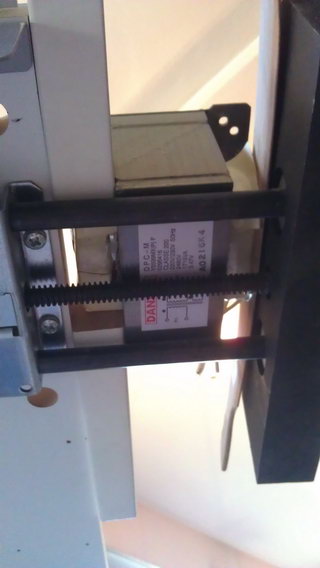
My ideas on multipliers are based on the good results I got with this one: It produced over 1kW at 10kV DC from a single MOT.
Steve Conner, Mon Jul 23 2012, 10:03AM
Well, loud bangs are part of the fun for sure. But the most likely scenario is an arc inside the tube, between the plate and a grid. If the arc has enough energy, it can blow a hole in the grid rendering the tube useless.
Tube makers like Eimac and Svetlana recommend the use of a "glitch resistor" to limit arc current, and in extreme cases sacrifice itself to save the tube.
 It's something to think about if building a VTTC with a big smoothing capacitor bank.
My ideas on multipliers are based on the good results I got with this one:
 It produced over 1kW at 10kV DC from a single MOT.
Re: MOT full wave rectification and grounding problems
Dr. Dark Current, Mon Jul 23 2012, 10:54AM
The insulation on the inner end of the secondary winding is probably pretty weak and might not take the 3kV peaks it would see, I don't recommend doing that, though many people do it.
Dr. Dark Current, Mon Jul 23 2012, 10:54AM
The insulation on the inner end of the secondary winding is probably pretty weak and might not take the 3kV peaks it would see, I don't recommend doing that, though many people do it.
Re: MOT full wave rectification and grounding problems
PhilGood, Tue Jul 24 2012, 09:17AM
 More seriously, this glitch resistor is a nice idea, I will add this to my circuit ! I also like your MOT powered VTTC with the voltage quadrupler
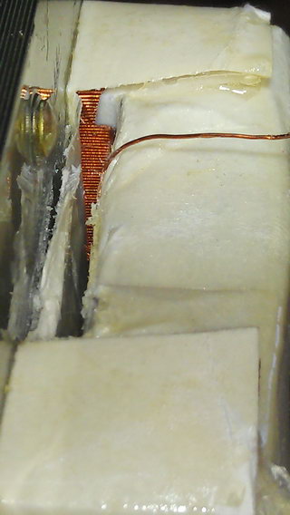
I took away the filament winding and the shunts, then I was able to slide the secondary in order to have the inner HV end 5mm away from the core.
Bad news here : I can see the secondary is wound on the core with little insulation, just two layers of what I think is varnish impregnated cardboard. (I was expecting some kind of plastic form a few mm thick).
But there's good news too : the secondary outer layer is very close to the core too and is not better insulated. Maybe this varnished cardboard has better dielectric properties than I thought.
As a test, after putting the shunts back in, I hooked my MOT to my variac, and I hooked the normal HV output (outer end) to the grounded MOT core through a 10R 1/4W resistor (glitch resistor ^^).
I slowly turned the variac up to 250V expecting a funny big bang, but nothing happened. Well ok the secondary was not under load, but still the inner secondary layer was at max output voltage...
Do you think I can consider this MOT reliable for intended use ? (full wave rectification for base fed HFVTTC).
I could even pour polyurethane varnish or Envirotex Lite epoxy into the heated secondary to improve its insulation a little bit, which one would be better ?
PhilGood, Tue Jul 24 2012, 09:17AM
Steve Conner wrote ...
Well, loud bangs are part of the fun for sure. But the most likely scenario is an arc inside the tube, between the plate and a grid...
Well if somthing wrong happens in the tube, no big bang, no fun Well, loud bangs are part of the fun for sure. But the most likely scenario is an arc inside the tube, between the plate and a grid...
 More seriously, this glitch resistor is a nice idea, I will add this to my circuit ! I also like your MOT powered VTTC with the voltage quadrupler
Dr. Dark Current wrote ...
The insulation on the inner end of the secondary winding is probably pretty weak and might not take the 3kV peaks it would see, I don't recommend doing that, though many people do it.
I couldn't resist, too curious...The insulation on the inner end of the secondary winding is probably pretty weak and might not take the 3kV peaks it would see, I don't recommend doing that, though many people do it.
I took away the filament winding and the shunts, then I was able to slide the secondary in order to have the inner HV end 5mm away from the core.
Bad news here
 : I can see the secondary is wound on the core with little insulation, just two layers of what I think is varnish impregnated cardboard. (I was expecting some kind of plastic form a few mm thick).
But there's good news too
 : the secondary outer layer is very close to the core too and is not better insulated. Maybe this varnished cardboard has better dielectric properties than I thought.
As a test, after putting the shunts back in, I hooked my MOT to my variac, and I hooked the normal HV output (outer end) to the grounded MOT core through a 10R 1/4W resistor (glitch resistor ^^).
I slowly turned the variac up to 250V expecting a funny big bang, but nothing happened. Well ok the secondary was not under load, but still the inner secondary layer was at max output voltage...
Do you think I can consider this MOT reliable for intended use ? (full wave rectification for base fed HFVTTC).
I could even pour polyurethane varnish or Envirotex Lite epoxy into the heated secondary to improve its insulation a little bit, which one would be better ?
Re: MOT full wave rectification and grounding problems
Dr. Dark Current, Tue Jul 24 2012, 09:56AM
I tested a MOT for such use with 4kV AC between secondary and core, with a NST. Then I would consider it safe. The insulation on the outer end of the secondary is better of course, usually there is a plastic sheet formed into "U" shape around the winding.
Dr. Dark Current, Tue Jul 24 2012, 09:56AM
I tested a MOT for such use with 4kV AC between secondary and core, with a NST. Then I would consider it safe. The insulation on the outer end of the secondary is better of course, usually there is a plastic sheet formed into "U" shape around the winding.
Print this page
