
Capacitor Discharge Microspot Welder / Cutter
radhoo, Thu Feb 09 2012, 05:30PMAs seen on Hack A Day:

Project Start, January 2012
I've just completed the first tests of a new challenging project, a pulsed discharge micro spot welder and cutter tool. It stores energy into a huge capacitor bank, and discharges it via two electrodes in the given target, regularly metal foils/sheets. The logic and the precise timing (of the order of micro-seconds) is controlled by an AtMEGA16-16PU microcontroller running at 16MHz. It can be used for spot welding and for plasma cutting.
The power switch is handled by 5 power mosfets, IRFP2907, set in parallel and driven by a darlington array IC with further transistor amplification. A single mosfet is rated for 75V 209Amps and an extremely low Rds.
The tool currently operates in two modes
1) Micro spot soldering
A predefined (uC+LCD+controls) high current pulse is delivered to the two electrodes, when the trigger button is pressed. Metal wires or sheets pressed between the electrodes will be soldered.
2) Cutting
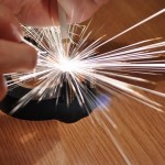
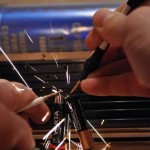
A burst of short pulses are sent to the electrodes to generate plasma and cut thin metal foils.
The pulse duration, repetition rates are configurable. I got best results with pairs of pulses. Duration in the range of tens - a few hundreds of microseconds. For welding, the first pulse melts the material, and the second consolidates the soldering. For cutting the first pulse does the damage, and the second pulse helps to clean the electrode off the molten micro spot.
More operating modes can be added, so please give me ideas!
TODOs:
- I need to find better electrodes, that do not stick to the material , I'm considering tungsten or graphite. Suggestions?
- bigger capacitor bank: I need more power, and will probably go for a 1Farad Car Audio capacitor . Those Sprague I'm currently using are not enough for ticker sheets.
- finish and publish the software
- publish schematics and PCB layout.
More details here:

update 2: February 9th, 2012
I need to decide what type of LCD to use: the 2 lines HD44780 LCD, or the bigger one, with 4 lines. The code I wrote works with both. The larger one would have the advantage of allowing more text to be displayed. The smaller one is on the other hand more compact, better suited for my small case.
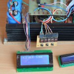
Update 3: February 22nd, 2012
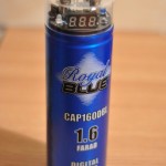
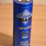
I purchased a suitable capacitor. Finally! It's a Pyramid Royal Blue, CAP160DBL 1.6V . The first thing I did was to dismantle the useless electronic part and the display. By doing so, the new size fits perfectly to my project box. For those complaining that this type of capacitor, when used for car audio systems, doesn't switch off and depletes the car battery, simply unscrew the connectors to take off the display part. You won't be needing that anyway:
Update 4: March 1st, 2012
The project box, in the final shape is ready. I had to cut some more wood, but that's an easy task if using the proper tools (I got a nice pendular saw). For a quick test I tried using a halogen 12V electronic transformer. That was a waste of time, as those things are unstable, and not working properly (they are barely oscillating):
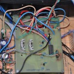
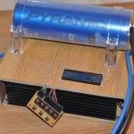
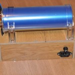
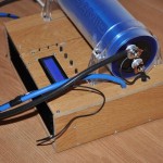
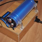
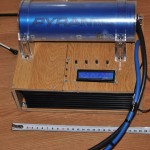
The box exposes the heatsink, a standard PC power connector, and a fuse holder. The big capacitor is mounted on the top, as it looks nice and is too big to fit inside anyway.
Update 5: March 3rd, 2012
I resisted the temptation to throw that halogen electronic transformer to the trash. It was such a waste of time! Instead I found a charger, from an old laptop. It is a 90W, 19.5V SMPS supply, with the perfect size for my box. Initial tests shown it is capable of charging the capacitor (with a short initial blackout), and even hold the intense Arc cutting mode power consumption. As this was another Chinese cheapo, some optional components such as filter, capacitors, etc where missing from the PCB, and I added those first. Next I did a heatsink upgrade, to make sure it will run continuously, for as long as I need to use the tool:
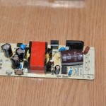
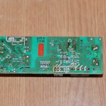
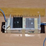
So far this proved to be an excellent choice! My device can now be powered from a 110V-220V outlet.
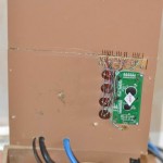
For the control panel, I needed a few potentiometers and some push buttons. I used a few NOS Russian 47K pots, I got from Gintaras Ebay show, KWTUBES. You can get some high quality components there at fair prices.
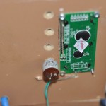
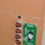
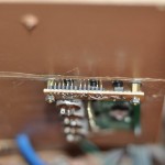
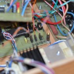
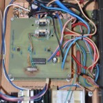
Some pins are used to interface with the floating cables coming from the PCB modules. By doing so, I can easily dismantle and re-mantle everything together.
Here's how the setup looks like now:
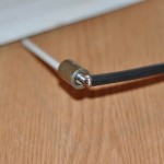
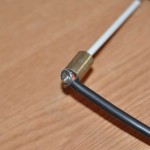
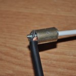
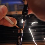
For the working electrodes I ended up using copper. But not just copper, also a new innovative design: the thick wires are connected to the electrodes using a screw, a screw nut and a washer. The electrode itself is a 10cm metal hollow tube. Inside, copper wire can be inserted, and while working, it can be pulled outside when needed. Exactly like a rotring pencil : the cooper electrodes is eaten while in use, but conveniently can be extracted from within the electrode, or replaced.
Finally, here's the completed project:
Construction details here:

Re: Capacitor Discharge Microspot Welder / Cutter
Inducktion, Thu Feb 09 2012, 07:18PM
Wouldn't a 1 farad audio cap have too much ESR? Why not try using some of those Maxwell Boostcapacitors? Their ESR is .7 milliohms, which is insanely low, considering it's a whopping 2600 farads of capacitance.
Inducktion, Thu Feb 09 2012, 07:18PM
Wouldn't a 1 farad audio cap have too much ESR? Why not try using some of those Maxwell Boostcapacitors? Their ESR is .7 milliohms, which is insanely low, considering it's a whopping 2600 farads of capacitance.
Re: Capacitor Discharge Microspot Welder / Cutter
m4ge123, Thu Feb 09 2012, 08:09PM
The series resistance of the boostcap (0.7mOhm), the MOSFET array (0.9mOhm), and random wires (up to 100mOhm) will really limit the current when working with low voltage. I would aim for at least 12 volts in the caps. If you're not going to use ultracaps, I don't see a reason to use anything less than 30V though.
Re: Capacitor Discharge Microspot Welder / Cutter
Patrick, Fri Feb 10 2012, 12:15AM
i was thinking of putting some ultraltra caps in series, 2600F / 10 = 260 F at 20 or so volts.
Could a NC machine use this device as its quill? then we could NC the copper foil off circuit boards! no more acid.
Patrick, Fri Feb 10 2012, 12:15AM
i was thinking of putting some ultraltra caps in series, 2600F / 10 = 260 F at 20 or so volts.
Could a NC machine use this device as its quill? then we could NC the copper foil off circuit boards! no more acid.
Re: Capacitor Discharge Microspot Welder / Cutter
Daedronus, Fri Feb 10 2012, 08:49AM
If you want to use a CNC to make pcb boards just use a V or pyramid engraving bit.
This is what I use and it works very well, I can get some very fine and thin isolation traces, around 12mils.
As a bonus you only have to change the bit to drill the holes and cut out the board.
Just don't go for the ultra thin V bits (20 or 30 degrees) you will break them. 60 degrees bits are fine.
Re: Capacitor Discharge Microspot Welder / Cutter
Turkey9, Fri Feb 10 2012, 09:21AM
Wow that's pretty sweet! I never would have thought to do this, good job.
Turkey9, Fri Feb 10 2012, 09:21AM
Wow that's pretty sweet! I never would have thought to do this, good job.
Re: Capacitor Discharge Microspot Welder / Cutter
Dalus, Fri Feb 10 2012, 09:30AM
You can get more info by going to this guys site
Dalus, Fri Feb 10 2012, 09:30AM
You can get more info by going to this guys site

Re: Capacitor Discharge Microspot Welder / Cutter
radhoo, Fri Feb 10 2012, 10:10AM
I cannot use 30V, the discharges would be too extreme / the arc too extended. I need this to work as "micro" as possible: nice , clean cuts, with the minimum level of sparks possible.
However I am aware that ESR and wire resistance creates considerable problems. I already plan to implement the following, in the capacitor-mosfet array-discharge electrodes: shorter and ticker wires, MKT quality caps in parallel with the electrolytic I am using, for a lower ESR combined factor and faster discharge response, try to go up to 20V and see how it performs.
Yes, but that design uses a PIC microcontroller. I'm more like an Atmel fan. Now that the hardware is done (more or less the capacitor bank part) I have total freedom to adjust the software. As a software developer, this will be fun and easy.
So guys, are there any suggestions on new and innovative operation modes?
Just think about the setup, we have this huge energy stored in a capacitor, and we can deliver it as precisely calculated pulses. What else to do with it?
Don't tell me to drive a flyback
LE reading about EDL caps, I found some interesting details:
Very low internal resistance allows extremely rapid discharge when shorted, resulting in a spark hazard similar to any other capacitor of similar voltage and capacitance (generally much higher than electrochemical cells).
Apparently the only limitation applying to my setup would be:
Low maximum voltage – series connections are needed to obtain higher voltages, and voltage balancing may be required. As Patrick already indicated.
radhoo, Fri Feb 10 2012, 10:10AM
Inducktion wrote ...
Wouldn't a 1 farad audio cap have too much ESR? Why not try using some of those Maxwell Boostcapacitors? Their ESR is .7 milliohms, which is insanely low, considering it's a whopping 2600 farads of capacitance.
I definitely need to bring an ESR-meter when going to the car audio shop looking for these caps.Wouldn't a 1 farad audio cap have too much ESR? Why not try using some of those Maxwell Boostcapacitors? Their ESR is .7 milliohms, which is insanely low, considering it's a whopping 2600 farads of capacitance.
m4ge123 wrote ...
The series resistance of the boostcap (0.7mOhm), the MOSFET array (0.9mOhm), and random wires (up to 100mOhm) will really limit the current when working with low voltage. I would aim for at least 12 volts in the caps. If you're not going to use ultracaps, I don't see a reason to use anything less than 30V though.
It 0.7mO is the only limitation of these boostcaps , it might be a good idea to get one for a few tests which I probably will.The series resistance of the boostcap (0.7mOhm), the MOSFET array (0.9mOhm), and random wires (up to 100mOhm) will really limit the current when working with low voltage. I would aim for at least 12 volts in the caps. If you're not going to use ultracaps, I don't see a reason to use anything less than 30V though.
I cannot use 30V, the discharges would be too extreme / the arc too extended. I need this to work as "micro" as possible: nice , clean cuts, with the minimum level of sparks possible.
However I am aware that ESR and wire resistance creates considerable problems. I already plan to implement the following, in the capacitor-mosfet array-discharge electrodes: shorter and ticker wires, MKT quality caps in parallel with the electrolytic I am using, for a lower ESR combined factor and faster discharge response, try to go up to 20V and see how it performs.
Patrick wrote ...
i was thinking of putting some ultraltra caps in series, 2600F / 10 = 260 F at 20 or so volts.
Could a NC machine use this device as its quill? then we could NC the copper foil off circuit boards! no more acid.
Yes, adding this device as a cutting head to a plotter/CNC is possible. i was thinking of putting some ultraltra caps in series, 2600F / 10 = 260 F at 20 or so volts.
Could a NC machine use this device as its quill? then we could NC the copper foil off circuit boards! no more acid.
Yes, but that design uses a PIC microcontroller. I'm more like an Atmel fan. Now that the hardware is done (more or less the capacitor bank part) I have total freedom to adjust the software. As a software developer, this will be fun and easy.
So guys, are there any suggestions on new and innovative operation modes?
Just think about the setup, we have this huge energy stored in a capacitor, and we can deliver it as precisely calculated pulses. What else to do with it?
Don't tell me to drive a flyback

LE reading about EDL caps, I found some interesting details:
Very low internal resistance allows extremely rapid discharge when shorted, resulting in a spark hazard similar to any other capacitor of similar voltage and capacitance (generally much higher than electrochemical cells).
Apparently the only limitation applying to my setup would be:
Low maximum voltage – series connections are needed to obtain higher voltages, and voltage balancing may be required. As Patrick already indicated.
Re: Capacitor Discharge Microspot Welder / Cutter
Proud Mary, Fri Feb 10 2012, 10:26AM
Pulse electrolysis. There are dozens and dozens of papers about it.
Proud Mary, Fri Feb 10 2012, 10:26AM
Pulse electrolysis. There are dozens and dozens of papers about it.
Re: Capacitor Discharge Microspot Welder / Cutter
Tonskulus, Fri Feb 10 2012, 02:21PM
I made similar metal sheet cutter using welder transformer, rectifier, cap bank and heavy choke and carbon electrode.
For thin metals, I use just scissors as it is much faster way :)
Nice project anyway!
Tonskulus, Fri Feb 10 2012, 02:21PM
I made similar metal sheet cutter using welder transformer, rectifier, cap bank and heavy choke and carbon electrode.
For thin metals, I use just scissors as it is much faster way :)
Nice project anyway!
Re: Capacitor Discharge Microspot Welder / Cutter
radhoo, Fri Feb 10 2012, 03:36PM
 . So will stick the electrodes into some electrolyte and see if the amount of gas can be increased in some way at constant temperature and pressure. Honestly, I don't expect pulse electrolysis to provide any noticeable results over CC electrolysys, nor the molecules to follow the magic pulsed/PWM signal like the rats the Pied Piper of Hamelin. I'm just saying this because I've seen lots of youtube users and hobbyists searching for the perpetuum mobile in terms of magic brown gas, HHO, or water cells. These comments do not target you, off course, since you are a very knowledgeable person in many technical fields.
BTW, I tested carbon electrodes and got some very poor results when compared to cooper. They seem to limit the discharge, and at the power levels I'm currently using there is no place for yet another limitation. What I'm saying is I need more power in this system, and lower resistances. So next time I'm working on it I'll make sure to use several litz wires in parallel in the power circuit.
Have a beer:
radhoo, Fri Feb 10 2012, 03:36PM
Proud Mary wrote ...
Pulse electrolysis. There are dozens and dozens of papers about it.
No time to read Pulse electrolysis. There are dozens and dozens of papers about it.
 . So will stick the electrodes into some electrolyte and see if the amount of gas can be increased in some way at constant temperature and pressure. Honestly, I don't expect pulse electrolysis to provide any noticeable results over CC electrolysys, nor the molecules to follow the magic pulsed/PWM signal like the rats the Pied Piper of Hamelin. I'm just saying this because I've seen lots of youtube users and hobbyists searching for the perpetuum mobile in terms of magic brown gas, HHO, or water cells. These comments do not target you, off course, since you are a very knowledgeable person in many technical fields.
Tonskulus wrote ...
I made similar metal sheet cutter using welder transformer, rectifier, cap bank and heavy choke and carbon electrode.
For thin metals, I use just scissors as it is much faster way :)
Nice project anyway!
Thanks. You can't do spot welding with the setup you're describing. You can , however, achieve it easily with this setup.I made similar metal sheet cutter using welder transformer, rectifier, cap bank and heavy choke and carbon electrode.
For thin metals, I use just scissors as it is much faster way :)
Nice project anyway!
BTW, I tested carbon electrodes and got some very poor results when compared to cooper. They seem to limit the discharge, and at the power levels I'm currently using there is no place for yet another limitation. What I'm saying is I need more power in this system, and lower resistances. So next time I'm working on it I'll make sure to use several litz wires in parallel in the power circuit.
Have a beer:
Re: Capacitor Discharge Microspot Welder / Cutter
Proud Mary, Fri Feb 10 2012, 04:05PM
I wasn't thinking of the new alchemy when I posted my suggestion - but more of established industrial processes like electroplating and electropolishing, where pulsed current is often used.
Proud Mary, Fri Feb 10 2012, 04:05PM
radhoo wrote ...
 . So will stick the electrodes into some electrolyte and see if the amount of gas can be increased in some way at constant temperature and pressure. Honestly, I don't expect pulse electrolysis to provide any noticeable results over CC electrolysys, nor the molecules to follow the magic pulsed/PWM signal like the rats the Pied Piper of Hamelin. I'm just saying this because I've seen lots of youtube users and hobbyists searching for the perpetuum mobile in terms of magic brown gas, HHO, or water cells. These comments do not target you, off course, since you are a very knowledgeable person in many technical fields.
Proud Mary wrote ...
Pulse electrolysis. There are dozens and dozens of papers about it.
No time to read Pulse electrolysis. There are dozens and dozens of papers about it.
 . So will stick the electrodes into some electrolyte and see if the amount of gas can be increased in some way at constant temperature and pressure. Honestly, I don't expect pulse electrolysis to provide any noticeable results over CC electrolysys, nor the molecules to follow the magic pulsed/PWM signal like the rats the Pied Piper of Hamelin. I'm just saying this because I've seen lots of youtube users and hobbyists searching for the perpetuum mobile in terms of magic brown gas, HHO, or water cells. These comments do not target you, off course, since you are a very knowledgeable person in many technical fields.
I wasn't thinking of the new alchemy
 when I posted my suggestion - but more of established industrial processes like electroplating and electropolishing, where pulsed current is often used.
Re: Capacitor Discharge Microspot Welder / Cutter
Inducktion, Fri Feb 10 2012, 07:17PM
What about tungsten plated copper?
I think the real reason why graphite and possibly tungsten limit the discharge so much is for the plain reason of just resistance...so if you use tungsten plated copper, you effectively get the conductivity of copper with the durability of tungsten.
I guess, think of how spark gaps are made!
Re: Capacitor Discharge Microspot Welder / Cutter
TwirlyWhirly555, Fri Feb 10 2012, 07:22PM
Great Build :) , Do you recon a 1F 25 Volt capaitor will be ok , i have one floating about i think it has pritty low ESR .
TwirlyWhirly555, Fri Feb 10 2012, 07:22PM
Great Build :) , Do you recon a 1F 25 Volt capaitor will be ok , i have one floating about i think it has pritty low ESR .
Re: Capacitor Discharge Microspot Welder / Cutter
radhoo, Fri Feb 10 2012, 08:28PM
radhoo, Fri Feb 10 2012, 08:28PM
Proud Mary wrote ...
more of established industrial processes like electroplating and electropolishing, where pulsed current is often used.
I don't know much about those, but I will try to experiment with this device as much as possible.more of established industrial processes like electroplating and electropolishing, where pulsed current is often used.
Inducktion wrote ...
I think the real reason why graphite and possibly tungsten limit the discharge so much is for the plain reason of just resistance...so if you use tungsten plated copper, you effectively get the conductivity of copper with the durability of tungsten.
A friend will be mailing me some neat tungsten blocks 3x5x30mm so we will find out. I think the real reason why graphite and possibly tungsten limit the discharge so much is for the plain reason of just resistance...so if you use tungsten plated copper, you effectively get the conductivity of copper with the durability of tungsten.
TwirlyWhirly555 wrote ...
Great Build :) , Do you recon a 1F 25 Volt capaitor will be ok , i have one floating about i think it has pritty low ESR .
Thanks, 1F 25V should be fine for this purpose. I am also considering Supercapacitors, but from what I understand car audio caps are the same.Great Build :) , Do you recon a 1F 25 Volt capaitor will be ok , i have one floating about i think it has pritty low ESR .
Re: Capacitor Discharge Microspot Welder / Cutter
Tonskulus, Mon Feb 13 2012, 09:56AM
I'm not sure if carbon electrode works at all with this kind of pulsed system.
Continuous arc is required I think.. this ensures that carbon never touches the actual material to be cutted. There is always gap / arc beetween them. Using smooth high current DC can produce very high temperature arc.
Re: Capacitor Discharge Microspot Welder / Cutter
radhoo, Tue Feb 14 2012, 03:29PM
Indeed carbon doesn't work. The discharges where so limited that they where unable to heat the material, not to mention cutting or soldering.
I'll be testing tungsten carbide during this week and post results.
radhoo, Tue Feb 14 2012, 03:29PM
Tonskulus wrote ...
I'm not sure if carbon electrode works at all with this kind of pulsed system.
Continuous arc is required I think.. this ensures that carbon never touches the actual material to be cutted. There is always gap / arc beetween them. Using smooth high current DC can produce very high temperature arc.
I'm not sure if carbon electrode works at all with this kind of pulsed system.
Continuous arc is required I think.. this ensures that carbon never touches the actual material to be cutted. There is always gap / arc beetween them. Using smooth high current DC can produce very high temperature arc.
Indeed carbon doesn't work. The discharges where so limited that they where unable to heat the material, not to mention cutting or soldering.
I'll be testing tungsten carbide during this week and post results.
Re: Capacitor Discharge Microspot Welder / Cutter
radhoo, Sun Mar 04 2012, 10:50PM
The project is ready!
update 2: February 9th, 2012
I need to decide what type of LCD to use: the 2 lines HD44780 LCD, or the bigger one, with 4 lines. The code I wrote works with both. The larger one would have the advantage of allowing more text to be displayed. The smaller one is on the other hand more compact, better suited for my small case.

Update 3: February 22nd, 2012
I purchased a suitable capacitor. Finally! It's a Pyramid Royal Blue, CAP160DBL 1.6V . The first thing I did was to dismantle the useless electronic part and the display. By doing so, the new size fits perfectly to my project box. For those complaining that this type of capacitor, when used for car audio systems, doesn't switch off and depletes the car battery, simply unscrew the connectors to take off the display part. You won't be needing that anyway:


Update 4: March 1st, 2012
The project box, in the final shape is ready. I had to cut some more wood, but that's an easy task if using the proper tools (I got a nice pendular saw). For a quick test I tried using a halogen 12V electronic transformer. That was a waste of time, as those things are unstable, and not working properly (they are barely oscillating):


The box exposes the heatsink, a standard PC power connector, and a fuse holder. The big capacitor is mounted on the top, as it looks nice and is too big to fit inside anyway.
Update 5: March 3rd, 2012
I resisted the temptation to throw that halogen electronic transformer to the trash. It was such a waste of time! Instead I found a charger, from an old laptop. It is a 90W, 19.5V SMPS supply, with the perfect size for my box. Initial tests shown it is capable of charging the capacitor (with a short initial blackout), and even hold the intense Arc cutting mode power consumption. As this was another Chinese cheapo, some optional components such as filter, capacitors, etc where missing from the PCB, and I added those first. Next I did a heatsink upgrade, to make sure it will run continuously, for as long as I need to use the tool:


So far this proved to be an excellent choice! My device can now be powered from a 110V-220V outlet.
For the control panel, I needed a few potentiometers and some push buttons. I used a few NOS Russian 47K pots, I got from Gintaras Ebay show, KWTUBES. You can get some high quality components there at fair prices.


Some pins are used to interface with the floating cables coming from the PCB modules. By doing so, I can easily dismantle and re-mantle everything together.
Here's how the setup looks like now:


For the working electrodes I ended up using copper. But not just copper, also a new innovative design: the thick wires are connected to the electrodes using a screw, a screw nut and a washer. The electrode itself is a 10cm metal hollow tube. Inside, copper wire can be inserted, and while working, it can be pulled outside when needed. Exactly like a rotring pencil : the cooper electrodes is eaten while in use, but conveniently can be extracted from within the electrode, or replaced.


Finally, here's the completed project:


Construction details here:
radhoo, Sun Mar 04 2012, 10:50PM
The project is ready!
update 2: February 9th, 2012
I need to decide what type of LCD to use: the 2 lines HD44780 LCD, or the bigger one, with 4 lines. The code I wrote works with both. The larger one would have the advantage of allowing more text to be displayed. The smaller one is on the other hand more compact, better suited for my small case.

Update 3: February 22nd, 2012
I purchased a suitable capacitor. Finally! It's a Pyramid Royal Blue, CAP160DBL 1.6V . The first thing I did was to dismantle the useless electronic part and the display. By doing so, the new size fits perfectly to my project box. For those complaining that this type of capacitor, when used for car audio systems, doesn't switch off and depletes the car battery, simply unscrew the connectors to take off the display part. You won't be needing that anyway:


Update 4: March 1st, 2012
The project box, in the final shape is ready. I had to cut some more wood, but that's an easy task if using the proper tools (I got a nice pendular saw). For a quick test I tried using a halogen 12V electronic transformer. That was a waste of time, as those things are unstable, and not working properly (they are barely oscillating):


The box exposes the heatsink, a standard PC power connector, and a fuse holder. The big capacitor is mounted on the top, as it looks nice and is too big to fit inside anyway.
Update 5: March 3rd, 2012
I resisted the temptation to throw that halogen electronic transformer to the trash. It was such a waste of time! Instead I found a charger, from an old laptop. It is a 90W, 19.5V SMPS supply, with the perfect size for my box. Initial tests shown it is capable of charging the capacitor (with a short initial blackout), and even hold the intense Arc cutting mode power consumption. As this was another Chinese cheapo, some optional components such as filter, capacitors, etc where missing from the PCB, and I added those first. Next I did a heatsink upgrade, to make sure it will run continuously, for as long as I need to use the tool:


So far this proved to be an excellent choice! My device can now be powered from a 110V-220V outlet.
For the control panel, I needed a few potentiometers and some push buttons. I used a few NOS Russian 47K pots, I got from Gintaras Ebay show, KWTUBES. You can get some high quality components there at fair prices.


Some pins are used to interface with the floating cables coming from the PCB modules. By doing so, I can easily dismantle and re-mantle everything together.
Here's how the setup looks like now:


For the working electrodes I ended up using copper. But not just copper, also a new innovative design: the thick wires are connected to the electrodes using a screw, a screw nut and a washer. The electrode itself is a 10cm metal hollow tube. Inside, copper wire can be inserted, and while working, it can be pulled outside when needed. Exactly like a rotring pencil : the cooper electrodes is eaten while in use, but conveniently can be extracted from within the electrode, or replaced.


Finally, here's the completed project:


Construction details here:

Re: Capacitor Discharge Microspot Welder / Cutter
radhoo, Sun Mar 11 2012, 10:41AM
Project featured on Hack A Day:

radhoo, Sun Mar 11 2012, 10:41AM
Project featured on Hack A Day:


Re: Capacitor Discharge Microspot Welder / Cutter
radhoo, Sun Mar 18 2012, 01:21PM
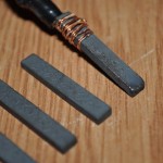
I recently received a few Tungsten Carbide rods. This excellent material has a high melting point (2,870 °C), it is extremely hard (8.5–9.0 Mohs scale) with low electrical resistivity (~2×10⁻⁷ Ohm·m) making it an good electrode material for the Capacitor Welder. I hope to see it solves the molten sticky metal issue I had with copper electrodes.
Results show excellent performance:
Here are the electrodes showing minor signs of use after this cutting session:

Re: Capacitor Discharge Microspot Welder / Cutter
Thomas W, Sun Mar 18 2012, 03:28PM
that is awsome, i wish i had the know how to make somthing like that, ah well, mabye i will oneday ^^
Thomas W, Sun Mar 18 2012, 03:28PM
that is awsome, i wish i had the know how to make somthing like that, ah well, mabye i will oneday ^^
Re: Capacitor Discharge Microspot Welder / Cutter
radhoo, Sun Mar 18 2012, 11:14PM
radhoo, Sun Mar 18 2012, 11:14PM
Tom Williamson wrote ...
that is awsome, i wish i had the know how to make somthing like that, ah well, mabye i will oneday ^^
Thank you, let me know if I can help. The project itself is easy, just a uC controlled mosfet array for discharging the capacitor in pulses.that is awsome, i wish i had the know how to make somthing like that, ah well, mabye i will oneday ^^
Print this page