Class E Coil Woes
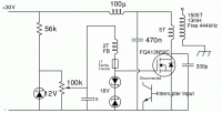
The Lightning Stalker, Thu Dec 22 2011, 11:10PMI'm trying to get a simple Armstrong oscillator going and keep blowing MOSFETS. It just doesn't make any sense. There are 18V Zener diodes on the gate and the power supply is limited to 5A. At $6 apiece I can't afford to buy that many at a time and have to wait over a week for them to arrive. I can't get SPICE simulations to oscillate. It's based on WaveRider's design. That man is a genius.
This schematic is old. Scroll down for an update:
Re: Class E Coil Woes
Dr. Dark Current, Thu Dec 22 2011, 11:50PM
This post has been removed, I just realised the coil in question is class E not C...
Anyway, the drain cap is way too small.
Dr. Dark Current, Thu Dec 22 2011, 11:50PM
This post has been removed, I just realised the coil in question is class E not C...
Anyway, the drain cap is way too small.
Re: Class E Coil Woes
The Lightning Stalker, Fri Dec 23 2011, 02:03AM
Thank you for the reply. How do I determine what size drain cap to start out with? The class E calculators say to use around 1300pF at this frequency. The output capacitance of the MOSFET alone is already 1250p. Also the component arrangement is a little different than the Sokal circuit leading to some confusion on my part.
Re: Class E Coil Woes
teravolt, Fri Dec 23 2011, 04:10AM
Do you have a transformer or variac to test it at lower voltages? another thing you could add some resistance in series with the 100uH inductor say 5 ohms till you can find out whats going on. Once you get it resonant there will be alot of voltage developed over your 100pf cap and accross your fet. Is you FB turn phased right?
Re: Class E Coil Woes
The Lightning Stalker, Fri Dec 23 2011, 04:38AM
I was running it on an isolated variac with a 300W light bulb in series to limit the current and trying the FB winding in both directions since I'm not sure which way is right. So far I haven't had the chance to hook up the interrupter.
The Lightning Stalker, Fri Dec 23 2011, 04:38AM
I was running it on an isolated variac with a 300W light bulb in series to limit the current and trying the FB winding in both directions since I'm not sure which way is right. So far I haven't had the chance to hook up the interrupter.
Re: Class E Coil Woes
Dr. Dark Current, Fri Dec 23 2011, 05:23PM
The interrupter transistor is missing a diode in its collector. Without the diode, the base-emitter junction will break down during the operation, and the base drive signal will get huge rf ripple.
Dr. Dark Current, Fri Dec 23 2011, 05:23PM
The interrupter transistor is missing a diode in its collector. Without the diode, the base-emitter junction will break down during the operation, and the base drive signal will get huge rf ripple.
Re: Class E Coil Woes
Marko, Fri Dec 23 2011, 10:53PM
Such circuits with mosfets are extremely fiddly to bias. You might get it biased right at low voltage, only for it to become unhappy on higher voltages, or have it self destruct after the gate threshold voltage drops too much due to elevated temperature and the mosfet latches permanently on.
You'r likely need to adjust your feedback winding in steps as you progress with voltage increments. A variable loading cap would probably be a good idea too.
marko
Marko
Marko, Fri Dec 23 2011, 10:53PM
The Lightning Stalker wrote ...
I'm trying to get a simple Armstrong oscillator going and keep blowing MOSFETS. It just doesn't make any sense. There are 18V Zener diodes on the gate and the power supply is limited to 5A. At $6 apiece I can't afford to buy that many at a time and have to wait over a week for them to arrive. I can't get SPICE simulations to oscillate. It's based on WaveRider's design. That man is a genius.
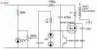
Circuit as it is now:

Such circuits with mosfets are extremely fiddly to bias. You might get it biased right at low voltage, only for it to become unhappy on higher voltages, or have it self destruct after the gate threshold voltage drops too much due to elevated temperature and the mosfet latches permanently on.
You'r likely need to adjust your feedback winding in steps as you progress with voltage increments. A variable loading cap would probably be a good idea too.
marko
Marko
Re: Class E Coil Woes
The Lightning Stalker, Sun Dec 25 2011, 01:22AM
Deleted double post
The Lightning Stalker, Sun Dec 25 2011, 01:22AM
Deleted double post
Re: Class E Coil Woes
The Lightning Stalker, Sun Dec 25 2011, 01:35AM
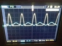
I couldn't find a decent diode, so I just took the interrupter transistor out of the circuit. After a lot of fiddling it finally has a nice arc at 30V. The transistor is just getting a little warm and the waveform is beautiful. The secondary actually gets hotter than the transistor does and it's on a smallish heat sink (out of a small ATX power supply but it's thick, like 8mm). The transistor is temporarily a Fairchild FQA13N50C out of an old ATX PSU since I ran out of the "good" Infineons.
I ended up putting a ferrite in series with the feedback winding to take care of some higher frequency ringing which got really bad as I increased voltage. It also delayed the turn on time so it wasn't turning on too soon.
It's running at about 3MHz which is way above the target of 444KHz, so more tweaking needs to be done. It's not quite running at true Class E yet, but it's pretty close.
I'll post some pictures when my mom gets done watching TV since it's interfering with it. I'll also update the schematic.
Re: Class E Coil Woes
The Lightning Stalker, Sun Dec 25 2011, 09:29PM
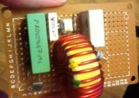
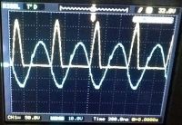
Here are the trace shots as well as a picture of the board before I soldered everything in just to make sure I'm doing everything right. The first one is with the ferrite and the second is without. Sorry I forgot to take a streamer pic. It's not all that impressive anyway.
Strangely enough, it won't produce a streamer without the ferrite. The streamer won't start by itself either. I have to get it going with a screwdriver. I'm actually surprised there is one at all considering how far above the resonance frequency it's running. Also the ferrite is getting pretty warm. I probably should find one made from a better material.
See anything I'm doing wrong?
Thank you for all your advice, BTW!


Re: Class E Coil Woes
The Lightning Stalker, Mon Jan 02 2012, 08:47PM
I have an update and question on this project, which I am calling the leaning coil of Tesla. ^_-
All I can get is a small streamer. As I turn up the voltage on the variac, the streamer grows as expected, and the fluorescent tube next to it gets brighter. Then as I keep turning up the voltage past a certain point it starts to decrease until around 50V it goes out. Does anyone have an idea of what could be causing this?
Thank you.
Edit: I should also say that the scope shows no change in the gate/drain waveforms aside from the increasing voltage, Just no output from the secondary.
Re: Class E Coil Woes
Marko, Mon Jan 02 2012, 10:31PM
Well, as I said it's a fiddly circuit and you may need to re-adjust the feedback coil coupling and the bias voltage as supply voltage is increased. While doing so, blowing mosfets is highly probable...
It would probably be helpful to have some way of measuring tab temperature, or just watching the voltage and current waveforms closely ona fast oscilloscope.
Marko
Re: Class E Coil Woes
Myke, Tue Jan 03 2012, 08:29AM
Just wondering, shouldn't the load be connected across the switching device (in this case, a MOSFET)? The class E amplifiers I've seen all do this since they need a constant current supply across the switching device and shunt capacitance. Having the load connected in series means that you have less control of the voltage across the MOSFET. Normally, it should follow the integral of the current through the shunt capacitance.
You should also be careful of self resonant topologies because if you lose gate drive and the MOSFET gets stuck on, it'll probably die.
Re: Class E Coil Woes
The Lightning Stalker, Tue Jan 03 2012, 08:20PM
It is switching just fine at higher voltages, just no secondary output. I'm starting to think maybe I should just abandon this secondary and wind a new one.
The Lightning Stalker, Tue Jan 03 2012, 08:20PM
It is switching just fine at higher voltages, just no secondary output. I'm starting to think maybe I should just abandon this secondary and wind a new one.
Re: Class E Coil Woes
Inducktion, Wed Jan 04 2012, 04:57PM
If it's at 444 khz, then you probably don't even need class E.
A regular half bridge of mosfets would handle this coil just fine.
Inducktion, Wed Jan 04 2012, 04:57PM
If it's at 444 khz, then you probably don't even need class E.
A regular half bridge of mosfets would handle this coil just fine.
Re: Class E Coil Woes
teravolt, Wed Jan 04 2012, 06:12PM
Have you tried making your primary smaller and increasing coupling?
teravolt, Wed Jan 04 2012, 06:12PM
Have you tried making your primary smaller and increasing coupling?
Print this page
