DR tank impedance, lower vs. upper pole
Dr. Dark Current, Sun Nov 27 2011, 05:10PMHello,
while experimenting with my non-interrupted DRSSTC running on the lower pole, I noticed that with increasing bridge voltage from zero, the tank current quickly rises but then it kind of "flattens out" and there is not much more increase of output current with higher bridge voltage - the tank impedance increases.
I guess this might have something to do with the spark loading decreasing the secondary resonant frequency and pulling the coil more in tune, decreasing primary Q.
Now my question is - what is the expected behavior on the upper pole?
Applying my spark loading theory, the tank current should be low until a certain voltage, at which the sparks become big enough to detune the secondary coil further away from the primary tank frequency, increasing its Q and current.
Does this sound about right or am I completely off?
Re: DR tank impedance, lower vs. upper pole
Steve Conner, Sun Nov 27 2011, 05:45PM
As far as I know, the two poles behave the same with respect to resistive damping.
But detuning by streamer capacitance affects the two poles oppositely. It increases the tank impedance if you're running on the lower pole, and decreases it if you're running on the upper one.
Or maybe I've got that backwards The graphs recently posted by Uspring show the effect. Basically the effective transformation ratio changes according to the difference between the primary and secondary resonant frequencies, which is why you can "tune" a DRSSTC by adjusting the primary tap.
I'm not sure which one is better. You can argue that a system running on the lower pole is adjusting itself to better match the spark as it gets bigger, hotter and lower impedance.
Steve Conner, Sun Nov 27 2011, 05:45PM
As far as I know, the two poles behave the same with respect to resistive damping.
But detuning by streamer capacitance affects the two poles oppositely. It increases the tank impedance if you're running on the lower pole, and decreases it if you're running on the upper one.
Or maybe I've got that backwards
 The graphs recently posted by Uspring show the effect. Basically the effective transformation ratio changes according to the difference between the primary and secondary resonant frequencies, which is why you can "tune" a DRSSTC by adjusting the primary tap.
I'm not sure which one is better. You can argue that a system running on the lower pole is adjusting itself to better match the spark as it gets bigger, hotter and lower impedance.
Re: DR tank impedance, lower vs. upper pole
Dr. Dark Current, Sun Nov 27 2011, 06:08PM
Steve, do you think the dynamic tank circuit impedance has an effect on the spark appearance? Assuming the same driving frequency, which pole should be better to get sparks as straight as possible (either by using the ramp up from mains waveform, or QCW modulated supply)?
Re: DR tank impedance, lower vs. upper pole
Steve Conner, Sun Nov 27 2011, 06:15PM
I don't know! And I wouldn't be surprised if my QCW approach, with the current control loop, preferred the opposite pole to Steve Ward's approach, controlling DC bus voltage.
However, the upper pole is still preferred because it lets you achieve a higher operating frequency, and hence straighter sparks, with whatever resonator you had handy. This is why Steve and Eric use it.
The upper pole also allows tighter coupling without flashovers, because it has a concave voltage profile: the voltage gradient is lowest at the bottom of the resonator and increases towards the topload. The lower pole has a convex one, making flashovers worse. I worked this out from theory, and Richie B. confirmed it by experiments with a voltage probe.
Steve Conner, Sun Nov 27 2011, 06:15PM
I don't know!
 And I wouldn't be surprised if my QCW approach, with the current control loop, preferred the opposite pole to Steve Ward's approach, controlling DC bus voltage.
However, the upper pole is still preferred because it lets you achieve a higher operating frequency, and hence straighter sparks, with whatever resonator you had handy.
 This is why Steve and Eric use it.
The upper pole also allows tighter coupling without flashovers, because it has a concave voltage profile: the voltage gradient is lowest at the bottom of the resonator and increases towards the topload. The lower pole has a convex one, making flashovers worse. I worked this out from theory, and Richie B. confirmed it by experiments with a voltage probe.
Re: DR tank impedance, lower vs. upper pole
Dr. Dark Current, Sun Nov 27 2011, 06:39PM
Interesting It would seem that running the lower pole, you can wind the resonator with a thicker wire and push more power into it.
Dr. Dark Current, Sun Nov 27 2011, 06:39PM
Interesting
 It would seem that running the lower pole, you can wind the resonator with a thicker wire and push more power into it.
Re: DR tank impedance, lower vs. upper pole
Goodchild, Sun Nov 27 2011, 07:49PM
Theoretically the lower pole also has the most gain. I have also used the natural resonant freq on my QCW with similar performance to the upper pole.
I plan to wind a higher freq secondary though and try tuning to the lower pole and see how this effects performance. I have a feeling that the capacitive loading of QCW sparks could be a lot higher that a regular DR making lower pole tuning a lot more practical.
Re: DR tank impedance, lower vs. upper pole
Dr. Dark Current, Sun Nov 27 2011, 07:57PM
Be sure to post the results
Dr. Dark Current, Sun Nov 27 2011, 07:57PM
Be sure to post the results

Re: DR tank impedance, lower vs. upper pole
Uspring, Mon Nov 28 2011, 12:22PM
Steve McConner wrote:
You got that right. I expect the primary current to rise as a consequence of detuning if running at the upper pole.
Steve also wrote:
You got me thinking on that one. This makes perfect sense to me. At the upper pole the magnetic fields of primary and secondary are in opposite phase so they cancel each other to a certain extent in the region where they overlap i.e. at the bottom of the secondary. Effectively that shortens the secondary coil, so that it has less inductance which makes its (coupled) frequency go up. That is the reason, why the upper pole is above the secondaries uncoupled frequency.
The phase difference between primary and secondary depends on the secondary loading, though. Under heavy loads it will go to 90 degrees, so that the cancellation is reduced.
Uspring, Mon Nov 28 2011, 12:22PM
Steve McConner wrote:
But detuning by streamer capacitance affects the two poles oppositely. It increases the tank impedance if you're running on the lower pole, and decreases it if you're running on the upper one.
Or maybe I've got that backwards. The graphs recently posted by Uspring show the effect. Basically the effective transformation ratio changes according to the difference between the primary and secondary resonant frequencies, which is why you can "tune" a DRSSTC by adjusting the primary tap.
You got that right. I expect the primary current to rise as a consequence of detuning if running at the upper pole.
Steve also wrote:
The upper pole also allows tighter coupling without flashovers, because it has a concave voltage profile: the voltage gradient is lowest at the bottom of the resonator and increases towards the topload. The lower pole has a convex one, making flashovers worse. I worked this out from theory, and Richie B. confirmed it by experiments with a voltage probe.
You got me thinking on that one. This makes perfect sense to me. At the upper pole the magnetic fields of primary and secondary are in opposite phase so they cancel each other to a certain extent in the region where they overlap i.e. at the bottom of the secondary. Effectively that shortens the secondary coil, so that it has less inductance which makes its (coupled) frequency go up. That is the reason, why the upper pole is above the secondaries uncoupled frequency.
The phase difference between primary and secondary depends on the secondary loading, though. Under heavy loads it will go to 90 degrees, so that the cancellation is reduced.
Re: DR tank impedance, lower vs. upper pole
Steve Conner, Mon Nov 28 2011, 01:14PM
Yes, I agree. As you showed in that earlier post, I believe that under heavy loading, the coil ends up in the same operating point, no matter which pole it started from.
The question is, do our coils ever get to this "heavy loading" condition? Could we find out by measuring the primary/secondary phase shift on the fly with a DSO?
An observation that might be relevant: Years ago, when a DRSSTC was still called an "ISSTC", everyone used secondary base current feedback. I showed that it couldn't give reliable zero current switching, because the primary-secondary phase shift varied a lot as a function of spark loading, and I tried to persuade everyone to shift to primary current feedback.
So maybe this proves that we do have "heavy loading".
Re: DR tank impedance, lower vs. upper pole
Dr. Dark Current, Mon Nov 28 2011, 10:28PM
But this is true only when the resonant frequencies of the two individual circuits are the same, right? When we tune for the upper or lower pole, we usually do this by actually detuning the primary tank to one or the other side, so the conclusions might not be true.
Dr. Dark Current, Mon Nov 28 2011, 10:28PM
Steve McConner wrote ...
Yes, I agree. As you showed in that earlier post, I believe that under heavy loading, the coil ends up in the same operating point, no matter which pole it started from.
Yes, I agree. As you showed in that earlier post, I believe that under heavy loading, the coil ends up in the same operating point, no matter which pole it started from.
But this is true only when the resonant frequencies of the two individual circuits are the same, right? When we tune for the upper or lower pole, we usually do this by actually detuning the primary tank to one or the other side, so the conclusions might not be true.
Re: DR tank impedance, lower vs. upper pole
Steve Conner, Tue Nov 29 2011, 07:38AM
Well, Uspring showed that if the secondary is loaded heavily enough, the two poles disappear, and there is only one frequency where zero current switching can be achieved.
My PLL drivers have always allowed to choose the operating pole independent of the tuning. With this in mind, I'm saying that the choice only matters for ignition and the early stages of the burst, and by the end of a long burst it will have converged to this single operating point.
With a feedback driver, you choose the operating pole by tuning, and tuning will also change the frequency and impedance of that loaded operating point.
Re: DR tank impedance, lower vs. upper pole
Goodchild, Tue Nov 29 2011, 08:15AM
This brings up something interesting that I noticed when playing with my QCW. On one run I swapped in a 10nF tank cap but I didn't have enough primary turns to bring the freq down to the secondary frequency. As a result the primary was running 20Khz higher that it should have been, yet the performance of the system was not hindered all that much.
What it did do however was change the performance during different parts of the burst. At higher power (top of ramp) the systems seemed unstable but at the beginning of the burst the system was very stable. This instability in the tuning resulted in a limited power level for a given tuning point before the the system became unstable and the sparks started to branch. This instability was even enough to mess with the regulation of the class D feeding the bridge.
Some one needs to come up with a way to make all this electronics stuff less complex, my brain hurts...
Eric
Goodchild, Tue Nov 29 2011, 08:15AM
This brings up something interesting that I noticed when playing with my QCW. On one run I swapped in a 10nF tank cap but I didn't have enough primary turns to bring the freq down to the secondary frequency. As a result the primary was running 20Khz higher that it should have been, yet the performance of the system was not hindered all that much.
What it did do however was change the performance during different parts of the burst. At higher power (top of ramp) the systems seemed unstable but at the beginning of the burst the system was very stable. This instability in the tuning resulted in a limited power level for a given tuning point before the the system became unstable and the sparks started to branch. This instability was even enough to mess with the regulation of the class D feeding the bridge.
Some one needs to come up with a way to make all this electronics stuff less complex, my brain hurts...

Eric
Re: DR tank impedance, lower vs. upper pole
Steve Conner, Tue Nov 29 2011, 08:41AM
It's not the electronics that's complex, it's the plasma physics! If the load were a big resistor we could design it easily.
Steve Conner, Tue Nov 29 2011, 08:41AM
It's not the electronics that's complex, it's the plasma physics! If the load were a big resistor we could design it easily.

Re: DR tank impedance, lower vs. upper pole
Uspring, Tue Nov 29 2011, 12:47PM
Steve wrote:
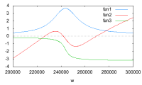
Yes, I think measuring the phase difference between primary and secondary current would be interesting. Below I've plotted as in my previous post on DRSSTC theory the real and imaginary part (blue and red) of the primary resistance as a function of frequency. In addition the green line shows the phase between the primary and secondary currents in radians.

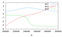
I've chosen a k of 0.2 and a secondary Q of 10 and uncoupled primary and secondary frequencies to be equal. The phase shift between the currents is near zero at the lower pole and near 180 degrees near the upper one. For the next diagram I've increased secondary loading, so that the Q is about 4.

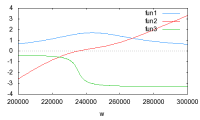
The poles are gone now. The existence of poles depends on the values of Q and k. If k*Q<1 you don't have poles. In my last diagram I've lowered the primary frequency a little bit so that the operating frequency (= zero crossing of red curve) is approximately at the position of a 90 degrees phase shift.

The point I want to make is, that if you have poles as in the first diagram, they will prevent you from getting a 90 degrees phase shift, because the poles are far above or below the 90 degrees point. If you don't have poles, you can tune your primary right to that place. So getting a 90 degrees shift is an indicator, that the poles have gone.
Dr. Kilovolt wrote:

You are also left with one operating frequency here, although k*Q>1. This rule applies only for the case, where primary and secondary are tuned to the same frequency.
Uspring, Tue Nov 29 2011, 12:47PM
Steve wrote:
The question is, do our coils ever get to this "heavy loading" condition? Could we find out by measuring the primary/secondary phase shift on the fly with a DSO?
Yes, I think measuring the phase difference between primary and secondary current would be interesting. Below I've plotted as in my previous post on DRSSTC theory the real and imaginary part (blue and red) of the primary resistance as a function of frequency. In addition the green line shows the phase between the primary and secondary currents in radians.

I've chosen a k of 0.2 and a secondary Q of 10 and uncoupled primary and secondary frequencies to be equal. The phase shift between the currents is near zero at the lower pole and near 180 degrees near the upper one. For the next diagram I've increased secondary loading, so that the Q is about 4.

The poles are gone now. The existence of poles depends on the values of Q and k. If k*Q<1 you don't have poles. In my last diagram I've lowered the primary frequency a little bit so that the operating frequency (= zero crossing of red curve) is approximately at the position of a 90 degrees phase shift.

The point I want to make is, that if you have poles as in the first diagram, they will prevent you from getting a 90 degrees phase shift, because the poles are far above or below the 90 degrees point. If you don't have poles, you can tune your primary right to that place. So getting a 90 degrees shift is an indicator, that the poles have gone.
Dr. Kilovolt wrote:
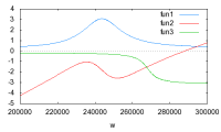
But this is true only when the resonant frequencies of the two individual circuits are the same, right? When we tune for the upper or lower pole, we usually do this by actually detuning the primary tank to one or the other side, so the conclusions might not be true.Ok, here is still another diagram. I've used the parameters of my first diagram but have detuned the primary up away from the secondary frequency.

You are also left with one operating frequency here, although k*Q>1. This rule applies only for the case, where primary and secondary are tuned to the same frequency.
Print this page