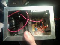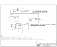
Regulated Fly-back Cap Bank Charger (555 timer)
Inducktion, Thu Oct 27 2011, 02:47AMI've recently designed a regulated cap bank charger circuit, which runs off of a 555 timer and two comparators. I'll post some videos tomorrow when I get back from school. It works perfectly!


Re: Regulated Fly-back Cap Bank Charger (555 timer)
Marko, Sat Oct 29 2011, 01:00AM
Hi inducktion
Have you considered using a royer oscillator to drive your transformer instead? You can enable and disable it quite easily by the same comparators, by controlling it's gate drive.
I once tried rigging up a simple "mazzili" circuit with IRFZ44's onto a ATX transformer hooked in reverse, and it seemed to give like few hundred watts without problems. I even pushed the transformer to some 600V out (although that caused it to heat a bit) and drove fluorescent tubes with it.
I don't know why anyone still uses the "NE555 boost converter" thing. It saturates the transformer heavily when driving a capacitive load, no good at all for this application.
Marko
Re: Regulated Fly-back Cap Bank Charger (555 timer)
klugesmith, Tue Nov 01 2011, 06:22AM
Nice work.
A couple of constructive criticisms:
1. The transformer in your schematic should have dots to indicate the relative polarity of the two windings. The circuit won't work if one winding is reversed.
2. Reference designators such as R1, R2, etc. are a good idea for several reasons. They allow a physical layout diagram to be invariant when you substitute a different R value or transistor type. They allow notes like "limit voltage is determined by R3" instead of "limit voltage is determined by the 1000 ohm resistor" -- what if there is more than one component of the same value as the one you are referring to?
Caution: if the cap bank is discharged into an underdamped inductive load, while this charger is still connected, your output diode is likely to blow when the capacitor
voltage becomes negative and the diode begins to carry the coil current.
Print this page
