Class E SSTC thread
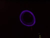
Marko, Tue Jul 04 2006, 10:40PMI've just done some 'higher power' tests on my small class E coil. It's running at 24V and 30-40 watts, have to measure this yet. I can get 6,5cm strikes (almost 3 inches) from this, tank voltage gets up to about 100V peak for now.
Interesting thing is that arc, after connecting, immediately wanders away, and coil continues to break out from topload on it's own for a while (completely in CW). It even pwned my old mini SGTC. Coil won't break out from topload if nothing is near, but I guess I need just a littel more voltage for that.
I like this shot, and there is also a video of this I can upload if anyone is interested.
This isn't a good stunt for a very flammable celluloid ball topload so I kept runs limited.

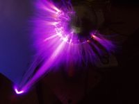
Now i'm willing to put it back into it's old wooden case.
I want it to be portable and power it from an external 12..15V source, and I don't mind dragging big mains transformers around or within the coil.
I always wanted to have a power supply inside the coil, wich would be on a relatively small board (not more than about 4*8cm) and provide voltages required for class E stage.
It would need to produce about 100 watts, and nice thing would be if I could regulate it somehow (0-150volts)
mazzili ZVS would be very simple, good and neat, requiring lower voltage mosfets and being highly-efficient.
Bad thing would be requirement of additional circuit for regulation/modulation.
Other things I could think off are boost converter, requiring big IGBT being more lossy and possibly having or maybe some type of deadtime-regulated brdge using TL494, wich I haven't explored yet.
I'd also like your ideas here.
I also imagined I could use the power supply for audiomodulation (altough PLL does for lower powers, this would be of higher quality and suit narrowband class E driver more)
There are also some more problems like filter capacitor slowing modulation down, wich I need to study more.
One more thing I'm interested is that I now want to interrupt the coil, but I've recently heard that this leads to problems with this type PLL circuit (Conner's first circuit).
I wondered if I could use audiomod or inhibit input on 4046 chip itself, or do something else to shorten duty cycles without de-locking PLL.
rgs,
marko
Re: Class E SSTC thread
ragnar, Wed Jul 05 2006, 01:21PM
I'd love to see a movie, uploadie, uploadie! =)
Failing that, you can email it to me, hehe
have you got any waveform pics? :)
ragnar, Wed Jul 05 2006, 01:21PM
I'd love to see a movie, uploadie, uploadie! =)
Failing that, you can email it to me, hehe
have you got any waveform pics? :)
Re: Class E SSTC thread
Marko, Wed Jul 05 2006, 02:17PM
OK, here it is

I was very suprised to see the coil break out from it's topload in CW at such low power input.
I updated my post in after I got my camera working again with waveforms and stuff.
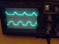
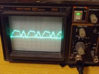
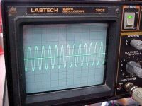
It looks like almost perfect ZCS operation. On low power run I got 3.3 Vin tank voltage as predicted, and on 24V it hits 100V (some 4 Vin ).
Maybe I need to adjust coupling a bit more.
It's 500ns div (freq about 1,4Mhz), gate voltage is 10Vdiv, DS voltage (sine) is 50V div.
ClassE stage supply is 16V.
Marko, Wed Jul 05 2006, 02:17PM
OK, here it is


I was very suprised to see the coil break out from it's topload in CW at such low power input.
I updated my post in
 after I got my camera working again with waveforms and stuff.
It looks like almost perfect ZCS operation. On low power run I got 3.3 Vin tank voltage as predicted, and on 24V it hits 100V (some 4 Vin ).
Maybe I need to adjust coupling a bit more.
It's 500ns div (freq about 1,4Mhz), gate voltage is 10Vdiv, DS voltage (sine) is 50V div.
ClassE stage supply is 16V.


Re: Class E SSTC thread
ragnar, Thu Jul 06 2006, 02:56AM
For the power supply, if you're feeling bored and inventive, you might consider building a big solid-state marxgen / charge pump. =P
i.e. charge caps in parallel, switch FETs to put them in series through your load... I'm gonna get flamed for this one. ^^
ragnar, Thu Jul 06 2006, 02:56AM
For the power supply, if you're feeling bored and inventive, you might consider building a big solid-state marxgen / charge pump. =P
i.e. charge caps in parallel, switch FETs to put them in series through your load... I'm gonna get flamed for this one. ^^
Re: Class E SSTC thread
ragnar, Thu Jul 06 2006, 09:53AM
Hehe, I admire your oscilloscope
I realised that I'd forgotten how elegant class-E was, so I just made a little lashup today with a single isodriver of mine (substituting a diode for the shunt capacitor).
Will write more soon =)
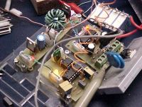
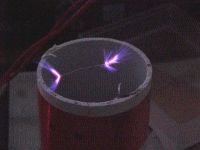
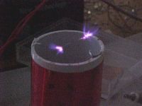
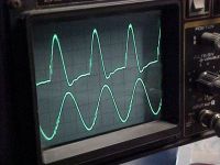
ragnar, Thu Jul 06 2006, 09:53AM
Hehe, I admire your oscilloscope

I realised that I'd forgotten how elegant class-E was, so I just made a little lashup today with a single isodriver of mine (substituting a diode for the shunt capacitor).
Will write more soon =)


Re: Class E SSTC thread
WaveRider, Thu Jul 06 2006, 01:09PM
Goodonya BP and Firkragg... I've been lurking a bit and your work is looking great!!!
(I'll try to get back to class-E stuff this autumn...too much other work at the moment!...)
WaveRider, Thu Jul 06 2006, 01:09PM
Goodonya BP and Firkragg... I've been lurking a bit and your work is looking great!!!
(I'll try to get back to class-E stuff this autumn...too much other work at the moment!...)
Re: Class E SSTC thread
Marko, Thu Jul 06 2006, 01:12PM
Looks good bp, I hope you'l give more specs soon.
I'd say this is very good if input voltage is 12..15V.
Class E is somewhat frustrating because you must always do everything to suit output amplifier, you have to reduce coupling even if higher one makes longer sparks, tune it for streame/no streamer and etc.
Big plus is posibillity of running cheap MOSFETs on very high frequencies.
All that isolation you have is probably unnecessary for class E (since there is only one fet).
I don't know if I should include a small GDT for isolation in my circuit..
Currently I was trying to make a transformer for power supply, but I had bg trouble getting it apart.
I cooked out a hell of small ATX power transformer but ther was too much epoxy.
I guess I'l have to use the transformer in it's current state (means ZVS).
I'l have to add a 'SS variac' separately
For now I can trygiving the coil more power, I can double a bigger 24V transformer to 60V (i'm a bit scared t blow it up now, and especially for gate driver wich I have only limited supply)
Also BP, are you running your gates a bit sine? Or that's some other signal?
Guessing upper is DS voltage your class E looks pretty good.
A solid-state powered Cockroft Walton is how very efficient solid state step-up converters are made. But it's not practical for my app.
Marx would be possible but it would require a lot more switching devices..
Marko, Thu Jul 06 2006, 01:12PM
Looks good bp, I hope you'l give more specs soon.
I'd say this is very good if input voltage is 12..15V.
Class E is somewhat frustrating because you must always do everything to suit output amplifier, you have to reduce coupling even if higher one makes longer sparks, tune it for streame/no streamer and etc.
Big plus is posibillity of running cheap MOSFETs on very high frequencies.
All that isolation you have is probably unnecessary for class E (since there is only one fet).
I don't know if I should include a small GDT for isolation in my circuit..
Currently I was trying to make a transformer for power supply, but I had bg trouble getting it apart.
I cooked out a hell of small ATX power transformer but ther was too much epoxy.
I guess I'l have to use the transformer in it's current state (means ZVS).
I'l have to add a 'SS variac' separately

For now I can trygiving the coil more power, I can double a bigger 24V transformer to 60V (i'm a bit scared t blow it up now, and especially for gate driver wich I have only limited supply)
Also BP, are you running your gates a bit sine? Or that's some other signal?
Guessing upper is DS voltage your class E looks pretty good.
For the power supply, if you're feeling bored and inventive, you might consider building a big solid-state marxgen / charge pump. =P
i.e. charge caps in parallel, switch FETs to put them in series through your load... I'm gonna get flamed for this one. ^^
A solid-state powered Cockroft Walton is how very efficient solid state step-up converters are made. But it's not practical for my app.
Marx would be possible but it would require a lot more switching devices..

Re: Class E SSTC thread
ragnar, Thu Jul 06 2006, 01:51PM
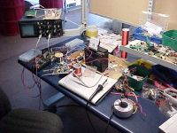
hehe, I've seen identical Hung Chang and Labtech 3502 oscilloscopes before.... Hung Chang was there first, right?
Tomorrow I'll be clearing up some mess, doubling my gate-drive power, possibly doubling my frequency, and then doubling the voltage swing by making a two-ended class-E drive.. And it'll probably result in quadrupled silicon deaths. =D
I daren't push these little IRF830s any harder... ^^
hmm, I wonder if that little spike in my DS waveform corresponds to the same miller spike in my GS waveform.
ragnar, Thu Jul 06 2006, 01:51PM
hehe, I've seen identical Hung Chang and Labtech 3502 oscilloscopes before.... Hung Chang was there first, right?

Tomorrow I'll be clearing up some mess, doubling my gate-drive power, possibly doubling my frequency, and then doubling the voltage swing by making a two-ended class-E drive.. And it'll probably result in quadrupled silicon deaths. =D
I daren't push these little IRF830s any harder... ^^
hmm, I wonder if that little spike in my DS waveform corresponds to the same miller spike in my GS waveform.

Re: Class E SSTC thread
Marko, Thu Jul 06 2006, 02:09PM
I see you are going to sleep now
And I realized about your scope before...
I built a double ended-driven coil too but spark wasnt't actually 2x big. But it can indeed help you to put more power into resonator. What input voltage/power is he currently running at?
EDIT: I've testedmy current ZVS driver circuit on ATX transformer as it was, but I was unable to get desired voltage output. (ofcourse).
I could get 200V AC minimum, and it is pretty stable, when loaded with 40W bulkb it drops for just few volts. To bad I need some 120V or less as maximum at full power.
Epoxy is too hard and I could never get the core apart without destroying it
I'l have to find something else around...
,
Marko, Thu Jul 06 2006, 02:09PM
I see you are going to sleep now

And I realized about your scope before...
I built a double ended-driven coil too but spark wasnt't actually 2x big. But it can indeed help you to put more power into resonator. What input voltage/power is he currently running at?
EDIT: I've testedmy current ZVS driver circuit on ATX transformer as it was, but I was unable to get desired voltage output. (ofcourse).
I could get 200V AC minimum, and it is pretty stable, when loaded with 40W bulkb it drops for just few volts. To bad I need some 120V or less as maximum at full power.
Epoxy is too hard and I could never get the core apart without destroying it

I'l have to find something else around...
,
Re: Class E SSTC thread
liquidFire, Thu Jul 06 2006, 10:19PM
I've done a similar thing last winter, it's a rather small class-E coil with on board power supply, all powered by a 12V battery. I thought about wearing that thing as a hat, but I think there will be a grounding problem then...
The PCB is 100 x 120mm and contains all needed parts, including the secondary.
It's a very simple boost converter that powers the class E amp and it's not running very stable, but good enough for a tesla coil.
Picture 1
Picture 2
Schematic
Video using some audio modulation
liquidFire, Thu Jul 06 2006, 10:19PM
Firkragg wrote ...
I want it to be portable and power it from an external 12..15V source, and I don't mind dragging big mains transformers around or within the coil.
I always wanted to have a power supply inside the coil, wich would be on a relatively small board (not more than about 4*8cm) and provide voltages required for class E stage.
It would need to produce about 100 watts, and nice thing would be if I could regulate it somehow (0-150volts)
I've done a similar thing last winter, it's a rather small class-E coil with on board power supply, all powered by a 12V battery. I thought about wearing that thing as a hat, but I think there will be a grounding problem then...
The PCB is 100 x 120mm and contains all needed parts, including the secondary.
It's a very simple boost converter that powers the class E amp and it's not running very stable, but good enough for a tesla coil.
Picture 1
Picture 2
Schematic
Video using some audio modulation
Re: Class E SSTC thread
ragnar, Fri Jul 07 2006, 03:11AM
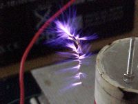
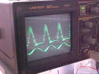
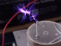
We all love pics.. so, err, here, have some pics. =-D
I've been carefully raising the volts this morning from 12V to 19V to 25V to 50V, and now he's drawing about 4A w/ tightish coupling but too little loading capacitance, from the looks of the scope? eee.... at least my heatsink stays cold.
Maybe I should throw an RF choke in there for the hell of it... and more power supply decoupling -- I only have 2.72uF of decoupling caps on there, hehe


Re: Class E SSTC thread
..., Fri Jul 07 2006, 03:13AM
ooh, sparkzzz
How long are they if moved to a single breakout point?
How is the fet holidng up?
..., Fri Jul 07 2006, 03:13AM
ooh, sparkzzz
How long are they if moved to a single breakout point?
How is the fet holidng up?
Re: Class E SSTC thread
WaveRider, Fri Jul 07 2006, 08:26AM
The tiny spike on the left side of your waveform is likely a little bit of harmonic generation going on as a result of parasitic resonance somewhere in your circuit. Likewise, the "undershoot" on the right side of each "half-sine" could be the result voltage drop across a little bit of parasitic lead inductance during a short period of "reverse current" flowing through the drain. (This figure is from a plot of a Spice simulation of a class-E amplifier...note the reverse drain current that flows for a short time during the transistor turn-on stage... parasitic lead inductance was not included in the simulation, so the voltage waveform does show this effect. Perhaps, if I had included a couple of nH of lead inductance, this reverse voltage would appear, like it does in your o-scope measurement....)

The origin of this current appears to be indeed due charging of the gate-drain capacitance during transistor turn-on (Cgd). Initially, I would not have expected the current transient to be so large.... However, if one estimates the charge moved during the transient, it comes to about 75nC...which is wthin the same order of magnitude of the data-sheet specified Miller charge for this transistor (2SK2698: 22nC for Vdd=400V, Vgs=10V, Id=15A...my simulation conditions:estimate 75nC for Vdd=0V, Vgs=12V, Id=0A).
EDIT:
BP: In your post where you increase the supply voltage, you look like you are getting lots of high-order harmonic generation. A little bit of quenching resistance may be in order in the gate circuit to kill those high frequency components.. (I could just be blowing hot air out my arse too, given I don't even know what your circuit looks like or if it's your o-scope probes that are resonating! )
)
WaveRider, Fri Jul 07 2006, 08:26AM
BP wrote ...
hmm, I wonder if that little spike in my DS waveform corresponds to the same miller spike in my GS waveform.
hmm, I wonder if that little spike in my DS waveform corresponds to the same miller spike in my GS waveform.
The tiny spike on the left side of your waveform is likely a little bit of harmonic generation going on as a result of parasitic resonance somewhere in your circuit. Likewise, the "undershoot" on the right side of each "half-sine" could be the result voltage drop across a little bit of parasitic lead inductance during a short period of "reverse current" flowing through the drain. (This figure is from a plot of a Spice simulation of a class-E amplifier...note the reverse drain current that flows for a short time during the transistor turn-on stage... parasitic lead inductance was not included in the simulation, so the voltage waveform does show this effect. Perhaps, if I had included a couple of nH of lead inductance, this reverse voltage would appear, like it does in your o-scope measurement....)

The origin of this current appears to be indeed due charging of the gate-drain capacitance during transistor turn-on (Cgd). Initially, I would not have expected the current transient to be so large.... However, if one estimates the charge moved during the transient, it comes to about 75nC...which is wthin the same order of magnitude of the data-sheet specified Miller charge for this transistor (2SK2698: 22nC for Vdd=400V, Vgs=10V, Id=15A...my simulation conditions:estimate 75nC for Vdd=0V, Vgs=12V, Id=0A).
EDIT:
BP: In your post where you increase the supply voltage, you look like you are getting lots of high-order harmonic generation. A little bit of quenching resistance may be in order in the gate circuit to kill those high frequency components.. (I could just be blowing hot air out my arse too, given I don't even know what your circuit looks like or if it's your o-scope probes that are resonating!
 )
)Re: Class E SSTC thread
Steve Conner, Fri Jul 07 2006, 08:56AM
I think the undershoots are caused by mismatching in such a way that the drain current is underdamped and tries to shoot below zero. Richie's Class-E page explains all. But they don't seem too drastic and it all seems to be performing well. I don't think the RF choke or extra decoupling would make much difference.
Steve Conner, Fri Jul 07 2006, 08:56AM
I think the undershoots are caused by mismatching in such a way that the drain current is underdamped and tries to shoot below zero. Richie's Class-E page explains all. But they don't seem too drastic and it all seems to be performing well.
 I don't think the RF choke or extra decoupling would make much difference.
Re: Class E SSTC thread
WaveRider, Fri Jul 07 2006, 09:21AM
Steve, this simulation is not for a tesla coil, but for a matched-to-50-ohms class-E amplifier (perhaps I should have said so..sorry!) Any class-E output matching circuit is going to be slightly underdamped (Q of 2-5 or so) because by definition, it relies on "ringing" at the fundamental frequency to define the transistor turn-on and turn-off times.
I don't think the body-diode was forced into conduction in the simulations during the reverse current times, because Vds was very close to zero. What is happening in reality, may be another matter! ;)
The RF choke may help reduce coupling to power leads if you're having problems related to interference (I used one for mine, because RF coupling to power leads in my 4.5MHz coil caused the digital meters on my bench power supply to go insane, the gas heater's computer to lock up and the kitchen clock to freak out....)
Re: Class E SSTC thread
Marko, Fri Jul 07 2006, 02:11PM
Great little coil liquidfire
And welcome to (new) 4HV..
I decided to use mazzili driver controlled by external PWM regulator. I got an inspiration for this from some small CCFL inverters wich use similar topology (mazzili/royer powers a transformer efficiently and it is externally controlled by additional PWM IC.
IC eventually takes feedback from oscillator's output.
Now I got into a big trouble finding an adequate transformer for ZVS.
Untouched ATX transformer works but can't generate low enough output voltage for input power.
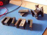
Firstly I tried to get the core apart by throwing the transformer in boiling water, but it wasn't even lcose to weaken the epoxy.
I had to heat up the transformer to 300+ degrees with hot air fan to let the core go.
Ferrite forms microfractures when abused lik this and breaks easily.
I broke one core instantly, another I broke later handling it. Tiny cracks are everywhere and I don't think such cores are usable anymore.
I had a sized ferrite pot somewhere but I found it broken too (ages old thng).
Such things are to be bought (impossible in croatia). A bigger ferrite toroid would be even neater for use as I don't need lots of windings.
Looks neat bp, now it could be right time to put a small topload (a little toroid would look great on your small resonator) on it
Allows some extra sparks to be drawn, and even breaks out on it's own if coil is propertly made.
It must be a monster heatsink to dissipate 20 watts over there and stay cold.
Seeing your sparks I must admit they look a bit ghetto for 200 Watts of input power.
You should be kicking 4-5 cm streamers without, and maybe 10 with interrupter.
(look at steve ward's coil).
I should also put an interrupter to my coil if I want to pwn steve ward at some stage
For decoupling cap I used 0.68uF and it was fine. If you want to be sure about it just put a main filter cap on it's place.
You don't need RF chokes and such stuff, especially in series with your primary.
I tried to put a variable inductor there (with few turns of thick wire) but it just suffocated the output, and I couldn't tune class E stage with it noticeably so I removed it.
Steve, I think you also need a small class E coil like such.
Nothing on your site for long (OK we are expecting Odin here, soon )
)
Marko, Fri Jul 07 2006, 02:11PM
I've done a similar thing last winter, it's a rather small class-E coil with on board power supply, all powered by a 12V battery. I thought about wearing that thing as a hat, but I think there will be a grounding problem then...
The PCB is 100 x 120mm and contains all needed parts, including the secondary.
It's a very simple boost converter that powers the class E amp and it's not running very stable, but good enough for a tesla coil.
Great little coil liquidfire

And welcome to (new) 4HV..
I decided to use mazzili driver controlled by external PWM regulator. I got an inspiration for this from some small CCFL inverters wich use similar topology (mazzili/royer powers a transformer efficiently and it is externally controlled by additional PWM IC.
IC eventually takes feedback from oscillator's output.
Now I got into a big trouble finding an adequate transformer for ZVS.
Untouched ATX transformer works but can't generate low enough output voltage for input power.
Firstly I tried to get the core apart by throwing the transformer in boiling water, but it wasn't even lcose to weaken the epoxy.
I had to heat up the transformer to 300+ degrees with hot air fan to let the core go.
Ferrite forms microfractures when abused lik this and breaks easily.
I broke one core instantly, another I broke later handling it. Tiny cracks are everywhere and I don't think such cores are usable anymore.

I had a sized ferrite pot somewhere but I found it broken too (ages old thng).
Such things are to be bought (impossible in croatia). A bigger ferrite toroid would be even neater for use as I don't need lots of windings.

We all love pics.. so, err, here, have some pics. =-D
I've been carefully raising the volts this morning from 12V to 19V to 25V to 50V, and now he's drawing about 4A w/ tightish coupling but too little loading capacitance, from the looks of the scope? eee.... at least my heatsink stays cold.
Maybe I should throw an RF choke in there for the hell of it... and more power supply decoupling -- I only have 2.72uF of decoupling caps on there, hehe
Looks neat bp, now it could be right time to put a small topload (a little toroid would look great on your small resonator) on it

Allows some extra sparks to be drawn, and even breaks out on it's own if coil is propertly made.
It must be a monster heatsink to dissipate 20 watts over there and stay cold.
Seeing your sparks I must admit they look a bit ghetto for 200 Watts of input power.
You should be kicking 4-5 cm streamers without, and maybe 10 with interrupter.
(look at steve ward's coil).
I should also put an interrupter to my coil if I want to pwn steve ward at some stage

For decoupling cap I used 0.68uF and it was fine. If you want to be sure about it just put a main filter cap on it's place.
You don't need RF chokes and such stuff, especially in series with your primary.
I tried to put a variable inductor there (with few turns of thick wire) but it just suffocated the output, and I couldn't tune class E stage with it noticeably so I removed it.
I think the undershoots are caused by mismatching in such a way that the drain current is underdamped and tries to shoot below zero. Richie's Class-E page explains all. But they don't seem too drastic and it all seems to be performing well. I don't think the RF choke or extra decoupling would make much difference.
Steve, I think you also need a small class E coil like such.

Nothing on your site for long (OK we are expecting Odin here, soon
 )
)Re: Class E SSTC thread
Sulaiman, Fri Jul 07 2006, 02:34PM
I have experimented with a CFPR (zvs) 12V powered invertor,
Modulation is easy,
The easy/inefficient way is a linear regulator feeding the dc inductor,
(pMOSFET with a potentiometer +12V to 0V, wiper to gate for variable CURRENT)
Chopping the dc supply to the dc inductor with a pMOSFET and 555
gives output modulation (but with complex waveforms).
You should have fast diodes from 0V to drain and drain to +12V in either case.
I used 2 x NTP27N06 for the invertor and 1 x MTP23P06 for the chopper
not because they're the best, but because I was given a few by Adam Horden.
I used an MPP core for the dc inductor (similar to iron powder) which works VERY well
and gapped-ferrite for the resonant/invertor transformer.
If interrested I'll see if I can dig up the circuit and post some waveforms.
(I may have to reconstruct it so patience will be required)
P.S. For my relatively low frequency resonator (<100 kHz)
the CFPR inductance can be a few turns of copper tubing TC primary
but my 80W CW in a 6" dia 28" high secondary was not impressive.
(I used a 12V 7AH VRLA battery and MMKP capacitors)
P.P.S. A flyback invertor is easier.
Re: Class E SSTC thread
GimpyJoe, Fri Jul 07 2006, 03:09PM
I think even in Croatia you should be able to find black and white TV's. Just get the flyback out of one of those and pull out the core.
Also, I never heard you say anything about it needing to be battery-powered. You could try to find a little variac and then just rectify it.
What is the mains voltage in Croatia? If it's 230 you could just make a voltage divider and then rectify it.
Re: Class E SSTC thread
Marko, Fri Jul 07 2006, 04:46PM
Sulaiman:
Well I abandoned boost converter because of inefficiency. High voltage mosfets/IGBT's would dissipate too much power.
Flyback is neater because I can use low woltage, low Rds-ON mosfets for lower loss.
But it is hard switching and still relatively lossy. I also imagine trouble with matching the output.
Maybe it could later be improved to double-ended drive with deadtime control, etc.
*updated*
I don't think that 'interrupting' a ZVS would do any good, and putting additional buck seems pointless regarding efficiency.
By chopping gate supplies or main power I only get wierd waveform wich is difficult to modulate, and I put stress to ZVS unless I sinchronize turn-offs.
I have some SG3525-s here anyway, so the'l be put to use.
Im' definitely not going to drag a vaiac with this (even smallest I seen are 2x times bigger than the coil itself). Powering the coil from 220V would again be inadequate as I would need a 'big' mains transformer to powr electronics. It swould be just silly to see all that to be dragged together with such a tiny coil.
Even smallest flyback cores I have would hardly fit onto my power supply board, but I *could* mock out something of them too if I get really desperate. They are really an overkill for the power level I use.
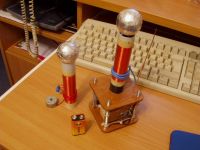
This is an older pic of the coil, it wasn't even class-E at that time and was rather of ghetto internalconstruction, but general look is the same
Edited:
omg sparks:
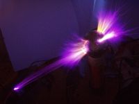
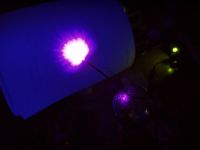
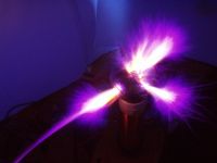
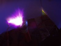
I finally gave the coil some more power, this time it is 45 volts at some 70 watts.
If I put a breakout point onto the coil It spews about 6 cm wide streamer.
Arc hits 11cm as maximum (I admit I now had some more starting voltage, about 60 volts) but it disconnects and continues to live as beautiful brushy streamer breaking out on itself from topload. Coil sometimes breaks out from topload on it's own.
Electric field from the topload causes interesting 'pinch' effect to the plasma, and about 2 cm from topload it keeps narrow beam wich is incredibly hot, looking like bright yellow flame.
Then it forms branches like 'standard' CW streamers.
I have to disconnect the coil from supply if that streamer settles in place, as it would make celluloid ball explode if it settles too long in one place.
I definitely need a better topload =)
When I bring the wire closer I can draw very hot, flame-like arc wich is about 6cm long.
I also heated out a hell of small heatsink, after few minutes mosfet easily reaches boiling point. Now I just need an interrupter and a little more input power...
Marko, Fri Jul 07 2006, 04:46PM
Sulaiman:
Well I abandoned boost converter because of inefficiency. High voltage mosfets/IGBT's would dissipate too much power.
Flyback is neater because I can use low woltage, low Rds-ON mosfets for lower loss.
But it is hard switching and still relatively lossy. I also imagine trouble with matching the output.
Maybe it could later be improved to double-ended drive with deadtime control, etc.
*updated*
I don't think that 'interrupting' a ZVS would do any good, and putting additional buck seems pointless regarding efficiency.
By chopping gate supplies or main power I only get wierd waveform wich is difficult to modulate, and I put stress to ZVS unless I sinchronize turn-offs.
I have some SG3525-s here anyway, so the'l be put to use.

I think even in Croatia you should be able to find black and white TV's. Just get the flyback out of one of those and pull out the core.
Also, I never heard you say anything about it needing to be battery-powered. You could try to find a little variac and then just rectify it.
What is the mains voltage in Croatia? If it's 230 you could just make a voltage divider and then rectify it.
Im' definitely not going to drag a vaiac with this (even smallest I seen are 2x times bigger than the coil itself). Powering the coil from 220V would again be inadequate as I would need a 'big' mains transformer to powr electronics. It swould be just silly to see all that to be dragged together with such a tiny coil.
Even smallest flyback cores I have would hardly fit onto my power supply board, but I *could* mock out something of them too if I get really desperate. They are really an overkill for the power level I use.
This is an older pic of the coil, it wasn't even class-E at that time and was rather of ghetto internalconstruction, but general look is the same


Edited:
omg sparks:


I finally gave the coil some more power, this time it is 45 volts at some 70 watts.
If I put a breakout point onto the coil It spews about 6 cm wide streamer.
Arc hits 11cm as maximum (I admit I now had some more starting voltage, about 60 volts) but it disconnects and continues to live as beautiful brushy streamer breaking out on itself from topload. Coil sometimes breaks out from topload on it's own.
Electric field from the topload causes interesting 'pinch' effect to the plasma, and about 2 cm from topload it keeps narrow beam wich is incredibly hot, looking like bright yellow flame.
Then it forms branches like 'standard' CW streamers.
I have to disconnect the coil from supply if that streamer settles in place, as it would make celluloid ball explode if it settles too long in one place.
I definitely need a better topload =)
When I bring the wire closer I can draw very hot, flame-like arc wich is about 6cm long.
I also heated out a hell of small heatsink, after few minutes mosfet easily reaches boiling point. Now I just need an interrupter and a little more input power...
Re: Class E SSTC thread
Steve Conner, Fri Jul 07 2006, 10:37PM
Hey Firkragg
That looks great! What frequency does it work at?
BTW, I think a ZVS with a buck converter before it isn't such a bad idea as it sounds. If you used the 12V winding on an ATX transformer as the primary, it could get you into the 150V ball park. I once tried a ZVS using the 5v winding as the primary, and the output gave 300-350V DC when rectified (with a voltage doubler iirc)
And of course the buck converter lets you regulate the output.
Steve Conner, Fri Jul 07 2006, 10:37PM
Hey Firkragg
That looks great!
 What frequency does it work at?
BTW, I think a ZVS with a buck converter before it isn't such a bad idea as it sounds. If you used the 12V winding on an ATX transformer as the primary, it could get you into the 150V ball park. I once tried a ZVS using the 5v winding as the primary, and the output gave 300-350V DC when rectified (with a voltage doubler iirc)
And of course the buck converter lets you regulate the output.
Re: Class E SSTC thread
Marko, Fri Jul 07 2006, 10:57PM
I scoped everything and ATX transformer simply doesn't fit my desires
From 12V winding I got some 200V from that wierd transformer.
Problem with ZVS is that resonant rise givesme about 35V on primary (measured) and ratio of ATX transformer is simply too high.
Autopsy showed about 7 turns on each primary wich is way too much for 12V input voltage and some reasonable power/frequency.
I would rather need something like 1:3 transformer for this, with low number of primary turns to maximize power output.
When I add a buck converter it becomes pretty lossy and I have no advantage over flyback converter (maybe I do a little, snubbing is not needed ans so.)
Coil is operating at 1.4Mhz, wich may drop a bit with huge streamer loading.
I need to dinamically tune class E stage now
Next will be adding an interruper and casting a ball out of poliester, I really don't want that ceelluloid ball to die again
PS:
Steve, if I remember there was a 'controversy' about your PLL circuit (I'm using it in this coil) that it goes nuts and cannot lock if interrupter cicles are too short.
So am I going to have trouble with it, or I can get away using inhibit or audiomod input to 'turn off' VCO itself?
Maybe best for me to find out myself.. tommorow..
Marko, Fri Jul 07 2006, 10:57PM
Hey Firkragg
That looks great! What frequency 'as is' does it work at?
BTW, I think a ZVS with a buck converter before it isn't such a bad idea as it sounds. If you used the 12V winding on an ATX transformer as the primary, it could get you into the 150V ball park. I once tried a ZVS using the 5v winding as the primary, and the output gave 300-350V DC when rectified (with a voltage doubler iirc)
And of course the buck converter lets you regulate the output.
I scoped everything and ATX transformer simply doesn't fit my desires

From 12V winding I got some 200V from that wierd transformer.
Problem with ZVS is that resonant rise givesme about 35V on primary (measured) and ratio of ATX transformer is simply too high.
Autopsy showed about 7 turns on each primary wich is way too much for 12V input voltage and some reasonable power/frequency.
I would rather need something like 1:3 transformer for this, with low number of primary turns to maximize power output.
When I add a buck converter it becomes pretty lossy and I have no advantage over flyback converter
 (maybe I do a little, snubbing is not needed ans so.)
Coil is operating at 1.4Mhz, wich may drop a bit with huge streamer loading.
I need to dinamically tune class E stage now

Next will be adding an interruper and casting a ball out of poliester, I really don't want that ceelluloid ball to die again

PS:
Steve, if I remember there was a 'controversy' about your PLL circuit (I'm using it in this coil) that it goes nuts and cannot lock if interrupter cicles are too short.
So am I going to have trouble with it, or I can get away using inhibit or audiomod input to 'turn off' VCO itself?
Maybe best for me to find out myself.. tommorow..
Re: Class E SSTC thread
liquidFire, Sat Jul 08 2006, 12:10AM

Your coil looks very cool, I realy like it.
With regulation, I get the 50 to 95V that I want.
Maybe you could use a similar regulation to limit the output of your converter, just use a few-hundred µF cap, and then switch the converter on and off, depending on the cap voltage. It's not the best way to get a regulated output, but it's simple and good enough for a TC.
liquidFire, Sat Jul 08 2006, 12:10AM
Firkragg wrote ...
Great little coil liquidfire
And welcome to (new) 4HV..
Thanks a lot! Great little coil liquidfire

And welcome to (new) 4HV..

Your coil looks very cool, I realy like it.
Firkragg wrote ...
From 12V winding I got some 200V from that wierd transformer.
Problem with ZVS is that resonant rise givesme about 35V on primary (measured) and ratio of ATX transformer is simply too high.
Autopsy showed about 7 turns on each primary wich is way too much for 12V input voltage and some reasonable power/frequency.
I get a little bit more than 120V out of my boost converter, running without regulation.From 12V winding I got some 200V from that wierd transformer.
Problem with ZVS is that resonant rise givesme about 35V on primary (measured) and ratio of ATX transformer is simply too high.
Autopsy showed about 7 turns on each primary wich is way too much for 12V input voltage and some reasonable power/frequency.
With regulation, I get the 50 to 95V that I want.
Maybe you could use a similar regulation to limit the output of your converter, just use a few-hundred µF cap, and then switch the converter on and off, depending on the cap voltage. It's not the best way to get a regulated output, but it's simple and good enough for a TC.
Re: Class E SSTC thread
Marko, Sat Jul 08 2006, 12:19AM
PWM regulation isn't a problem with buck, boost or flyback converter and etc.
Point was that making a self-oscillating ZVS driver (wich is very efficient and cannot be regulated) and then regulating it with buck converter wouldn't be practical in this app.
It's better to use something like simple flyback converter or so.
Re: Class E SSTC thread
Steve Conner, Sat Jul 08 2006, 09:16AM
Hi Firkragg
I tested my Mk.1 PLL circuit with an ordinary SSTC running off a big 300V DC filter cap and an interrupter. It seemed to work fine. I think it only causes trouble with DRSSTCs because their pulses are much shorter. Steve Ward actually made a modified version of my Mk.1 circuit, so if you have trouble with the original, but still want a PLL, you might want to try his. I think he took the circuit from my Mk2 driver that helps it lock on short bursts, and threw away all the other complicated stuff.

Re: Class E SSTC thread
Marko, Sat Jul 08 2006, 12:21PM
I'l settle this out then.
One more thing here is that I brought back antenna feedback again for higher power shots, looks more reliable for now.
Base current feedback does something strange, when spark loads the coil it detunes and if I disconnect power supply PLL locks to another harmonic of the coil (yes sparks are that big)
I need to increase VCOin voltage again to restore the oscillation, and then flip it back while coil is working to get maximum spark.
Transformer I used was lashy from some old monitor, I guess I should strenghten the feedback by using better transformer.
I'm using 100nF DC blocking cap and 10k burden resistor to ground, to reject noise.
Another transformer I tried woked better (but was clumsy) so I guess problem is there.
Marko, Sat Jul 08 2006, 12:21PM
I'l settle this out then.
One more thing here is that I brought back antenna feedback again for higher power shots, looks more reliable for now.
Base current feedback does something strange, when spark loads the coil it detunes and if I disconnect power supply PLL locks to another harmonic of the coil
 (yes sparks are that big)
I need to increase VCOin voltage again to restore the oscillation, and then flip it back while coil is working to get maximum spark.
Transformer I used was lashy from some old monitor, I guess I should strenghten the feedback by using better transformer.
I'm using 100nF DC blocking cap and 10k burden resistor to ground, to reject noise.
Another transformer I tried woked better (but was clumsy) so I guess problem is there.
Re: Class E SSTC thread
ragnar, Sat Jul 08 2006, 01:01PM
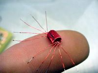
Exhibit A) World's smallest gate-driver transformer wound around a ferrite bead (for small 2N7000 MOSFETs) with 0.15mm enamelled copper wire. I'll explain this one later. Yes, that bead is about 4mm tall.
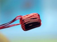
Exhibit B) Resonator with fundamental frequency of 3.45MHz wound around 25mm PVC pipe, pictured next to a 7KG reel of the 0.15mm wire used to wind it.
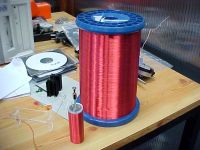
Exhibit C) Breakout from the screwy (ha ha) topload at 25Vin 1.5A
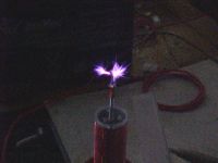
Exhibit D) Top waveform is D/S shunt capacitor voltage, bottom waveform is my scope probe hanging near the top of the secondary.
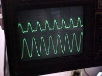
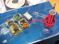
Exhibit E) The whole mess not really doing much whilst I design a more powerful gatedriver. The isodriver is approching his limits.. =)
ragnar, Sat Jul 08 2006, 01:01PM
Exhibit A) World's smallest gate-driver transformer wound around a ferrite bead (for small 2N7000 MOSFETs) with 0.15mm enamelled copper wire. I'll explain this one later. Yes, that bead is about 4mm tall.

Exhibit B) Resonator with fundamental frequency of 3.45MHz wound around 25mm PVC pipe, pictured next to a 7KG reel of the 0.15mm wire used to wind it.

Exhibit C) Breakout from the screwy (ha ha) topload at 25Vin 1.5A

Exhibit D) Top waveform is D/S shunt capacitor voltage, bottom waveform is my scope probe hanging near the top of the secondary.

Exhibit E) The whole mess not really doing much whilst I design a more powerful gatedriver. The isodriver is approching his limits.. =)

Re: Class E SSTC thread
Marko, Sat Jul 08 2006, 01:17PM
I was about to make my own GDT (for main mosfet) but I'm unsure if it is needed actually.
It may just cause ringing and mess.
Sine input at gate is actually good for class E amp, richieburnett used 2 stage class E driver (almost completely sine signal was fed to main mosfet's gate) and he used the amp for 300+ watts without problems.
Your spark looks good but I wouldn't actually call that screw 'topload', it has sharp corners

And I admire your roll of wire, where do you get all that stuff...
I see you cared a lot about your tnak cap, mine is nothing to be desired (puny 10nf ceramic cap wich is probably way overrated and gets very hot).
Are these high voltage 1nf caps?
Marko, Sat Jul 08 2006, 01:17PM
I was about to make my own GDT (for main mosfet) but I'm unsure if it is needed actually.
It may just cause ringing and mess.
Sine input at gate is actually good for class E amp, richieburnett used 2 stage class E driver (almost completely sine signal was fed to main mosfet's gate) and he used the amp for 300+ watts without problems.
Your spark looks good but I wouldn't actually call that screw 'topload', it has sharp corners


And I admire your roll of wire, where do you get all that stuff...

I see you cared a lot about your tnak cap, mine is nothing to be desired
 (puny 10nf ceramic cap wich is probably way overrated and gets very hot).
Are these high voltage 1nf caps?
Re: Class E SSTC thread
ragnar, Sat Jul 08 2006, 01:34PM
They're 250pF 10kV caps, the only caps that small I've got that aren't 50V ceramics. hehe ^^
I've got them configured to give me a 375nF shunt.
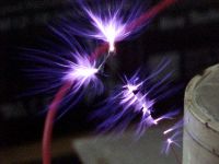
Screwy is just masquerading as a topload, the idea being if I want a topload I can bolt it on easily. For now, he just stops the coil breaking out at the edges.


Re: Class E SSTC thread
Marko, Sat Jul 08 2006, 02:54PM
I just filled a ping-pong ball with poliester, it must be dried before I put it to use as topload.
The one I was currently using already started buldging and I don't want it to die again.
^^this means coil waits for a while now.
Maybe you could make yourself something similar I see you have acces to various CNC machines over there.
What is your current max-spark length?
Marko, Sat Jul 08 2006, 02:54PM
I just filled a ping-pong ball with poliester, it must be dried before I put it to use as topload.
The one I was currently using already started buldging and I don't want it to die again.
^^this means coil waits for a while now.
Maybe you could make yourself something similar
 I see you have acces to various CNC machines over there.
What is your current max-spark length?
Re: Class E SSTC thread
GimpyJoe, Sat Jul 08 2006, 04:46PM
I had a ping-pong ball catch fire once. That was impressive. I was playing with a jacob's ladder and my friend said "if you put a pingpong ball in there will the arc go around it in a curve?" So we tried it and it burst into flames a foot tall and burned away into a little tiny pile of soot.
Back to the topic, however; you could use a metal drawer pull instead of the ping-pong ball for a topload. You could also just make an actual ball of foil. I made a topload for one of my early coils that was just a bunch of foil compressed and smoothed until it was almost a solid chunk of aluminum, then worked with a small hammer until it was round.
Re: Class E SSTC thread
Marko, Sat Jul 08 2006, 11:40PM
Yeah, and it is many times worse if ball burns under the foil with weak presence of oxygen.
Stink/smoke bombs are made like that :p
Poliester ball I made dried out.
I simply brought it outside and ignited ping-pong ball mold. It didn't smoke much since it had enough air to burn.
Then I just sanded the remaining carbon off the poliester ball.
I also had to repair some 'imperfections' additionally so it's drying now =)
And yes, I definitely need to fnd a better tank cap for this coil...
hehe
PS. thanks, Steve, for info..
Marko, Sat Jul 08 2006, 11:40PM
Yeah, and it is many times worse if ball burns under the foil with weak presence of oxygen.
Stink/smoke bombs are made like that :p
Poliester ball I made dried out.
I simply brought it outside and ignited ping-pong ball mold. It didn't smoke much since it had enough air to burn.
Then I just sanded the remaining carbon off the poliester ball.
I also had to repair some 'imperfections' additionally so it's drying now =)
And yes, I definitely need to fnd a better tank cap for this coil...

hehe
PS. thanks, Steve, for info..
Re: Class E SSTC thread
ragnar, Sun Jul 09 2006, 06:35AM
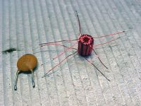
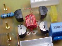
You'll either think this is some kind of sick joke, or that I'm a masochist, or that I'm bored. Either way, it's too late. Here's the gatedriver: =P
Let's see if I can get a little less dissipation in ze FET now.. ^^
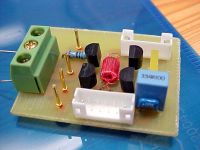
ragnar, Sun Jul 09 2006, 06:35AM
You'll either think this is some kind of sick joke, or that I'm a masochist, or that I'm bored. Either way, it's too late. Here's the gatedriver: =P
Let's see if I can get a little less dissipation in ze FET now.. ^^


Re: Class E SSTC thread
Marko, Sun Jul 09 2006, 02:05PM
What would be the real use of such a 'full bridge' of tiny FET's?
Marko, Sun Jul 09 2006, 02:05PM
What would be the real use of such a 'full bridge' of tiny FET's?
Re: Class E SSTC thread
Steve Conner, Sun Jul 09 2006, 02:30PM
Maybe he tried it just to see if it would work. I think it's pretty cool actually, whether it's any use or not. I guess it's some sort of gate driver for a larger FET.
Steve Conner, Sun Jul 09 2006, 02:30PM
Maybe he tried it just to see if it would work. I think it's pretty cool actually, whether it's any use or not. I guess it's some sort of gate driver for a larger FET.
Re: Class E SSTC thread
Marko, Sun Jul 09 2006, 03:39PM
I sanded away remaining carbon from the poliester ball, and prepared t to be taped...
Coil worked like nuts now, topload doesn't look good like before but it's functional at least.
Another great news is that I managed to overheat the mosfet.
I blame the poor ceramic cap I tortured over there, I definitely need replacement (it is just wonderful that 100V cap survived 200V peaks, probably he healed due to enormous currents after each breech).
What I seek now is to get 15cm sparks (and hopefully best Steve Ward's coil finally )
)
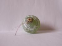
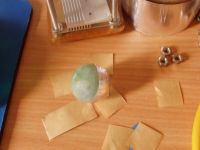
I replaced the mosfet and got better cap. This time it is 10nF 2kV, I hope it won't trouble me anymore.
The biggest problem that terrors me now is that peak tank voltage swings up to some 430-450V, with only 50 input; I'm definitely running away there.maybe I should try to lower the number of primary turns to 2. I don't know if it is best matching foor primary but I hope to reduce peak voltage and spare mosfet's from dying.
Maybe I should even consider richie burnett's approach, wich means separating class E amp from the primary. This way I could make the amp work reliably and hopefully find best impedance match for secondary (?).
Marko, Sun Jul 09 2006, 03:39PM
I sanded away remaining carbon from the poliester ball, and prepared t to be taped...
Coil worked like nuts now, topload doesn't look good like before but it's functional at least.
Another great news is that I managed to overheat the mosfet.
I blame the poor ceramic cap I tortured over there, I definitely need replacement (it is just wonderful that 100V cap survived 200V peaks, probably he healed due to enormous currents after each breech).
What I seek now is to get 15cm sparks (and hopefully best Steve Ward's coil finally
 )
)

I replaced the mosfet and got better cap. This time it is 10nF 2kV, I hope it won't trouble me anymore.
The biggest problem that terrors me now is that peak tank voltage swings up to some 430-450V, with only 50 input; I'm definitely running away there.maybe I should try to lower the number of primary turns to 2. I don't know if it is best matching foor primary but I hope to reduce peak voltage and spare mosfet's from dying.
Maybe I should even consider richie burnett's approach, wich means separating class E amp from the primary. This way I could make the amp work reliably and hopefully find best impedance match for secondary (?).
Re: Class E SSTC thread
ragnar, Sun Jul 09 2006, 11:03PM
When running 50Vin I get peaks up to about 180V... if the amp is not well loaded you'll get very high drain voltage spikes. What's your coupling like?
ragnar, Sun Jul 09 2006, 11:03PM
When running 50Vin I get peaks up to about 180V... if the amp is not well loaded you'll get very high drain voltage spikes. What's your coupling like?
Re: Class E SSTC thread
Marko, Sun Jul 09 2006, 11:32PM
After some studying I realized that my tank voltage also hangs about 200 (and even less) volts in the beggining, and then climbs as mosfet and capacitor heat up (this new cap is even hotter than last one, I should find some MKP cap for this but I don't have any at hand )
)
Even massive HV ceramics don't behave too good..
I need to get sleep and research this tomorrow
My coupling is pretty high, too high acually (?).
Also, If I remove any breakout point and not let the coil break out from topload tank voltage also stays at some 190 - 180 V.
When huge arcs detune the coil it suddenly jumps to 'hot' 400 volts.
BP, what heatsink are you using and how hot does it get over etc. one minute with etc. 100W input power?
And what spark length you get, ofcourse?
Marko, Sun Jul 09 2006, 11:32PM
After some studying I realized that my tank voltage also hangs about 200 (and even less) volts in the beggining, and then climbs as mosfet and capacitor heat up (this new cap is even hotter than last one, I should find some MKP cap for this but I don't have any at hand
 )
)Even massive HV ceramics don't behave too good..
I need to get sleep and research this tomorrow

My coupling is pretty high, too high acually (?).
Also, If I remove any breakout point and not let the coil break out from topload tank voltage also stays at some 190 - 180 V.
When huge arcs detune the coil it suddenly jumps to 'hot' 400 volts.
BP, what heatsink are you using and how hot does it get over etc. one minute with etc. 100W input power?
And what spark length you get, ofcourse?

Re: Class E SSTC thread
ragnar, Mon Jul 10 2006, 04:02AM
Play with the coupling to see how it affects the spark loading and the class-E damping, you'll have to retune frequency as you go, but it'll help you optimize the dissipation in the FET.
On mine, the tank voltage rings up about twice as high when there's no breakout. As soon as breakout occurs, the Q goes down enough for critical damping at just ~200V with 50V in.
The heatsink I'm using is the same shiny aluminium stock seen in previous photos. He gets very warm after 30secs of operation, but the coil is always sputtering and I worry about shoot-through in the FET --- I need to shield the driver circuitry.
The max sparklength I can get is about 6cm, but whenever I do this the coil tends to breakout at the edge, burning the former, and the Q goes down too much that I lose the critical damping condition on the FET.
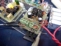
Speaking of FETs, stuff the 2N7000 fullbridge -- my IRFP460 is now driven as a matched resonant circuit with more UCCs. When I shield the driver electronics now, I think it'll be totally stable.
You like? =-)
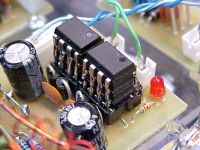


Re: Class E SSTC thread
rev, Mon Jul 10 2006, 05:05AM
i've though of "stacking" ucc's but never literaly stacking them mostly for issues of the ones to the center most over heating. seems to not be a problem.
rev, Mon Jul 10 2006, 05:05AM
i've though of "stacking" ucc's but never literaly stacking them mostly for issues of the ones to the center most over heating. seems to not be a problem.
Re: Class E SSTC thread
..., Mon Jul 10 2006, 05:57AM
it is somewhat common in the hifi cominuty to stack dac chips on top of eachother, but they are one step ahead of us... They put a little piece of copper/aluminum between each chip and then attach that to a heatsink on the side of the chips...
@BP as far as your problem with the coil breaking out at the top of the former... You can solve this by unwrapping a few turns at the top, then rewapping them in a loose spiral to the top of the former and then set a nice fat washer on top of that. Then stick a breakout point on top of that... If you don't want to retune with the extra topload you can omit the washer and just stick the breakout point on the side of the coil where the wire ends...
oh, and 6cm Somewhere I lost a sense of scale in your pics, I was thinking more like 2cm You are certinly beating my vttc efficiency (as close as I can come you your solid state leetness) of 12cm at 1.8kw
..., Mon Jul 10 2006, 05:57AM
it is somewhat common in the hifi cominuty to stack dac chips on top of eachother, but they are one step ahead of us... They put a little piece of copper/aluminum between each chip and then attach that to a heatsink on the side of the chips...
@BP as far as your problem with the coil breaking out at the top of the former... You can solve this by unwrapping a few turns at the top, then rewapping them in a loose spiral to the top of the former and then set a nice fat washer on top of that. Then stick a breakout point on top of that... If you don't want to retune with the extra topload you can omit the washer and just stick the breakout point on the side of the coil where the wire ends...
oh, and 6cm
 Somewhere I lost a sense of scale in your pics, I was thinking more like 2cm You are certinly beating my vttc efficiency (as close as I can come you your solid state leetness) of 12cm at 1.8kw
Re: Class E SSTC thread
Marko, Mon Jul 10 2006, 12:08PM
I actually don't think that some devil gatedrive is really important here.
Steve Ward ran his coil with 10 ohm gate esistor and everything seemed fine for him.
Your driver BP, could now drive a fullbridge of IGBT's without much problems
At least cou can't blame your gate driver for problems anymore :p
Thing that happens to me is pretty wierd and happens certainly as result of something_getting_hot, as I can replug the coil and still have about 400V DS voltage.
If I let the mosfet and cap cool down I can observe the effect again.
Voltage needs just few seconds to rise up to 400V, after some time it can get to 450+ and eventually cause death of the mosfet.
Small video of what actually goes on:
 (4.2mb)
Your heatsink is a bit bigger than mine but air-contact surface is about the same.
And my IRFP450 does also get very hot after some 30 sec's of continuous torture.
I don't know if this is too good but anyway in best case he has to dissipate some 10 watts
My current maxsparklength is 10-11cm for this coil, with something about 100W power input.
Anyway I can't get very stable arc since breakout continues on it's own from the topload.
I guess I would need an interrupter to mantain this and prevent streamers from sticking on the same spot and burning the topload.
You can see the sparks somewhere in the middle of the first page. Topload-streamers are also something about 6cm max long...
Marko, Mon Jul 10 2006, 12:08PM
I actually don't think that some devil gatedrive is really important here.
Steve Ward ran his coil with 10 ohm gate esistor and everything seemed fine for him.
Your driver BP, could now drive a fullbridge of IGBT's without much problems

At least cou can't blame your gate driver for problems anymore :p
Thing that happens to me is pretty wierd and happens certainly as result of something_getting_hot, as I can replug the coil and still have about 400V DS voltage.
If I let the mosfet and cap cool down I can observe the effect again.
Voltage needs just few seconds to rise up to 400V, after some time it can get to 450+ and eventually cause death of the mosfet.

Small video of what actually goes on:
 (4.2mb)
Your heatsink is a bit bigger than mine but air-contact surface is about the same.
And my IRFP450 does also get very hot after some 30 sec's of continuous torture.
I don't know if this is too good but anyway in best case he has to dissipate some 10 watts

oh, and 6cm Somewhere I lost a sense of scale in your pics, I was thinking more like 2cm You are certinly beating my vttc efficiency (as close as I can come you your solid state leetness) of 12cm at 1.8kw
My current maxsparklength is 10-11cm for this coil, with something about 100W power input.
Anyway I can't get very stable arc since breakout continues on it's own from the topload.
I guess I would need an interrupter to mantain this and prevent streamers from sticking on the same spot and burning the topload.
You can see the sparks somewhere in the middle of the first page. Topload-streamers are also something about 6cm max long...
Re: Class E SSTC thread
Steve Conner, Mon Jul 10 2006, 12:31PM
Some ceramic caps are designed to work in resonant circuits and take high RF voltages, and others are only really meant for bypassing and DC blocking. These latter types show drastic changes of capacitance with temperature (think a factor of 2). I guess this is what's happening with Firkragg's setup.
Re: Class E SSTC thread
Marko, Mon Jul 10 2006, 02:12PM
update1*
I found an adequate MKP 7,5nF, 1500V cap.
'rising' effect has gone and coil works like nuts now.
I get some 160-170V max no matter what I do.
Even 'fat looking' ceramic wasn't good for the job, but polypropylene/polycarbonate caps work pretty fine.
*me gives a bunch of geek points to Steve Conner again.
I'm not sure if capacitance is too low but it works very good with breakout point.
without breakout I get a massive overdamped waveform (a bit counter-intuitive).
update2*
This overdamping when coil is unloaded gets really annoying.
I want it to be somewhat stable with and without spark, and I can't find any eason why waveform looks like this then. It can't be just spark detuning since wavefoorm repairs to sine-ish again.
Interesting is that if there is a breakout I can keep high coupling and impedance match without making trouble.

I actually have no adequate theory for this yet.
I can guess this is just a trait of class E, that you can't give it enough coupling for nice sparks without punishing the driver.
Marko, Mon Jul 10 2006, 02:12PM
update1*
I found an adequate MKP 7,5nF, 1500V cap.
'rising' effect has gone and coil works like nuts now.
I get some 160-170V max no matter what I do.
Even 'fat looking' ceramic wasn't good for the job, but polypropylene/polycarbonate caps work pretty fine.
*me gives a bunch of geek points to Steve Conner again.
I'm not sure if capacitance is too low but it works very good with breakout point.
without breakout I get a massive overdamped waveform (a bit counter-intuitive).
update2*
This overdamping when coil is unloaded gets really annoying.
I want it to be somewhat stable with and without spark, and I can't find any eason why waveform looks like this then. It can't be just spark detuning since wavefoorm repairs to sine-ish again.
Interesting is that if there is a breakout I can keep high coupling and impedance match without making trouble.

I actually have no adequate theory for this yet.
I can guess this is just a trait of class E, that you can't give it enough coupling for nice sparks without punishing the driver.
Re: Class E SSTC thread
ragnar, Wed Jul 12 2006, 01:00AM
The 'devil' gate drive really is necessary -- I find the IRFP460 4.2nF gate capacitance very difficult to swing, even as a resonant circuit :P.
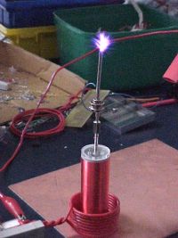
Here he is running at 3.55MHz, about 180W (50V in) with 5cm max breakout. The discharge is almost inaudible.
Very stable, but still not efficient enough for myyy liking.
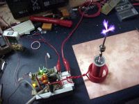
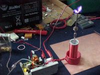
ragnar, Wed Jul 12 2006, 01:00AM
The 'devil' gate drive really is necessary -- I find the IRFP460 4.2nF gate capacitance very difficult to swing, even as a resonant circuit :P.
Here he is running at 3.55MHz, about 180W (50V in) with 5cm max breakout. The discharge is almost inaudible.

Very stable, but still not efficient enough for myyy liking.


Re: Class E SSTC thread
..., Wed Jul 12 2006, 04:30AM
wow bp, looks great! I think you need a longer topload though
..., Wed Jul 12 2006, 04:30AM
wow bp, looks great! I think you need a longer topload though

Re: Class E SSTC thread
Sulaiman, Wed Jul 12 2006, 06:18AM
Blackplasma,
is that a sheet of copper-clad board under the coil?
If it is, then I think replacing it with a non-conducting board would increase performance.
Sulaiman, Wed Jul 12 2006, 06:18AM
Blackplasma,
is that a sheet of copper-clad board under the coil?
If it is, then I think replacing it with a non-conducting board would increase performance.
Re: Class E SSTC thread
WaveRider, Wed Jul 12 2006, 10:52AM
Firkragg, if you have a good match when there is breakout, it is unlikely that there will be a match when there is no arc. With no breakout, your inductively coupled resonator is unloaded and will appear inductive (below resonance). Given the high-Q of the resonator, this corresponds to wide shifts in input impedance over small frequency excursions. Before breakout, you need to excite the coil with a frequency that is slightly higher than when it's running with an arc (plus...at startup, your driver must tolerate high voltages because of power reflected back from the unloaded resonator).. I believe the PLL-based systems try to track these frequency shifts on start-up and when the arc-loading conditions change.
If it's any help, my experiments indicate that the resonant frequency will shift down by 20-30kHz (for a 4-5MHz resonator) with approx 3cm breakout. Theoretically, this is mainly due to extra capacitive loading at the top of your resonator as a result of the now conductive "plasma globe" at the top of your coil.
Great work Firkragg/BP!
Sulaiman...the ground plane is needed to force the current peak in the resonator to sit near the base of the coil...instead of the middle.....assuming that the coil winding is connected to the copper base..
Re: Class E SSTC thread
ragnar, Wed Jul 12 2006, 10:20PM
Yes, copper is connected to the secondary base. :)
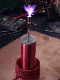
This pic shows the sparklength in nice-ish proportion to the coil... CW so no long streamers of course
ragnar, Wed Jul 12 2006, 10:20PM
Yes, copper is connected to the secondary base. :)
This pic shows the sparklength in nice-ish proportion to the coil... CW so no long streamers of course


Re: Class E SSTC thread
Marko, Wed Jul 12 2006, 10:50PM
I didn't actually do much work here last 2 days, as I was mostly cleaning my room
Also dug up some old interesting stuff.
I can't really have some serious frequency-tracking problems since PLL seems to work quite good.
class E amp actually doesn't like good coupling and impedance match, and what seems to be happening that circuit matches into impedance of unloaded coil better than it's impedance is 'increased' by breakout, considering that spark looks like a parallel resistor to resonator.
I'm not yet sure how can I calculate impedance for class E (wierd voltages/currents) wich also uses primary as inductor, but I'l rather go into 'experimental science than post my ramblings over here.
Reducing coupling would for example help but then I get small sparks. :p
I think I should reduce number of primary turns a bit, maybe some more leakage inductance and etc.
Too much posting crap and not enough work anyway.
Blackplasma: spark looks nice but still somewhat smaler than your first pic. (?)
Maybe you really should move the primary cm or two up from the ground plane, looks like you are making induction heater over there..
Marko, Wed Jul 12 2006, 10:50PM
Firkragg, if you have a good match when there is breakout, it is unlikely that there will be a match when there is no arc. With no breakout, your inductively coupled resonator is unloaded and will appear inductive (below resonance). Given the high-Q of the resonator, this corresponds to wide shifts in input impedance over small frequency excursions. Before breakout, you need to excite the coil with a frequency that is slightly higher than when it's running with an arc (plus...at startup, your driver must tolerate high voltages because of power reflected back from the unloaded resonator).. I believe the PLL-based systems try to track these frequency shifts on start-up and when the arc-loading conditions change.
I didn't actually do much work here last 2 days, as I was mostly cleaning my room

Also dug up some old interesting stuff.
I can't really have some serious frequency-tracking problems since PLL seems to work quite good.
class E amp actually doesn't like good coupling and impedance match, and what seems to be happening that circuit matches into impedance of unloaded coil better than it's impedance is 'increased' by breakout, considering that spark looks like a parallel resistor to resonator.
I'm not yet sure how can I calculate impedance for class E (wierd voltages/currents) wich also uses primary as inductor, but I'l rather go into 'experimental science than post my ramblings over here.
Reducing coupling would for example help but then I get small sparks. :p
I think I should reduce number of primary turns a bit, maybe some more leakage inductance and etc.
Too much posting crap and not enough work anyway.
Blackplasma: spark looks nice but still somewhat smaler than your first pic. (?)
Maybe you really should move the primary cm or two up from the ground plane, looks like you are making induction heater over there..

Re: Class E SSTC thread
ragnar, Thu Jul 13 2006, 11:39AM
Raising the primary increases the coupling a wee bit much making it hard to hold class-E critical damping on the shunt capacitor, but if he were also increased in diameter, then I could keep the coupling constant and move it away from the secondary... That'd also help with any flashover issues.
As for the pics (breakout into one plume, wire brush breakout, me at work, breakout into three plumes) ... meh, I couldn't help myself
Sorry 'bout the filesizes, guys =)
[edit]so I don't get into trouble, I've made the GIFs into links. Please, click them! :P[/edit]
animated GIF of breakout into a single plume
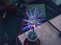
animated GIF of breakout into three plumes
ragnar, Thu Jul 13 2006, 11:39AM
Raising the primary increases the coupling a wee bit much making it hard to hold class-E critical damping on the shunt capacitor, but if he were also increased in diameter, then I could keep the coupling constant and move it away from the secondary... That'd also help with any flashover issues.
As for the pics (breakout into one plume, wire brush breakout, me at work, breakout into three plumes) ... meh, I couldn't help myself

Sorry 'bout the filesizes, guys =)
[edit]so I don't get into trouble, I've made the GIFs into links. Please, click them! :P[/edit]
animated GIF of breakout into a single plume

animated GIF of breakout into three plumes
Re: Class E SSTC thread
..., Thu Jul 13 2006, 02:38PM
good job BP
Have you put any though into audiomodulation? I seem to remember you trying to use a flyback for some singing plasma, but had problems... I bet that you could get a decent listening volume out of that coil, and beat evr to the first good audiomod coil The max038 does have a duty cycle input, doesn't it? Perhapse you can just use the detuning effect of the changing duty cycle to get the modulation...
The only things I get to make at work at 555 driven fets to run .25a pulses at 1khz through a coil of wire... I almost got to order some max038's to make a sign wave generator to feed a simple linear amp (pnp transistor) to get a sign wave through the coil, but they decided a square wave would be ok I am going to try to convince them to let me make my own power supply for it today
..., Thu Jul 13 2006, 02:38PM
good job BP

Have you put any though into audiomodulation? I seem to remember you trying to use a flyback for some singing plasma, but had problems... I bet that you could get a decent listening volume out of that coil, and beat evr to the first good audiomod coil
 The max038 does have a duty cycle input, doesn't it? Perhapse you can just use the detuning effect of the changing duty cycle to get the modulation...
 The only things I get to make at work at 555 driven fets to run .25a pulses at 1khz through a coil of wire... I almost got to order some max038's to make a sign wave generator to feed a simple linear amp (pnp transistor) to get a sign wave through the coil, but they decided a square wave would be ok
 I am going to try to convince them to let me make my own power supply for it today
Re: Class E SSTC thread
Marko, Thu Jul 13 2006, 04:15PM
I was actually wondering when is he going to test his high-Q acrylic litz-wire resonator.
With some topload and proper drive it could make some nice output.
I still don't understand what's he trying with that 2N7000 fet's altough..
*update - class E SSTC dies*
to be continued...
Marko, Thu Jul 13 2006, 04:15PM
I was actually wondering when is he going to test his high-Q acrylic litz-wire resonator.
With some topload and proper drive it could make some nice output.
I still don't understand what's he trying with that 2N7000 fet's altough..
*update - class E SSTC dies*

to be continued...
Re: Class E SSTC thread
ragnar, Fri Jul 14 2006, 01:20AM
Pwn3d.
ragnar, Fri Jul 14 2006, 01:20AM
Pwn3d.
Re: Class E SSTC thread
Tom540, Fri Jul 14 2006, 03:28AM
This is making me want to mess screw around a little too. I have a few extra secondaries also. One works at around 4MHz and the other 900KHz. It's too hot and im lazy though right now. I'm also gonna be moving in a few weeks so thats my other excuse until I get paid and get more parts.
Re: Class E SSTC thread
ragnar, Fri Jul 14 2006, 07:54AM
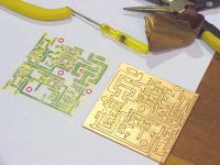
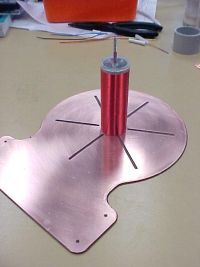
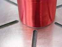
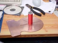
A tesla coil's no fun without an appropriately pretty base... so I whipped this up from some of my single-layer copper-clad (which I can't use for routing boards). =-D
ragnar, Fri Jul 14 2006, 07:54AM
A tesla coil's no fun without an appropriately pretty base... so I whipped this up from some of my single-layer copper-clad (which I can't use for routing boards). =-D


Re: Class E SSTC thread
Marko, Fri Jul 14 2006, 12:22PM
BP, I really don't see a reason why don't you build yourself a nice big DRSSTC, with all that copper clad, acrylic, tons of wire and tons of machines to work everything.

I also don't see why don't you like mains ground but I'l let you be.
There shouldn't be any problems if you raise secondary and primary for cm or two.
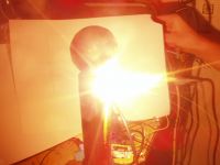
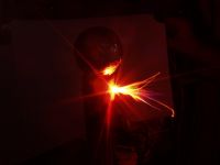
The problem with bad secondary contact on my SSTC appeared again - this time pressure released itself trough hole on side I used to pass wire in. I caught the first explosion on the pic (I was trying to photograph sparks).
After several failures I fixed it but I know this secondary won't last long after.
Explosion took out about 30 top turns so i'm operating on a bit higher frequency now..
I repeated the shot with just touching the supply, it can be clearly seen what was going on..
Marko, Fri Jul 14 2006, 12:22PM
BP, I really don't see a reason why don't you build yourself a nice big DRSSTC, with all that copper clad, acrylic, tons of wire and tons of machines to work everything.

I also don't see why don't you like mains ground but I'l let you be.
There shouldn't be any problems if you raise secondary and primary for cm or two.
The problem with bad secondary contact on my SSTC appeared again - this time pressure released itself trough hole on side I used to pass wire in. I caught the first explosion on the pic (I was trying to photograph sparks).
After several failures I fixed it but I know this secondary won't last long after.
Explosion took out about 30 top turns so i'm operating on a bit higher frequency now..

I repeated the shot with just touching the supply, it can be clearly seen what was going on..

Re: Class E SSTC thread
Steve Conner, Fri Jul 14 2006, 12:42PM
Stop being so immature.
BP, nice looking base plate, but I take it you cut those slots to avoid eddy current losses? In which case, they ought to go further in towards the centre, probably.
The 2N7000 thing was intended as an isolated gate driver AFAIK. But it takes a lot to beat the power of UCC3732x.
Steve Conner, Fri Jul 14 2006, 12:42PM
blackplasma wrote ...
Pwn3d.
Pwn3d.
Stop being so immature.

BP, nice looking base plate, but I take it you cut those slots to avoid eddy current losses? In which case, they ought to go further in towards the centre, probably.
The 2N7000 thing was intended as an isolated gate driver AFAIK. But it takes a lot to beat the power of UCC3732x.
Re: Class E SSTC thread
Marko, Fri Jul 14 2006, 01:17PM
But once you grow up, where is the fun
Gate drive really seems not to be so critical with class E. Richieburnett acheived good efficiency by just feeding sinewave to main mosfet's gate.
my and bp's designs are bit different since we are using the primary itself as a choke, and burnett coupled it separately to amplifier.
I don't know if there are benefits in it.
I still can't adjust primary tank circuit to work with unloaded coil. It still gets heavily overdamped. I guessed I need more capacitance but I don't have lots of adequate MKP caps.

Reason seems to be 'too good' impedance match without spark, and coil draws loots of power in this state.
When spark 'loads' it it changes Q and impedance of resonator making class E stage less loaded.
Sorry for writing crap =)
When this resonator dies I'l have either to use a reserve one or wind new, I think I'l want it to be a bit smaller this time, but keeping same resonant frequncy.
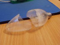
Coil emits pretty powerful electric field when there is no breakout.
I held this bulb about 10cm from the coil and it caused a storm of plasma inside.
Heating was so rapid and intense that bulb quivered and cracked in half in matter of seconds.
I guess high toplaod capacitance and very high frequency contributed that too.
Marko, Fri Jul 14 2006, 01:17PM
Stop being so immature.
But once you grow up, where is the fun

Gate drive really seems not to be so critical with class E. Richieburnett acheived good efficiency by just feeding sinewave to main mosfet's gate.
my and bp's designs are bit different since we are using the primary itself as a choke, and burnett coupled it separately to amplifier.
I don't know if there are benefits in it.
I still can't adjust primary tank circuit to work with unloaded coil. It still gets heavily overdamped. I guessed I need more capacitance but I don't have lots of adequate MKP caps.

Reason seems to be 'too good' impedance match without spark, and coil draws loots of power in this state.
When spark 'loads' it it changes Q and impedance of resonator making class E stage less loaded.
Sorry for writing crap =)
When this resonator dies I'l have either to use a reserve one or wind new, I think I'l want it to be a bit smaller this time, but keeping same resonant frequncy.
Coil emits pretty powerful electric field when there is no breakout.
I held this bulb about 10cm from the coil and it caused a storm of plasma inside.
Heating was so rapid and intense that bulb quivered and cracked in half in matter of seconds.
I guess high toplaod capacitance and very high frequency contributed that too.

Re: Class E SSTC thread
ragnar, Sat Jul 15 2006, 03:22AM
Hehe, nice try. Couple of problems -- DRSSTCs don't appeal to me as yet, considering I'm broke, juggling school, a day-job that doesn't pay, and my own commercial endeavours in what is an impossible timeframe. The only acrylic I get to use is offcuts. As for the wire, AUD$77 for 7kg of 0.15mm solder-through enamelled copper means I'll never have to buy wire again. I only build small coils, anyway.
It's just the frequency that irks me about the mains ground vs return currents, and also the thought that "if I don't actually needa mains ground for this to run satisfactorily, why bother?" -- it tends to introduce noise to e.g. radios on the same circuit.
Any ideas on how I might make the baseplate and/or enclosure for the electronics look a whole lot better? =P
ragnar, Sat Jul 15 2006, 03:22AM
wrote ...
BP, I really don't see a reason why don't you build yourself a nice big DRSSTC, with all that copper clad, acrylic, tons of wire and tons of machines to work everything.
BP, I really don't see a reason why don't you build yourself a nice big DRSSTC, with all that copper clad, acrylic, tons of wire and tons of machines to work everything.
Hehe, nice try. Couple of problems -- DRSSTCs don't appeal to me as yet, considering I'm broke, juggling school, a day-job that doesn't pay, and my own commercial endeavours in what is an impossible timeframe. The only acrylic I get to use is offcuts. As for the wire, AUD$77 for 7kg of 0.15mm solder-through enamelled copper means I'll never have to buy wire again. I only build small coils, anyway.
wrote ...
I also don't see why don't you like mains ground but I'l let you be.
There shouldn't be any problems if you raise secondary and primary for cm or two.
I also don't see why don't you like mains ground but I'l let you be.
There shouldn't be any problems if you raise secondary and primary for cm or two.
It's just the frequency that irks me about the mains ground vs return currents, and also the thought that "if I don't actually needa mains ground for this to run satisfactorily, why bother?" -- it tends to introduce noise to e.g. radios on the same circuit.
Any ideas on how I might make the baseplate and/or enclosure for the electronics look a whole lot better? =P
Re: Class E SSTC thread
..., Sat Jul 15 2006, 04:58AM
I would paint the copperless places black, then spray it all with a red clearcoat
Putting a nice black painted board (perhapse add a few red or blue/purple stripes if you are in the mood) with the normal colored components for contrast might look cool.
Then add the red primary on a clear or black acrylic former... And some sparks on top
But that is just me...
..., Sat Jul 15 2006, 04:58AM
I would paint the copperless places black, then spray it all with a red clearcoat

Putting a nice black painted board (perhapse add a few red or blue/purple stripes if you are in the mood) with the normal colored components for contrast might look cool.
Then add the red primary on a clear or black acrylic former... And some sparks on top

But that is just me...
Re: Class E SSTC thread
Steve Conner, Sat Jul 15 2006, 06:45PM
Gate drive is much easier if you use a resonant drive circuit that puts out a sinewave like Richie did. I believe BP is using resonant gate drive now since he replaced the gate resistor with an inductor. The only danger is getting so much drive voltage through resonant rise that you blow up the MOSFET.
I don't think there is any drawback to using the primary itself as a choke like you're doing. Richie probably never thought of it. I think he was just thinking of commercial RF power amps. They need a separate DC bias path because they have to give an output from a socket to drive whatever load you plug in. The only thing you must remember is to put an RF bypass capacitor from the "Cold" end of the primary (the end connected to the DC supply) back to the place where the MOSFET source pin and Class-E snubber cap join. This completes the RF circuit and stops your power supply wiring being part of it.
I think it'll be impossible to match to an unloaded coil, since it's practically all reactive with hardly any actual real resistance. The resistance is what you're trying to match.
BP: Build a small DRSSTC then.
Steve Conner, Sat Jul 15 2006, 06:45PM
wrote ...
But once you grow up, where is the fun
Meh, I'm practically middle-aged, have a mortgage, and I'm still having fun. I heard the fun really stops when you have kids. >.<But once you grow up, where is the fun
Gate drive is much easier if you use a resonant drive circuit that puts out a sinewave like Richie did. I believe BP is using resonant gate drive now since he replaced the gate resistor with an inductor. The only danger is getting so much drive voltage through resonant rise that you blow up the MOSFET.
I don't think there is any drawback to using the primary itself as a choke like you're doing. Richie probably never thought of it. I think he was just thinking of commercial RF power amps. They need a separate DC bias path because they have to give an output from a socket to drive whatever load you plug in. The only thing you must remember is to put an RF bypass capacitor from the "Cold" end of the primary (the end connected to the DC supply) back to the place where the MOSFET source pin and Class-E snubber cap join. This completes the RF circuit and stops your power supply wiring being part of it.
I think it'll be impossible to match to an unloaded coil, since it's practically all reactive with hardly any actual real resistance. The resistance is what you're trying to match.
BP: Build a small DRSSTC then.

Re: Class E SSTC thread
Marko, Sat Jul 15 2006, 10:12PM
After I put the coil in faraday cage waveform repaired and the coil drew much less power, same as with breakout.
I blew my last IRFP450 having only 150's left, and input voltage is limited to some 30V, but I can still observe all the effects happening.
I tried to compesate this loading with bigger cap (22nF 100V from old fluke insrument, unknown construction) and less primary turns but that was the point where I blew the mosfet up
Could be tons of reasons, but anyway it's interesting to work on toploaded class-E coils
I'l keep you informed, now some more spark pics with various topload-toppings..
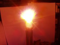
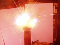
Marko, Sat Jul 15 2006, 10:12PM
After I put the coil in faraday cage waveform repaired and the coil drew much less power, same as with breakout.
I blew my last IRFP450 having only 150's left, and input voltage is limited to some 30V, but I can still observe all the effects happening.
I tried to compesate this loading with bigger cap (22nF 100V from old fluke insrument, unknown construction) and less primary turns but that was the point where I blew the mosfet up

Could be tons of reasons, but anyway it's interesting to work on toploaded class-E coils

I'l keep you informed, now some more spark pics with various topload-toppings..


Re: Class E SSTC thread
ragnar, Sat Jul 15 2006, 11:08PM
Some shorter exposures or videos would be nice =)
ragnar, Sat Jul 15 2006, 11:08PM
Some shorter exposures or videos would be nice =)
Re: Class E SSTC thread
Marko, Sun Jul 16 2006, 01:39PM
The first is done by putting some cotton on the topload. Arcs ignite it and streamers emanate from tips of the flame.
Even at short exposure (200ms) and lowered ISO it dazzled my camera. I didn't try this again as carbon was ruining my topload.
Second pic is steel wool, wittingly taken using 8 second exposure for sparkles a la Richie Burnett style
I also finally had some sucess with bigger (22nF) cap but some 15nF would be more preferable
I'm using 2 primary turns now and I minimised all inductances, but frequency of the LC still seems to be edgy low. May prove good for compensation of big streamers and loading..
PS.
I added a modulator to the coil, modulating inhibit pin of '4046. It worked nicely, lowered power draw but didn't help much making longer sparks.
Interesting is that at higher powers coil breaks out from topload on 'multiple places' like a small SGTC would do.
One bizzare thing I discovered is some dim 'modulation' of interrupter signal at about 2Hz.
It can be easily heard from a small streamers and from mains transformer.
I'm completly unsure what causes it another 'mystery' from this coil.
Marko, Sun Jul 16 2006, 01:39PM
The first is done by putting some cotton on the topload. Arcs ignite it and streamers emanate from tips of the flame.
Even at short exposure (200ms) and lowered ISO it dazzled my camera. I didn't try this again as carbon was ruining my topload.
Second pic is steel wool, wittingly taken using 8 second exposure for sparkles a la Richie Burnett style

I also finally had some sucess with bigger (22nF) cap but some 15nF would be more preferable

I'm using 2 primary turns now and I minimised all inductances, but frequency of the LC still seems to be edgy low. May prove good for compensation of big streamers and loading..
PS.
I added a modulator to the coil, modulating inhibit pin of '4046. It worked nicely, lowered power draw but didn't help much making longer sparks.
Interesting is that at higher powers coil breaks out from topload on 'multiple places' like a small SGTC would do.
One bizzare thing I discovered is some dim 'modulation' of interrupter signal at about 2Hz.
It can be easily heard from a small streamers and from mains transformer.
I'm completly unsure what causes it another 'mystery' from this coil.
Re: Class E SSTC thread
ragnar, Sun Jul 16 2006, 01:49PM
Got waveforms and circuit pics? :P
</hassle, hassle>
ragnar, Sun Jul 16 2006, 01:49PM
Got waveforms and circuit pics? :P
</hassle, hassle>
Re: Class E SSTC thread
Marko, Thu Jul 20 2006, 08:07PM
 This coil is really endless source of trouble, and I can never tune it for best output without ruining class E operation.
With new 15nF MKP cap(s) mosfet runs even hotter than before. I tried 2,3 and 4 turns with varying capacitance but I still did nothing good.
Top winding of my secondary is still burning out, causing trouble with measuring and I'l probablly never fully fix that.
Now I tried to shoot some waveforms but they tend to oscillate with variation of load due to spark, 50Hz ripple, arcing connections inside the resonator and massive heating of mosfet and it's surroundings :p
But it does resemble class E operation in somewhat.
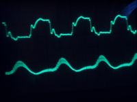
more pics
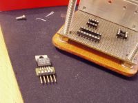
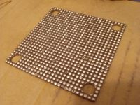
I coated the board with solder to prevent rusting of copper. Regulator will be in buck-boost mode to provide power to all the electronics regardless of input voltage.
I get a opposite polarity output but I don't thnk it's a big deal, since unregulated input won't appear in the circuit anyway.
Marko, Thu Jul 20 2006, 08:07PM
 This coil is really endless source of trouble, and I can never tune it for best output without ruining class E operation.
With new 15nF MKP cap(s) mosfet runs even hotter than before. I tried 2,3 and 4 turns with varying capacitance but I still did nothing good.
Top winding of my secondary is still burning out, causing trouble with measuring and I'l probablly never fully fix that.
Now I tried to shoot some waveforms but they tend to oscillate with variation of load due to spark, 50Hz ripple, arcing connections inside the resonator and massive heating of mosfet and it's surroundings :p
But it does resemble class E operation in somewhat.

more pics


I coated the board with solder to prevent rusting of copper. Regulator will be in buck-boost mode to provide power to all the electronics regardless of input voltage.
I get a opposite polarity output but I don't thnk it's a big deal, since unregulated input won't appear in the circuit anyway.
Re: Class E SSTC thread
ragnar, Sun Jul 23 2006, 01:34PM
Just posting my latest pics here -- these are from a different (nicer) camera, and are crisper and (I find) a truer description of the coil and discharge.
The last few pics are a premature announcement of first light of my UOMFGSTFUHFSSTC which runs at 9.5MHz.
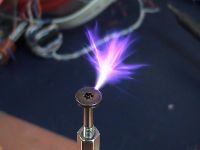
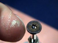
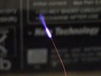
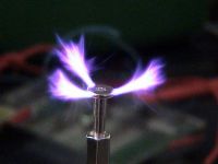
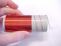
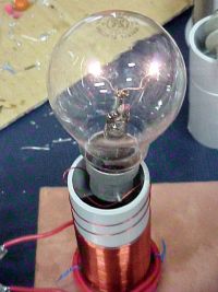
ragnar, Sun Jul 23 2006, 01:34PM
Just posting my latest pics here -- these are from a different (nicer) camera, and are crisper and (I find) a truer description of the coil and discharge.
The last few pics are a premature announcement of first light of my UOMFGSTFUHFSSTC which runs at 9.5MHz.


Re: Class E SSTC thread
Marko, Sun Jul 23 2006, 01:59PM
You can put pics in rows to save some space, looks neater =)
9,5Mhz is nice but I doubt you'l beat some spark recods with that :/
I think you can improve Q and sparks by using uber thick or multifilat wire, the acrylic secondary you had would be great.
And try not to fry yourself with that thing :p
Re: Class E SSTC thread
ragnar, Sun Jul 23 2006, 03:08PM
U stands for uber.
ragnar, Sun Jul 23 2006, 03:08PM
U stands for uber.
Re: Class E SSTC thread
..., Sun Jul 23 2006, 05:17PM
Any thoughts of putting that uber 1337 anticoil resonator on your Uber Oh My F***ing God Shut The F*** Up High Frequiency Tesla Coil Or could it the the Uooh Ouch My Finger Got Struck by The Flaming Uber High Frequiency Tesla Coil
..., Sun Jul 23 2006, 05:17PM
Any thoughts of putting that uber 1337 anticoil resonator on your Uber Oh My F***ing God Shut The F*** Up High Frequiency Tesla Coil
 Or could it the the Uooh Ouch My Finger Got Struck by The Flaming Uber High Frequiency Tesla Coil
Re: Class E SSTC thread
ragnar, Mon Jul 24 2006, 10:40AM
The power going through the anticoil would be disproportionate (to its size) considering the small amount of power I can currently monger with any of my drivers.
On the other hand, for extra geek points I'm raising the fres on the UOMFGSTFUHFSSTC to 12MHz and redesigning the driver starting tomorrow. When he comes to real fruition (as opposed to single-figure-wattage discharges in a lightbulb), I'll start a thread.
And yes, the name is immature, and you guys better choose something else for it. =)
Re: Class E SSTC thread
Marko, Mon Jul 24 2006, 01:07PM
I was a bit busy this days so assembly of main board turned a bit slowish. :/
Here is a simplified plan of entire coil (pic = 1000 words).
Just to add, electronics are supplied from polarity inverse to input voltage due to buck/boost.
LM2575 shuts the circuit down once heatsink reaches critical temperature.
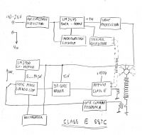

Re: Class E SSTC thread
Steve Conner, Tue Jul 25 2006, 01:11PM
If your regulator is giving a negative output, you're going to have trouble driving the gate of the main FET directly, since it needs a positive voltage. Put a minus sign in front of the "15V" label on your "9A Gate Driver" block and think about what's going to happen.
Re: Class E SSTC thread
Marko, Tue Jul 25 2006, 05:19PM
Yeah, I see now.
Schematic is a bit wrong, since I should have put 'GND's on anywhere -15V goes, and actual GND is Vcc to chps.
-15V also goes to source of mosfet wich isn't actually shown.
Since I'm not using initial unregulated supply anywhere directly there's no actual need to correct polarity towards it.
Re: Class E SSTC thread
Steve Conner, Tue Jul 25 2006, 11:00PM
Ohh, I thought you were driving the logic off the same battery or whatever, as the drain supply to the Class-E power amp. My mistake. If you're not doing that though, why do you need the fancy buck-boost regulator at all? Can't you just use an auxiliary supply that gives more voltage?
BTW, I got this from Richie Burnett, I guess he's been reading our ponderings on what the RF chokes are for. Thanks Richie! :P
I guess the practical upshot of this, is that if you decide to use your primary coil in place of the RFC, you should bring the other end of the primary coil (that isn't connected to the drain) back close to the MOSFET source terminal, and connect it to the source via the best RF bypass capacitor you can get, making sure it has short leads. Then feed in the DC power across this cap. Even so, it'll probably still barf more RF back into the power supply wires than if you did it Richie's way.
Steve Conner, Tue Jul 25 2006, 11:00PM
Ohh, I thought you were driving the logic off the same battery or whatever, as the drain supply to the Class-E power amp. My mistake. If you're not doing that though, why do you need the fancy buck-boost regulator at all? Can't you just use an auxiliary supply that gives more voltage?
BTW, I got this from Richie Burnett, I guess he's been reading our ponderings on what the RF chokes are for. Thanks Richie! :P
richie wrote ...
Incidentally, the reason why you should use an RFC, normally in the drain
lead of a Class-E amp is because it acts like a constant current source and
presents a high impedance to all the harmonics from the MOSFET switching.
In short, it keeps RF current out of the supply wiring. In a Class E SSTC
you could connect the TC primary in place of the RFC and it does work, but
its inductance value will be much smaller than the RFC that you would
otherwise have used to supply the drain. This means that there will be a
larger ripple current through this component acting as the drain choke, plus
the actual AC load current which flows through this inductor and the supply
wiring!
The drain choke is normally thought of as a constant supply of current
because it is sized to be large compared to the operating frequency. Since
it is large the current through the RFC doesn't change significantly during
one RF cycle. This constant current is then alternately redirected between
the MOSFET channel and the load network of the Class-E amp as the device
switches. In the interest of not quickly re-directing large currents over
large paths, it makes sense to connect the load network of the Class-E
amplifier directly across the switch. I.e. Drain-to-source across the
MOSFET. Then the choke current can alternate between the MOSFET channel and
the load network without having to take a detour around the PSU wiring and
decoupling!
I guess the practical upshot of this, is that if you decide to use your primary coil in place of the RFC, you should bring the other end of the primary coil (that isn't connected to the drain) back close to the MOSFET source terminal, and connect it to the source via the best RF bypass capacitor you can get, making sure it has short leads. Then feed in the DC power across this cap. Even so, it'll probably still barf more RF back into the power supply wires than if you did it Richie's way.
Re: Class E SSTC thread
Marko, Sun Sept 10 2006, 06:28PM
Oh, thanks steve! I will be putting a large dewcoupling cap and biggest filter choke I can find on 100V bus!
I already noticed that I can draw 'arcs' from my power supply (~50V) when I disconnect the aligator clip.
RF sloshed back into power supply ignites a small arc and onised air conducts amp-tow of current while clip is few mm open!
A bit forgotten project I admit But beginning of school somehow gave my will back.
Last days I have been testing the board I built, designed to fit beautifully in small box I had.
Marko, Sun Sept 10 2006, 06:28PM
Oh, thanks steve! I will be putting a large dewcoupling cap and biggest filter choke I can find on 100V bus!
I already noticed that I can draw 'arcs' from my power supply (~50V) when I disconnect the aligator clip.
RF sloshed back into power supply ignites a small arc and onised air conducts amp-tow of current while clip is few mm open!
A bit forgotten project I admit
 But beginning of school somehow gave my will back.
Last days I have been testing the board I built, designed to fit beautifully in small box I had.
Re: Class E SSTC thread
Marko, Sun Sept 17 2006, 04:06PM
The thing is fully functional finally.
Board is ready to fit into it's place..
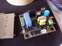
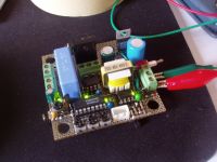
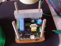
Driving a IRFP450 (2,5nF) at 2Mhz, gate signal 500ns 5V div. I took special care for a low inductance design and I get almost datasheet-like rise and fall times with 1 ohm gate resistor. UCC gets pretty hot with this. SMD resistor does good job keeping inductance low..
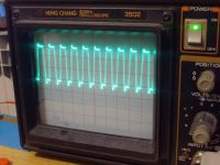
Under-board.
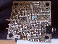
And yeah, I didn't forget to make space for power supply..
FOr higher power levels I may add forced air cooling to small heatsink..
Marko, Sun Sept 17 2006, 04:06PM
The thing is fully functional finally.
Board is ready to fit into it's place..


Driving a IRFP450 (2,5nF) at 2Mhz, gate signal 500ns 5V div. I took special care for a low inductance design and I get almost datasheet-like rise and fall times with 1 ohm gate resistor. UCC gets pretty hot with this. SMD resistor does good job keeping inductance low..


Under-board.

And yeah, I didn't forget to make space for power supply..
FOr higher power levels I may add forced air cooling to small heatsink..
Re: Class E SSTC thread
EDY19, Sun Sept 17 2006, 06:04PM
That looks VERY nice, firkragg! The gate waveforms are also quite impressive. Have any tests with a coil in place been done with this setup?
EDY19, Sun Sept 17 2006, 06:04PM
That looks VERY nice, firkragg! The gate waveforms are also quite impressive. Have any tests with a coil in place been done with this setup?
Re: Class E SSTC thread
Marko, Tue Sept 19 2006, 10:09PM
I assembled the coil and did some preliminary tests; 2cm sparks at 12V, nothing impressive, and PLL seems to be somehow unlocky. I think I really need bigger VCO cap and a bit bigger
DC blocking cap at CT, I think it is being overloaded and CT current is very low at low input voltages.
I know spark looks awful, I have always had trouble with that. I would need to shoot in dark and focus poorly on the rest of coil :/ If I underexpose sparks look few times shorter than really.
This run is at about 20V, som 4cm sparks.
I didn't check it for class E yet but I used the same cap from before, primary and coupling are also close enough.
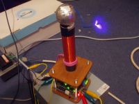

Re: Class E SSTC thread
Marko, Tue Oct 10 2006, 09:49PM
Coil got a new secondary and fancy hovering primary; I'm currently happy with it as is.
Power supply will be added but I don't want to press with it.
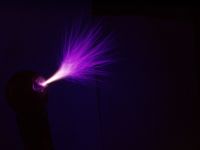
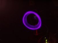
This is how I blew my old secondary: after playng with various spark effects, vortexes and trans-dimensional portals I finally tangled a wire just in the middle of the secondary, shorting a lot of turns and setitng the thing of fire.
As he was ruin anyway I decided to make a new one, and this time without bad connections and bugs. With nicer, bigger topload it works flawlessly, somewhere above 1Mhz.
I don't aim for extreme frequencies yet as people still find large sparks more amusing than fact that coil works at 30Mhz or etc.
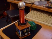
Marko, Tue Oct 10 2006, 09:49PM
Coil got a new secondary and fancy hovering primary; I'm currently happy with it as is.
Power supply will be added but I don't want to press with it.


This is how I blew my old secondary: after playng with various spark effects, vortexes and trans-dimensional portals I finally tangled a wire just in the middle of the secondary, shorting a lot of turns and setitng the thing of fire.
As he was ruin anyway I decided to make a new one, and this time without bad connections and bugs. With nicer, bigger topload it works flawlessly, somewhere above 1Mhz.
I don't aim for extreme frequencies yet as people still find large sparks more amusing than fact that coil works at 30Mhz or etc.


Re: Class E SSTC thread
..., Tue Oct 10 2006, 10:15PM
wow!
Any thought about building (or buying, but there in no fun in that) a little smps supply to power it off a battery and building a level below the main driver electronics? I coil is no fun if you have to hook it up to like 5 power supplies to make it run
..., Tue Oct 10 2006, 10:15PM
wow!
Any thought about building (or buying, but there in no fun in that) a little smps supply to power it off a battery and building a level below the main driver electronics? I coil is no fun if you have to hook it up to like 5 power supplies to make it run

Re: Class E SSTC thread
Marko, Tue Oct 10 2006, 10:34PM
Hah, don't need to believe me, but I left space for SMPS *inside* the coil.
Once I put it in I will be able to power entire thing from 10..25V and have any voltage I want at class E amp.
Maybe even audiomodulate the supply, although current PLL works relatively fine at low power.
Re: Class E SSTC thread
Coronafix, Wed Oct 11 2006, 03:15AM
Neat little coil!!
How did you get that vortex effect?
It looks great!
Coronafix, Wed Oct 11 2006, 03:15AM
Neat little coil!!
How did you get that vortex effect?
It looks great!
Re: Class E SSTC thread
ragnar, Wed Oct 11 2006, 03:43AM
Vortex is achieved by pulling off the top turn of the secondary, and letting the ions blast it around in a circle. Looks very pretty and sounds quite fascinating if you ever get to see it for real =-D
ragnar, Wed Oct 11 2006, 03:43AM
Vortex is achieved by pulling off the top turn of the secondary, and letting the ions blast it around in a circle. Looks very pretty and sounds quite fascinating if you ever get to see it for real =-D
Print this page
