
High voltage probe for O-scope, 2 of 2, ( FABRICATION ).
Patrick, Mon Sept 26 2011, 08:34AMThis thread will be dedicated to the fabrication and operation of the final probe design. Any replies should be with that understanding of intent and the normal project thread rules. All other comments, criticism and suggestions should be made to this thread:
 High Voltage probe for O-scope, 1 of 2, ( DEVELOPMENT ).
(Compensation circuits have been posted on the "Development" thread.)
Otherwise Please comment!
Background info:
Sam Goldwasser's HV probe page...

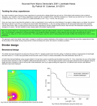
Marco Denicolai's explanation of his 20 liter water HV probe (600kV).
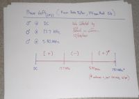
[Note what i have highlighted in green.]
His PDF is here:
Marco's tesla and thesis site:

Background Info End.
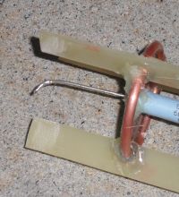
These next few pics show the construction of what i call the "High Voltage RC Element", this device is a SSX39 MG resistor,
125 Mohms in parallel with a coaxial 4.9-5.2 pF oil capacitor, both are meant to withstand 14 kV. 3 of these "elements" will be in series to obtain a 42 kV probe of 375 Mohms, at 1.5 to 1.7 pF. I just pray the field distrubution and capacitence is enough, the Northstars have 10 pF for a similar spec'ed probe. The bottom most plate is insulated from the resistor body, as the voltage drop beneath it is 800 volts less then the plate. This probe will be food oil filled and have a 10,000:1 division ratio.

Sheet metal and copper ring.
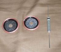
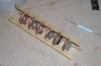
Plates of steel and copper soldered and epoxied, then attatched as per the FEMM model for field distrubution.
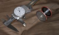
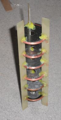
Temporary hot glue mock up to test fit and funtion, this will be redone in oil proof epoxy soon.
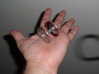
A single HV RC element seen here in my hand.
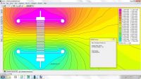
The resistor's V drop is linearized with the cap plates, and grading rings.

Zoey, best dog ever, on quality control.
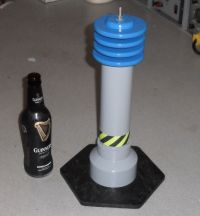
Insulator is acrylic should be good for 50kV+
****************************************** *****
[Gen 5, Type 3, Mod 6, Rev J, Ver 3.0, Attempt 12]
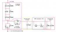
Final schematic, as it will be built in the next 7-10 days.

C5 should be variable from 294 pF to 319pF, which will allow an oscope with 7-30pF internal capacity to be compensated.
The Ross Engineering, NorthStars, and the patent, as well as my probe all have one adjustment, to calibrate/compensate. This is a significant advantage over the 5 or more pots and trimmers the Tek p601(3,4,5)'s had.
******************************************** ************
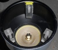
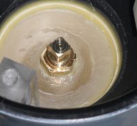
Oil Drain, and bottom end of the HV section.
More to come soon!
Re: High voltage probe for O-scope, 2 of 2, ( FABRICATION ).
Patrick, Sat Oct 01 2011, 05:16PM
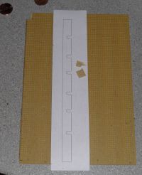
I used this cheap circuit predrilled stuff but it was so weak, while making the piece i needed, it broke apart in my fingers. Ill need to use the real FR4 circuit board stuff then, its hard to cut though.
Patrick, Sat Oct 01 2011, 05:16PM
I used this cheap circuit predrilled stuff but it was so weak, while making the piece i needed, it broke apart in my fingers. Ill need to use the real FR4 circuit board stuff then, its hard to cut though.

Re: High voltage probe for O-scope, 2 of 2, ( FABRICATION ).
Patrick, Tue Oct 04 2011, 06:40AM
[Gen 5, Type 3, Mod 60, Rev J, Ver 3.0, Attempt 12]
Final schematic, as it will be built in the next 7-10 days.

C5 should be variable from 294 pF to 319pF, which will allow an oscope with 7-30pF internal capacity to be compensated.
The Ross Engineering, NorthStars, and the patent, as well as my probe all have one adjustment, to calibrate/compensate. This is a significant advantage over the 5 or more pots and trimmers the Tek p601(3,4,5)'s had.
Patrick, Tue Oct 04 2011, 06:40AM
[Gen 5, Type 3, Mod 60, Rev J, Ver 3.0, Attempt 12]
Final schematic, as it will be built in the next 7-10 days.

C5 should be variable from 294 pF to 319pF, which will allow an oscope with 7-30pF internal capacity to be compensated.
The Ross Engineering, NorthStars, and the patent, as well as my probe all have one adjustment, to calibrate/compensate. This is a significant advantage over the 5 or more pots and trimmers the Tek p601(3,4,5)'s had.
Re: High voltage probe for O-scope, 2 of 2, ( FABRICATION ).
Mattski, Tue Oct 04 2011, 03:57PM
Is that 50 Ohm resistor actually part of the BNC connector? I would expect the connector to just have some stray capacitance and no resistance.
Mattski, Tue Oct 04 2011, 03:57PM
Is that 50 Ohm resistor actually part of the BNC connector? I would expect the connector to just have some stray capacitance and no resistance.
Re: High voltage probe for O-scope, 2 of 2, ( FABRICATION ).
Patrick, Tue Oct 04 2011, 04:10PM
When I add it, it will probably be a tube/bulge cover by heatshrink tubing.
Patrick, Tue Oct 04 2011, 04:10PM
Mattski wrote ...
Is that 50 Ohm resistor actually part of the BNC connector? I would expect the connector to just have some stray capacitance and no resistance.
Im going to add the resistor and capacitor, very close the the BNC connector, the connector is just the common straight through type. Is that 50 Ohm resistor actually part of the BNC connector? I would expect the connector to just have some stray capacitance and no resistance.
When I add it, it will probably be a tube/bulge cover by heatshrink tubing.
Re: High voltage probe for O-scope, 2 of 2, ( FABRICATION ).
Mattski, Tue Oct 04 2011, 04:19PM
Ah I see, I had thought that you were modeling the effects of the connector as a resistor and capacitor.
Mattski, Tue Oct 04 2011, 04:19PM
Ah I see, I had thought that you were modeling the effects of the connector as a resistor and capacitor.
Re: High voltage probe for O-scope, 2 of 2, ( FABRICATION ).
Patrick, Tue Oct 04 2011, 04:49PM

I also want to make a 1 or 3 kV square wave calibrator at 1-10 kHz.
EDIT new work :

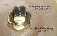
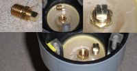
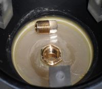
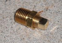
Oil drain.
Patrick, Tue Oct 04 2011, 04:49PM
Mattski wrote ...
Ah I see, I had thought that you were modeling the effects of the connector as a resistor and capacitor.
Nope. Ah I see, I had thought that you were modeling the effects of the connector as a resistor and capacitor.

I also want to make a 1 or 3 kV square wave calibrator at 1-10 kHz.
EDIT new work :

Oil drain.
Re: High voltage probe for O-scope, 2 of 2, ( FABRICATION ).
Patrick, Thu Oct 13 2011, 12:51AM
New method for removing the silicone conformal coating from the caps, using MEK.

cap plates will be added shortly.
Patrick, Thu Oct 13 2011, 12:51AM
New method for removing the silicone conformal coating from the caps, using MEK.

cap plates will be added shortly.
Re: High voltage probe for O-scope, 2 of 2, ( FABRICATION ).
Sulaiman, Thu Oct 13 2011, 04:05PM
Patrick,
" I also want to make a 1 or 3 kV square wave calibrator at 1-10 kHz."
How will you calibrate the calibrator?
Sulaiman, Thu Oct 13 2011, 04:05PM
Patrick,
" I also want to make a 1 or 3 kV square wave calibrator at 1-10 kHz."
How will you calibrate the calibrator?
Re: High voltage probe for O-scope, 2 of 2, ( FABRICATION ).
Patrick, Thu Oct 13 2011, 07:03PM
It only needs to have a high rise and fall time. IE, a square wave, like what is on the front of the oscilloscopes for compensation. (and serving the same purpose.)
The Tek, northstars, ross engineering and mine have pretty high accuracy from DC to 100Hz (like 0.1%) , yet the accuracy worsens towards 50MHz (like 3-5%).
Thus my HF probe and the others (except the tek P60** series) only need a single compensation screw.
The tek P6015 has 900 pots and trimmers right? turn this one a weee bit this way, the next a weee bit the other way.... then do it again, and again, and again.
Patrick, Thu Oct 13 2011, 07:03PM
Sulaiman wrote ...
Patrick,
" I also want to make a 1 or 3 kV square wave calibrator at 1-10 kHz."
How will you calibrate the calibrator?
Patrick,
" I also want to make a 1 or 3 kV square wave calibrator at 1-10 kHz."
How will you calibrate the calibrator?
It only needs to have a high rise and fall time. IE, a square wave, like what is on the front of the oscilloscopes for compensation. (and serving the same purpose.)
The Tek, northstars, ross engineering and mine have pretty high accuracy from DC to 100Hz (like 0.1%) , yet the accuracy worsens towards 50MHz (like 3-5%).
Thus my HF probe and the others (except the tek P60** series) only need a single compensation screw.
The tek P6015 has 900 pots and trimmers right? turn this one a weee bit this way, the next a weee bit the other way.... then do it again, and again, and again.
Re: High voltage probe for O-scope, 2 of 2, ( FABRICATION ).
Patrick, Thu Oct 13 2011, 08:10PM
Im getting 2.4 pF, 2.4 pF, 1.4 pF. all three should be in the 2.4 range dam it , i dont know what im going to do if this build comes out wrong.
Im checking my measurements now.
Ok when i measure it vertically it seems to be 1.5 pF for all three, still checking though.
Re: High voltage probe for O-scope, 2 of 2, ( FABRICATION ).
Pinky's Brain, Thu Oct 13 2011, 09:43PM
Easier said than done for more than 1 kV, transformer won't be sharp and a single MOSFET on each leg of a bridge won't get you there.
Pinky's Brain, Thu Oct 13 2011, 09:43PM
Easier said than done for more than 1 kV, transformer won't be sharp and a single MOSFET on each leg of a bridge won't get you there.
Re: High voltage probe for O-scope, 2 of 2, ( FABRICATION ).
Patrick, Thu Oct 13 2011, 11:41PM
Wait, wait, wait i have a great idea!
What about this, TVS diodes were used with a ramping voltage up to breakover? I have to think about this more.
Patrick, Thu Oct 13 2011, 11:41PM
Pinky's Brain wrote ...
Easier said than done for more than 1 kV, transformer won't be sharp and a single MOSFET on each leg of a bridge won't get you there.
If you mean for the square wave generator, i was planning to use two 1 kV MOSFETs in series, switching a resistor on and off at 2kV, but i dont know how to do so with out killing the MOSFETs .Easier said than done for more than 1 kV, transformer won't be sharp and a single MOSFET on each leg of a bridge won't get you there.
Wait, wait, wait i have a great idea!
What about this, TVS diodes were used with a ramping voltage up to breakover? I have to think about this more.
Re: High voltage probe for O-scope, 2 of 2, ( FABRICATION ).
Pinky's Brain, Fri Oct 14 2011, 03:11PM
If all you are ever going to do with the generator is switching into into your divider (essentially a xx pF load) the TVSs can almost certainly handle it even if a gate drive were too fail ... it's just not a whole lot of power.
If it has to be able to deliver some real power to a lower impedance load you will have to be a bit more careful.
Re: High voltage probe for O-scope, 2 of 2, ( FABRICATION ).
Patrick, Fri Oct 14 2011, 04:42PM
Ive got the whole HV section assembled after class ill fill it with olive oil.
A disturbing developement: its top heavy, dam it. And thats without oil and just the acrylic insulator. with the porcilain insulator it'll be even more so.
Patrick, Fri Oct 14 2011, 04:42PM
Ive got the whole HV section assembled after class ill fill it with olive oil.
A disturbing developement: its top heavy, dam it. And thats without oil and just the acrylic insulator. with the porcilain insulator it'll be even more so.
Re: High voltage probe for O-scope, 2 of 2, ( FABRICATION ).
Pinky's Brain, Fri Oct 14 2011, 06:03PM
Oops, I have been messing up board rules ... if any mod comes by can you move my posts :/
Pinky's Brain, Fri Oct 14 2011, 06:03PM
Oops, I have been messing up board rules ... if any mod comes by can you move my posts :/
Re: High voltage probe for O-scope, 2 of 2, ( FABRICATION ).
Patrick, Sat Oct 15 2011, 06:10AM
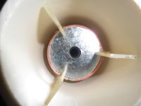
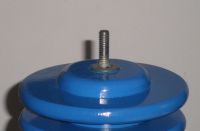
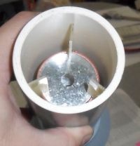
More neW work and pics (Whoa, im toTally drunk right now)
...
Which is better for corona reduction? A or B
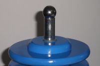
A
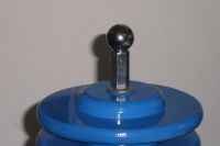
B
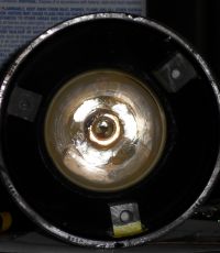
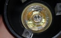

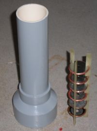
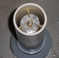
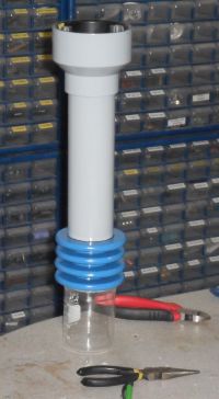
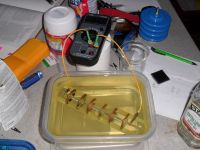
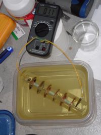
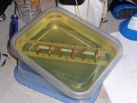

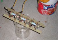

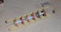
pics

pics
pics
[
pics
pics
Patrick, Sat Oct 15 2011, 06:10AM
More neW work and pics (Whoa, im toTally drunk right now)
...
Which is better for corona reduction? A or B

A

B


pics


pics

pics


[
pics


pics


Re: High voltage probe for O-scope, 2 of 2, ( FABRICATION ).
Patrick, Sun Oct 16 2011, 06:27AM
Finalized schematic...
Patrick, Sun Oct 16 2011, 06:27AM
Finalized schematic...

Re: High voltage probe for O-scope, 2 of 2, ( FABRICATION ).
Patrick, Wed Oct 19 2011, 04:24AM
It tested good with DC and low freq AC, 6kV RMS. LV caps are due in tomorrow.
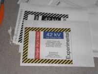
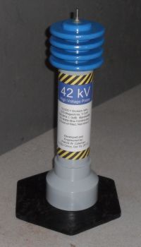
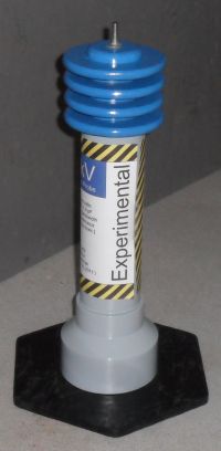
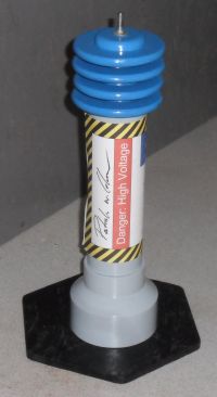
New work: 10/19/2011, Proof labels...
Patrick, Wed Oct 19 2011, 04:24AM
It tested good with DC and low freq AC, 6kV RMS. LV caps are due in tomorrow.
New work: 10/19/2011, Proof labels...


Re: High voltage probe for O-scope, 2 of 2, ( FABRICATION ).
Patrick, Thu Oct 20 2011, 04:35AM
All parts arrived today, ill etch a board and put things together tomorrow...
Patrick, Thu Oct 20 2011, 04:35AM
All parts arrived today, ill etch a board and put things together tomorrow...
Re: High voltage probe for O-scope, 2 of 2, ( FABRICATION ).
Patrick, Mon Oct 31 2011, 12:05AM
New work from 10/30/2011:
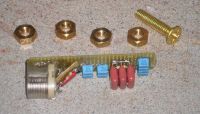
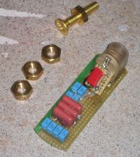
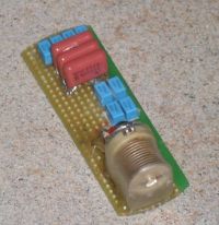
lower division values are 6.64nF and 37.59 kOhms.
compensator is 51ohms, in parallel with 254-324pF variable capacitor.
Patrick, Mon Oct 31 2011, 12:05AM
New work from 10/30/2011:


lower division values are 6.64nF and 37.59 kOhms.
compensator is 51ohms, in parallel with 254-324pF variable capacitor.
Re: High voltage probe for O-scope, 2 of 2, ( FABRICATION ).
Patrick, Sun Nov 06 2011, 03:19AM
New work as of Nov 5... Almost done!
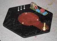
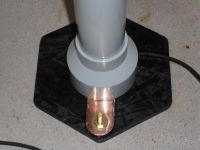
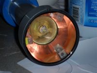
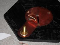
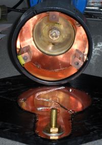
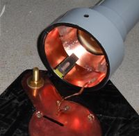
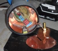
I used non fluxed copper de-soldering briad for the ground/shield connection.
Patrick, Sun Nov 06 2011, 03:19AM
New work as of Nov 5... Almost done!


I used non fluxed copper de-soldering briad for the ground/shield connection.
Re: High voltage probe for O-scope, 2 of 2, ( FABRICATION ).
Patrick, Sun Nov 06 2011, 07:09PM
Finished!!!!!!!!!!!!!!!!!!!!!!!!!! ( I Hope. )
EDIT: it looks GOOD, real good, so far at low freq (60 Hz) at 6000 Vac RMS... now i really need that callibrator!
EDIT 2: it can resolve on sine waves of 60uS which is about 17kHz, which was way better then the purely resistive dividers ive built in the past...
EDIT 3: it sees all sorts of stuff with an iggy and a 18 V battery... This THING ACTUALLY WORKS !
EDIT 4: I can verify a point proud mary and i pondered, if you disable the X10 button its the normal 10,000:1 ratio, but enable the 10X button and it becomes a 1000:1 ratio! How cool is that!
Testing will begin in a few hours, i have math homework i gotta do now though.
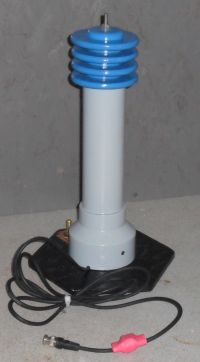
She still needs her permanent tats which ill print out and laminate soon.

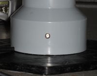
Single trimmer for compensation, weeping yet Tektronix p601* users?
Patrick, Sun Nov 06 2011, 07:09PM
Finished!!!!!!!!!!!!!!!!!!!!!!!!!! ( I Hope. )
EDIT: it looks GOOD, real good, so far at low freq (60 Hz) at 6000 Vac RMS... now i really need that callibrator!
EDIT 2: it can resolve on sine waves of 60uS which is about 17kHz, which was way better then the purely resistive dividers ive built in the past...
EDIT 3: it sees all sorts of stuff with an iggy and a 18 V battery... This THING ACTUALLY WORKS !
EDIT 4: I can verify a point proud mary and i pondered, if you disable the X10 button its the normal 10,000:1 ratio, but enable the 10X button and it becomes a 1000:1 ratio! How cool is that!
Testing will begin in a few hours, i have math homework i gotta do now though.

She still needs her permanent tats which ill print out and laminate soon.


Single trimmer for compensation, weeping yet Tektronix p601* users?
Re: High voltage probe for O-scope, 2 of 2, ( FABRICATION ).
Patrick, Wed Nov 09 2011, 03:02AM
I gonna try to get this transformer working for some super HV, maybe 30 plus kV....
As, Proud Mary sugggested ive been able to find A 65 volt sub coil, its not intended to be used as a primary but it has the same AWG wire as the orignal primary, and has sbout 0.5 ohms or less.
I dont see any oscillograms of Flybacks here on the forum so ill gather some.
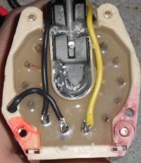
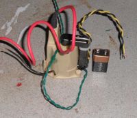
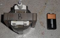
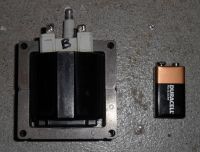
Twisted green wires are for a thermistor at the hot spot. Yellow and black twisted pair is the primary. single black and large red is for secondary HV out. 9v for scale.
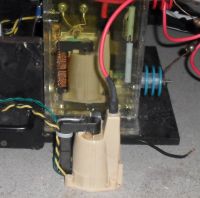
OLd variant in oil tank, new mod in fore ground.
EDIT: i have to be careful im getting 2.2 inch HOT sparks between two sharp points. Ill be using a series output resistor to prevent a short lived flyback. I have to admit the internaL primary does seem much better.
Patrick, Wed Nov 09 2011, 03:02AM
I gonna try to get this transformer working for some super HV, maybe 30 plus kV....
As, Proud Mary sugggested ive been able to find A 65 volt sub coil, its not intended to be used as a primary but it has the same AWG wire as the orignal primary, and has sbout 0.5 ohms or less.
I dont see any oscillograms of Flybacks here on the forum so ill gather some.


Twisted green wires are for a thermistor at the hot spot. Yellow and black twisted pair is the primary. single black and large red is for secondary HV out. 9v for scale.

OLd variant in oil tank, new mod in fore ground.
EDIT: i have to be careful im getting 2.2 inch HOT sparks between two sharp points. Ill be using a series output resistor to prevent a short lived flyback. I have to admit the internaL primary does seem much better.
Re: High voltage probe for O-scope, 2 of 2, ( FABRICATION ).
Patrick, Mon Dec 19 2011, 04:02AM
OOPS! i made a blunder, the lower division resistor should be 75k ohms, not the quoted 37.5k ohms, DUH. i forgot that the both the C and R parrallel dividers are supposed to divide by 5,000:1 then then the compensation and anti reflection components in the cord divide by 2:1, therefore 5,000:1 in series with 2:1 yields a 10,000:1 total ratio.

in the above schematic R4 is shown as 37.5k ohms, but should be 75k ohms. My error.
Patrick, Mon Dec 19 2011, 04:02AM
OOPS! i made a blunder, the lower division resistor should be 75k ohms, not the quoted 37.5k ohms, DUH. i forgot that the both the C and R parrallel dividers are supposed to divide by 5,000:1 then then the compensation and anti reflection components in the cord divide by 2:1, therefore 5,000:1 in series with 2:1 yields a 10,000:1 total ratio.

in the above schematic R4 is shown as 37.5k ohms, but should be 75k ohms. My error.
Re: High voltage probe for O-scope, 2 of 2, ( FABRICATION ).
Sulaiman, Mon Dec 19 2011, 01:58PM
Patrick,
sorry to comment so late in the project but based on the circuit diagram that you posted
the dc attenuation and ac attenuation (or lf and hf if you like) are different,
and the bottom arrangement of 75k (or 37k5) feeding a terminated 50 Ohm transmission line is 'unusual'.
Re: High voltage probe for O-scope, 2 of 2, ( FABRICATION ).
Patrick, Mon Dec 19 2011, 10:23PM
Patrick, Mon Dec 19 2011, 10:23PM
Sulaiman wrote ...
Patrick,
sorry to comment so late in the project but based on the circuit diagram that you posted
the dc attenuation and ac attenuation (or lf and hf if you like) are different,
and the bottom arrangement of 75k (or 37k5) feeding a terminated 50 Ohm transmission line is 'unusual'.
please elaborate, keeping in mind i did use this source,Patrick,
sorry to comment so late in the project but based on the circuit diagram that you posted
the dc attenuation and ac attenuation (or lf and hf if you like) are different,
and the bottom arrangement of 75k (or 37k5) feeding a terminated 50 Ohm transmission line is 'unusual'.
Re: High voltage probe for O-scope, 2 of 2, ( FABRICATION ).
Turkey9, Tue Dec 20 2011, 05:58AM
For the values that he has, it will be pretty linear up to 10 Mhz according to an LTspice sim I just ran.
But that brings up the question, why do you want the capacitors in there? With a purely resistive divider, there are no frequency concerns. Is it because there will be capacitance there anyway since it is a real life circuit and you want to be able to control it?
Re: High voltage probe for O-scope, 2 of 2, ( FABRICATION ).
Patrick, Tue Dec 20 2011, 06:30AM
First, yes i cant have a purely resistive divider due to the stray capacitences i need to control.
Second, what happens after 10Mhz?\
Third, Id like to artificailly limit the bandwidth to some value less than about 100Mhz.
EDIT: Im thinking of adding a 18 V bi directional TVS, across the coax shield and center pin. This would protect the Oscope from inductive kick, since i use many Autotransformers which can be dangerously noisy. At 18V id be able to avoid clipping up to 180 kV (for a 42kV capable probe) I dont think the devices stray capacitence would matter if inserted between the 300pF, and two 6.4 nF caps.
EDIT: i think ive found the resonant freq of my best HEI iggy coil.... I think its 3-5kHz...

(EDIT: from tough to trough is 178uS)
I only tapped a 9V battery to the HEI iggy and captured this waveform...
5.08 Kv peak, 800 volt ring below ground. 254 uS for the main pulse (i think) 1/0.000254 = 3937 Hz, i think thats close to its resonant freq.
EDIT: i wonder if those first six concave downs could be integrated to find the arrea under the main 5kV pulse?
If there are 6 cylinders, at 3000 rpm thats (3000/60) x 6 = 300 sparks per second.
1/300 sec divided by 254uS would yield about 13. So the dead space would be 12 time periods, for each 254uS spark.
Patrick, Tue Dec 20 2011, 06:30AM
Turkey9 wrote ...
For the values that he has, it will be pretty linear up to 10 Mhz according to an LTspice sim I just ran.
But that brings up the question, why do you want the capacitors in there? With a purely resistive divider, there are no frequency concerns. Is it because there will be capacitance there anyway since it is a real life circuit and you want to be able to control it?
First, yes i cant have a purely resistive divider due to the stray capacitences i need to control.
Second, what happens after 10Mhz?\
Third, Id like to artificailly limit the bandwidth to some value less than about 100Mhz.
EDIT: Im thinking of adding a 18 V bi directional TVS, across the coax shield and center pin. This would protect the Oscope from inductive kick, since i use many Autotransformers which can be dangerously noisy. At 18V id be able to avoid clipping up to 180 kV (for a 42kV capable probe) I dont think the devices stray capacitence would matter if inserted between the 300pF, and two 6.4 nF caps.
EDIT: i think ive found the resonant freq of my best HEI iggy coil.... I think its 3-5kHz...

(EDIT: from tough to trough is 178uS)
I only tapped a 9V battery to the HEI iggy and captured this waveform...
5.08 Kv peak, 800 volt ring below ground. 254 uS for the main pulse (i think) 1/0.000254 = 3937 Hz, i think thats close to its resonant freq.
EDIT: i wonder if those first six concave downs could be integrated to find the arrea under the main 5kV pulse?


If there are 6 cylinders, at 3000 rpm thats (3000/60) x 6 = 300 sparks per second.
1/300 sec divided by 254uS would yield about 13. So the dead space would be 12 time periods, for each 254uS spark.
Re: High voltage probe for O-scope, 2 of 2, ( FABRICATION ).
Turkey9, Tue Dec 20 2011, 09:09PM
Wow that's really cool! It will be great to actually get wave forms from all the transformers we to get HV. If that wave form came from tapping the 9V to the primary, what are all those little pulses before the big one? Noise from the mechanical contact? I'd expect them not to be as uniform as they are.
I only ran the sweep in the sim to 10 Mhz, but at that point the attenuation had dropped a couple dB. Up at that frequency the ratio will decrease so keep that in mind when making accurate measurements.
Re: High voltage probe for O-scope, 2 of 2, ( FABRICATION ).
Patrick, Tue Dec 20 2011, 09:38PM
Patrick, Tue Dec 20 2011, 09:38PM
Turkey9 wrote ...
Wow that's really cool! It will be great to actually get wave forms from all the transformers we to get HV. If that wave form came from tapping the 9V to the primary, what are all those little pulses before the big one? Noise from the mechanical contact? I'd expect them not to be as uniform as they are.
yes its so cool! and fun too! but i think the small sines are the primary oscillating unitil the magnetic air gap collapses, then causing the main pulse to appear at the secondary. Wow that's really cool! It will be great to actually get wave forms from all the transformers we to get HV. If that wave form came from tapping the 9V to the primary, what are all those little pulses before the big one? Noise from the mechanical contact? I'd expect them not to be as uniform as they are.
Turkey9 wrote ...
I only ran the sweep in the sim to 10 Mhz, but at that point the attenuation had dropped a couple dB. Up at that frequency the ratio will decrease so keep that in mind when making accurate measurements.
can you post a pic? CHIT! 10MHz ii was hoping for at least 50MHz! can you extend the graph alittle to 20-30MHz?I only ran the sweep in the sim to 10 Mhz, but at that point the attenuation had dropped a couple dB. Up at that frequency the ratio will decrease so keep that in mind when making accurate measurements.
Re: High voltage probe for O-scope, 2 of 2, ( FABRICATION ).
Turkey9, Wed Dec 21 2011, 03:24AM
Sure. Here are two, one to 50Mhz and one to 100Mhz. This is where you really see the non-linearity. The solid line is the attenuation, the dotted line is the phase shift.


Turkey9, Wed Dec 21 2011, 03:24AM
Sure. Here are two, one to 50Mhz and one to 100Mhz. This is where you really see the non-linearity. The solid line is the attenuation, the dotted line is the phase shift.
Re: High voltage probe for O-scope, 2 of 2, ( FABRICATION ).
Patrick, Wed Dec 21 2011, 04:01AM
what was the circuit you programmed into pspice? can you post it?
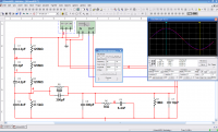
Ive also simulated this one and verified it performance with MULTIsim 10...

Dan McCauley's device from EVR.
Patrick, Wed Dec 21 2011, 04:01AM
Turkey9 wrote ...
Sure. Here are two, one to 50Mhz and one to 100Mhz. This is where you really see the non-linearity. The solid line is the attenuation, the dotted line is the phase shift.


I must have made the caps to big....? Thats not at all what i expected. though ive had bogus and wrong simulations befoer...Sure. Here are two, one to 50Mhz and one to 100Mhz. This is where you really see the non-linearity. The solid line is the attenuation, the dotted line is the phase shift.
what was the circuit you programmed into pspice? can you post it?
Ive also simulated this one and verified it performance with MULTIsim 10...

Dan McCauley's device from EVR.
Re: High voltage probe for O-scope, 2 of 2, ( FABRICATION ).
Turkey9, Wed Dec 21 2011, 05:01AM
Well looks like I made a mistake in the simulation. I forgot that in Spice M is the same as m so the plots I posted before were with 125 miliohm resistors! Oops!
I redid the sim with the right values and got a very different plot. There is still something interesting, however. The plot below is to 10kHz and stays completely flat all the way past 10GHz. The low frequency is interesting though.

Sorry for the error!
Turkey9, Wed Dec 21 2011, 05:01AM
Well looks like I made a mistake in the simulation. I forgot that in Spice M is the same as m so the plots I posted before were with 125 miliohm resistors! Oops!
I redid the sim with the right values and got a very different plot. There is still something interesting, however. The plot below is to 10kHz and stays completely flat all the way past 10GHz. The low frequency is interesting though.

Sorry for the error!
Re: High voltage probe for O-scope, 2 of 2, ( FABRICATION ).
Patrick, Wed Dec 21 2011, 07:29AM
Now that i can live with!
Wooo, i was worried. That looks more familiar, but why 5 decibels lost between zero and 2kHZ? i predicted less...
EDIT:
let me remindmy self of the decibel/log systems.
ok from 74.5dB to 79.5dB means a 100,000 times difference so... how does this relate to my division ratio? hmmmm, must sleep...ZZZZzzzZZZzZzZzzzzZzZ
Re: High voltage probe for O-scope, 2 of 2, ( FABRICATION ).
Patrick, Thu Dec 22 2011, 08:06AM
it looks like im getting a zero to -3 % error rate. at HF (10-100khz) ii get 9,702 / 10,000 = .97 -1 = 0.03 or 3%
Patrick, Thu Dec 22 2011, 08:06AM
it looks like im getting a zero to -3 % error rate. at HF (10-100khz) ii get 9,702 / 10,000 = .97 -1 = 0.03 or 3%
Re: High voltage probe for O-scope, 2 of 2, ( FABRICATION ).
Steve Conner, Thu Dec 22 2011, 11:58AM
Hey Patrick,
I think it's because of the 6.4nF cap in your anti-reflection device or whatever it is. As far as the capacitive division ratio is concerned, it appears in parallel with C4.
If you didn't take that into account, there's twice as much capacitance in the lower arm of the thing as you thought. The capacitive division ratio works out about 6dB lower than the resistive one, and the time constant of the error is a few hundred Hz (6.4nF and 75k) That matches the error shown in the LTSpice sim.
The simulations won't show the true behaviour at really high frequencies, because the simple model of a 125M resistor with a 4pF cap across it starts to break down: the big HV resistors actually have distributed capacitance to their surroundings. That's what all the other trimmers in the Tektronix HV probe are for.
That said, I'm sure your probe will be a valuable tool once you get the little bugs ironed out.
Re: High voltage probe for O-scope, 2 of 2, ( FABRICATION ).
Patrick, Thu Dec 22 2011, 07:58PM
Patrick, Thu Dec 22 2011, 07:58PM
Dr. Watt The Fork wrote ...
Hey Patrick,
I think it's because of the 6.4nF cap in your anti-reflection device or whatever it is. As far as the capacitive division ratio is concerned, it appears in parallel with C4.
If you didn't take that into account, there's twice as much capacitance in the lower arm of the thing as you thought. The capacitive division ratio works out about 6dB lower than the resistive one, and the time constant of the error is a few hundred Hz (6.4nF and 75k) That matches the error shown in the LTSpice sim.
The simulations won't show the true behaviour at really high frequencies, because the simple model of a 125M resistor with a 4pF cap across it starts to break down: the big HV resistors actually have distributed capacitance to their surroundings. That's what all the other trimmers in the Tektronix HV probe are for.
That said, I'm sure your probe will be a valuable tool once you get the little bugs ironed out.
I wasnt expecting to use this device past 100MHz or so....Hey Patrick,
I think it's because of the 6.4nF cap in your anti-reflection device or whatever it is. As far as the capacitive division ratio is concerned, it appears in parallel with C4.
If you didn't take that into account, there's twice as much capacitance in the lower arm of the thing as you thought. The capacitive division ratio works out about 6dB lower than the resistive one, and the time constant of the error is a few hundred Hz (6.4nF and 75k) That matches the error shown in the LTSpice sim.
The simulations won't show the true behaviour at really high frequencies, because the simple model of a 125M resistor with a 4pF cap across it starts to break down: the big HV resistors actually have distributed capacitance to their surroundings. That's what all the other trimmers in the Tektronix HV probe are for.
That said, I'm sure your probe will be a valuable tool once you get the little bugs ironed out.
Re: High voltage probe for O-scope, 2 of 2, ( FABRICATION ).
Patrick, Tue Dec 27 2011, 09:18PM
im trying to figure out what to do for a roll off circuit, and i still dont know why the dc to 2kHz isnt flat.
im really gettign frustrated.
Ive found an inductance calculator too...
Patrick, Tue Dec 27 2011, 09:18PM
im trying to figure out what to do for a roll off circuit, and i still dont know why the dc to 2kHz isnt flat.
im really gettign frustrated.
Ive found an inductance calculator too...

Re: High voltage probe for O-scope, 2 of 2, ( FABRICATION ).
Patrick, Thu Dec 29 2011, 12:24AM
new data, progress made, i realize how to get the graph of both phase and magnitude substantially flat.
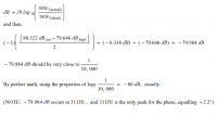
The math!

Bode plots, on the left is magnitude, on the right is phase.
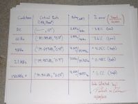
Categorized data from the above bode plots.
Critical points from the above graphs and data, from DC to 130MHz and above to + infinity....
(note that at 311Hz the phase peaks at 2.2 degrees.)
a double blunder on my part, the 37.5k resistor is right, the 75k resistor is wrong! oops!
Given the recurrence of 311Hz, i believe the resistive and capacitive components converge at this freq,
311Hz is where teh phase shift peaks at 2.2 degrees.
311Hz is where the division ratio is closest to 10,000:1 (or -80dB).
The resistive elements below 311Hz show 375Mohms of impedance.
the capaciteve elements show significantly higher impedance (than 375Mohms) below 311Hz
therefore, i conclude that between DC -311Hz the capcitors contribute little or no current. Thus the resistors are making the real measurement.
However, nearing 311Hz the capacitors begin to contribute more current and begin to equal the resistive current. it is at this point that the cap dividers (1:5,000 div(sub C)) current begins to equal the resistive dividers (1:10,000 div(sub R)) current.
Above 311Hz the capcitive impedance falls far below 375Mohms, so whatever current is provided via the 10,000:1 resistive divider is overwelmed and pulled towards the capacitive divider's voltage due to the C's lower impedance, and higher current contribution. Therefore, i believe that significantly above the 311Hz mark, the capacitors are making the real measurement.
This makes a happy finding (perhaps). It might be possible to build a capacitive voltage divider that functions from about 500Hz to 1GHz with no or fewer supporting components in the probe circuit, and still have good response, at the expense of DC and low freq measurement.
Patrick, Thu Dec 29 2011, 12:24AM
new data, progress made, i realize how to get the graph of both phase and magnitude substantially flat.

The math!

Bode plots, on the left is magnitude, on the right is phase.

Categorized data from the above bode plots.

Critical points from the above graphs and data, from DC to 130MHz and above to + infinity....
(note that at 311Hz the phase peaks at 2.2 degrees.)

a double blunder on my part, the 37.5k resistor is right, the 75k resistor is wrong! oops!
Given the recurrence of 311Hz, i believe the resistive and capacitive components converge at this freq,
311Hz is where teh phase shift peaks at 2.2 degrees.
311Hz is where the division ratio is closest to 10,000:1 (or -80dB).
The resistive elements below 311Hz show 375Mohms of impedance.
the capaciteve elements show significantly higher impedance (than 375Mohms) below 311Hz
therefore, i conclude that between DC -311Hz the capcitors contribute little or no current. Thus the resistors are making the real measurement.
However, nearing 311Hz the capacitors begin to contribute more current and begin to equal the resistive current. it is at this point that the cap dividers (1:5,000 div(sub C)) current begins to equal the resistive dividers (1:10,000 div(sub R)) current.
Above 311Hz the capcitive impedance falls far below 375Mohms, so whatever current is provided via the 10,000:1 resistive divider is overwelmed and pulled towards the capacitive divider's voltage due to the C's lower impedance, and higher current contribution. Therefore, i believe that significantly above the 311Hz mark, the capacitors are making the real measurement.
This makes a happy finding (perhaps). It might be possible to build a capacitive voltage divider that functions from about 500Hz to 1GHz with no or fewer supporting components in the probe circuit, and still have good response, at the expense of DC and low freq measurement.
Re: High voltage probe for O-scope, 2 of 2, ( FABRICATION ).
HV Enthusiast, Fri Jul 27 2012, 12:35AM
Hi Patrick,
Yeah, i just got your PM and saw you were trying to simulate my divider on PSPICE.
Like Steve said, you really can't get a good simulation on PSPICE with just basic components as shown in the schematic.
The actual simulation that was used to design this actually is very complex and utilized both Maxwell EM and SPICE. All components were modeled with all their parasitics and even the potting material (dielectric constant) and geometry of the potting / unit itself was utilized to create a good simulation model to get flat response across the band.
Re: High voltage probe for O-scope, 2 of 2, ( FABRICATION ).
Patrick, Tue Jul 31 2012, 09:25PM
what other parasitic values did you find, nH and fF ? can i approximate those too in simulation?
i also used a physical model fr caluculation of filed distribution, that FEMM pic in the first page here. iwas following the pdf from marco denicolais work.
Patrick, Tue Jul 31 2012, 09:25PM
what other parasitic values did you find, nH and fF ? can i approximate those too in simulation?
i also used a physical model fr caluculation of filed distribution, that FEMM pic in the first page here. iwas following the pdf from marco denicolais work.
Print this page