Simple Interrupter Design with Design Sheets / Artwork / Templates
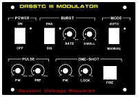
HV Enthusiast, Tue Jun 27 2006, 11:43AMHere is a simple generic interrupter (modulator) design which can be used for both SSTCs, DRSSTCs, and VTTCs. Based on standard 555 timer astable and monostable configurations, it features:
Adjustable Pulsewidth
Adjustable PRF (BPS)
Burst Mode (Adjustable Rate and Dwell times)
Single-shot mode with adjustable PW and lock-out debounce
The single-shot mode allows you to specify pulse duration (up to 5ms) in my example, and also includes a lock-out circuit to prevent retriggering which has its own adjustable delay.
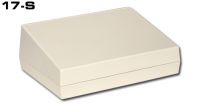
The complete design will be added to my website in a few days, but here is the preliminary schematic, excel design sheet to customize your interrupter, a front panel design, and the box the front panel design was designed for. The box, made by Serpac (Model 17S), is available in black and white in EMI style enclosure. I'll also be adding artwork to my website for download which is designed to go with the $51.00 ExpressPCB order (3 boards)
Enjoy!

Schematic (Preliminary)
]1151408599_15_FT0_advanced_modulator01.pdf[/ file]
Design Sheet - EXCEL
]1151408599_15_FT0_interrupter.zip[/file]

Re: Simple Interrupter Design with Design Sheets / Artwork / Templates
ragnar, Tue Jun 27 2006, 11:50AM
Aw, cute!
How high does can the PW/PRF circuit theoretically go, disregarding the 300hz setting?
ragnar, Tue Jun 27 2006, 11:50AM
Aw, cute!
How high does can the PW/PRF circuit theoretically go, disregarding the 300hz setting?
Re: Simple Interrupter Design with Design Sheets / Artwork / Templates
HV Enthusiast, Tue Jun 27 2006, 01:13PM
will depend on whatever the limitation of the 555 chip is and what the system is capable of.
HV Enthusiast, Tue Jun 27 2006, 01:13PM
will depend on whatever the limitation of the 555 chip is and what the system is capable of.
Re: Simple Interrupter Design with Design Sheets / Artwork / Templates
coaster_chris, Tue Jun 27 2006, 07:18PM
Nice work Dan! It looks very good!
Might be something for me if I will get my SSTC working some day...
Chris
coaster_chris, Tue Jun 27 2006, 07:18PM
Nice work Dan! It looks very good!
Might be something for me if I will get my SSTC working some day...

Chris
Re: Simple Interrupter Design with Design Sheets / Artwork / Templates
Reaching, Wed Jun 28 2006, 10:27AM
mhh, nice work dan, from what i understand you can adjust the PW and PRF independend from each other, so for example 100ys stays the same regardless on what you set the Pw? exactly what i want, dont need the other modes though.
Reaching, Wed Jun 28 2006, 10:27AM
mhh, nice work dan, from what i understand you can adjust the PW and PRF independend from each other, so for example 100ys stays the same regardless on what you set the Pw? exactly what i want, dont need the other modes though.

Re: Simple Interrupter Design with Design Sheets / Artwork / Templates
HV Enthusiast, Wed Jun 28 2006, 11:38AM
Yes. The PRF 555 is the classic 555 astable single RC oscillator producing pulses at some rate. These pulses are your overall PRF. The negative edge of these pulses is then used to trigger the PW 555 and produce a pulse which is output to the DRSSTC. Both are independent of each other. Its not my design, but lifted right out of one of the app notes on the 555 timer. The burst adjust is merely another gating and works an as OR basicaly to the output of the PW 555 chip. This burst mode addition was borrowed from Steve Ward's intteruptor circuit he has on his website.
I originally had planned on using a PIC based interruptor design with lots of features and the first prototype worked very well, but it just took too long to make different adjustments and got to be a pain in the arse. So, i went completely analog using discrete components so adjustments could be made very quickly on the fly.
I'll be uploading artwork, etc... to my website soon.
HV Enthusiast, Wed Jun 28 2006, 11:38AM
Reaching wrote ...
mhh, nice work dan, from what i understand you can adjust the PW and PRF independend from each other, so for example 100ys stays the same regardless on what you set the Pw? exactly what i want, dont need the other modes though.
mhh, nice work dan, from what i understand you can adjust the PW and PRF independend from each other, so for example 100ys stays the same regardless on what you set the Pw? exactly what i want, dont need the other modes though.

Yes. The PRF 555 is the classic 555 astable single RC oscillator producing pulses at some rate. These pulses are your overall PRF. The negative edge of these pulses is then used to trigger the PW 555 and produce a pulse which is output to the DRSSTC. Both are independent of each other. Its not my design, but lifted right out of one of the app notes on the 555 timer. The burst adjust is merely another gating and works an as OR basicaly to the output of the PW 555 chip. This burst mode addition was borrowed from Steve Ward's intteruptor circuit he has on his website.
I originally had planned on using a PIC based interruptor design with lots of features and the first prototype worked very well, but it just took too long to make different adjustments and got to be a pain in the arse. So, i went completely analog using discrete components so adjustments could be made very quickly on the fly.
I'll be uploading artwork, etc... to my website soon.
Re: Simple Interrupter Design with Design Sheets / Artwork / Templates
Reaching, Wed Jun 28 2006, 08:02PM
nice circuit, i tried it out today and it works really fine, you can adjust the on and off times nearly independend from each other, that is great.. but Dan whats the use of this diode in the circuit (1n4002)?there is no difference with or without the diode in place
Re: Simple Interrupter Design with Design Sheets / Artwork / Templates
HV Enthusiast, Thu Jun 29 2006, 12:39AM
Recall, that there is no DC connection between U2 and U3 timer circuits. Each circuit is AC coupled only through capacitor, C7. When U2 output is in steady state (non-switching), the trigger input to U3 is pulled up to +9V through R9. Regardless if the output of U2 is low or high, the trigger input to U3 is pulled high. The only thing that the trigger wants to see is a negative going pulse (to less than 1/3 Vcc). When the output of U2 goes from high to low, this negative pulse will go through capacitor, C7 and pull the trigger input low, thereby triggering U3. However, when the output of U2 goes from low to high, there is a tendency for the trigger input voltage (because it is now DC decoupled) to go above +9V. This is where the diode, CR3 comes in. It protects the trigger input from excessive voltages as when the trigger input exceeds about 9.7 volts, it will conduct through the diode to the rail, and thereby reduce spiking.
HV Enthusiast, Thu Jun 29 2006, 12:39AM
Reaching wrote ...
nice circuit, i tried it out today and it works really fine, you can adjust the on and off times nearly independend from each other, that is great.. but Dan whats the use of this diode in the circuit (1n4002)?there is no difference with or without the diode in place
nice circuit, i tried it out today and it works really fine, you can adjust the on and off times nearly independend from each other, that is great.. but Dan whats the use of this diode in the circuit (1n4002)?there is no difference with or without the diode in place
Recall, that there is no DC connection between U2 and U3 timer circuits. Each circuit is AC coupled only through capacitor, C7. When U2 output is in steady state (non-switching), the trigger input to U3 is pulled up to +9V through R9. Regardless if the output of U2 is low or high, the trigger input to U3 is pulled high. The only thing that the trigger wants to see is a negative going pulse (to less than 1/3 Vcc). When the output of U2 goes from high to low, this negative pulse will go through capacitor, C7 and pull the trigger input low, thereby triggering U3. However, when the output of U2 goes from low to high, there is a tendency for the trigger input voltage (because it is now DC decoupled) to go above +9V. This is where the diode, CR3 comes in. It protects the trigger input from excessive voltages as when the trigger input exceeds about 9.7 volts, it will conduct through the diode to the rail, and thereby reduce spiking.
Re: Simple Interrupter Design with Design Sheets / Artwork / Templates
Steve Conner, Thu Jun 29 2006, 09:14AM
I'll take this opportunity to pimp my DRSSTC interrupter too.

It allows the pulse width to be adjusted from 10 to 300us and the rep rate from 0 to 200Hz. The adjustments don't interact with each other, and turning the rep rate control to zero puts it into a single shot mode with lockout. It doesn't have burst mode like EVR's design, but it does have a linear adjustment law, so you can easily make scales for the knobs, or use 10-turn pots with counter dials. I'm working on adding the long pulse feature that Ward used to such effect.
It also features the scopeboy.com exclusive "Big Red Lighty Up Skull And Crossbones Fire Button".
Steve Conner, Thu Jun 29 2006, 09:14AM
I'll take this opportunity to pimp my DRSSTC interrupter too.


It allows the pulse width to be adjusted from 10 to 300us and the rep rate from 0 to 200Hz. The adjustments don't interact with each other, and turning the rep rate control to zero puts it into a single shot mode with lockout. It doesn't have burst mode like EVR's design, but it does have a linear adjustment law, so you can easily make scales for the knobs, or use 10-turn pots with counter dials. I'm working on adding the long pulse feature that Ward used to such effect.

It also features the scopeboy.com exclusive "Big Red Lighty Up Skull And Crossbones Fire Button".

Re: Simple Interrupter Design with Design Sheets / Artwork / Templates
HV Enthusiast, Thu Jun 29 2006, 10:42AM
Your circuit should be able to do the long pulsewidth feature as is in one-shot mode.
Anyways, here is my final schematic. I ordered the wrong switches (DPST instead of DPDT), so i had to make a few modifications to work with my front panel set-up. Works great!
]1151577766_15_FT12187_advanced_modulator01.pdf[/ file]
HV Enthusiast, Thu Jun 29 2006, 10:42AM
wrote ...
I'm working on adding the long pulse feature that Ward used to such effect.
I'm working on adding the long pulse feature that Ward used to such effect.
Your circuit should be able to do the long pulsewidth feature as is in one-shot mode.
Anyways, here is my final schematic. I ordered the wrong switches (DPST instead of DPDT), so i had to make a few modifications to work with my front panel set-up. Works great!
]1151577766_15_FT12187_advanced_modulator01.pdf[/ file]
Print this page