DRSS.. Good zero-current switching?
Marko, Sun Jun 25 2006, 12:17PMBefore plugging my DRSSTC (
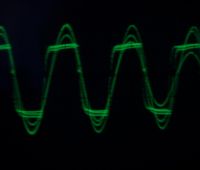
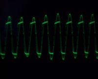
 into mains again II wanted to check reality of primary feedback, and lacking experience I'm unable to determine it these waveforms are rally ZCS.
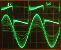
Sine is primary current, just about 20A with overloaded supply (it gave some 20-30 volts at this point)
Current doesn't change phase at higher-voltage bursts.
Under it there is gate drive vaveform.
I mached them on axis and they seem to cross zero just about the right time.


(sorry for crappy pics, I hope axis is at least somewhat visible

I had huge trouble with triggering on crappy old scope, and some readings look pretty garbled.
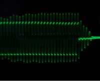
Thing that vorried me more, is ringing left on gate drive after it is 'shut off', and this seems to reflect on primary current also ringing for a while.
This could be very hard for IGBT's, especially ringing in possible linear region. (but it also could be a simple noise on scope probe wich is connected via aligator clip)
I need to take a better look at this.
Sorry for noob questions..
Re: DRSS.. Good zero-current switching?
HV Enthusiast, Sun Jun 25 2006, 01:47PM
Kind of hard to say with those waveforms as they are hard to see. But, the first waveform looks slightly off and not "perfect" ZCS. There is a phase lag on the current waveform. Is it really an issue? Probably not, especially for a smaller coil that doesn't dissipate much power, but i would think you would probably be able to do better than that. It may be measurement error or triggering error as well.
Re: DRSS.. Good zero-current switching?
Steve Ward, Sun Jun 25 2006, 06:13PM
So, you've pumped all this energy into the tank circuit, so where did it go? Well, not all of it goes to the load, and some of it has to return back to your filter cap supply. These last few decaying cycles of primary current are simply when your bridge becomes a bridge rectifier (the internal diodes) and the energy is rectified back to the DC bus. This is why its necessary to have good reverse diodes! I heard someone saying that they dont use IGBTs with diodes, and have not added diodes, and somehow their IGBTs survive?! Either the person that said it was mistaken, or his IGBTs are going through some serious reverse-bias stresses.
Steve Ward, Sun Jun 25 2006, 06:13PM
Thing that vorried me more, is ringing left on gate drive after it is 'shut off', and this seems to reflect on primary current also ringing for a while.
So, you've pumped all this energy into the tank circuit, so where did it go? Well, not all of it goes to the load, and some of it has to return back to your filter cap supply. These last few decaying cycles of primary current are simply when your bridge becomes a bridge rectifier (the internal diodes) and the energy is rectified back to the DC bus. This is why its necessary to have good reverse diodes! I heard someone saying that they dont use IGBTs with diodes, and have not added diodes, and somehow their IGBTs survive?! Either the person that said it was mistaken, or his IGBTs are going through some serious reverse-bias stresses.
Re: DRSS.. Good zero-current switching?
Marko, Sun Jun 25 2006, 06:30PM
Pretty elite explanation, Steve, and makes perfect sense.
Thanks...
Marko, Sun Jun 25 2006, 06:30PM
So, you've pumped all this energy into the tank circuit, so where did it go? Well, not all of it goes to the load, and some of it has to return back to your filter cap supply. These last few decaying cycles of primary current are simply when your bridge becomes a bridge rectifier (the internal diodes) and the energy is rectified back to the DC bus. This is why its necessary to have good reverse diodes! I heard someone saying that they dont use IGBTs with diodes, and have not added diodes, and somehow their IGBTs survive?! Either the person that said it was mistaken, or his IGBTs are going through some serious reverse-bias stresses.
Pretty elite explanation, Steve, and makes perfect sense.
Thanks...
Print this page
